Table of Contents
Advertisement
Quick Links
Advertisement
Table of Contents

Subscribe to Our Youtube Channel
Related Manuals for Gossen MetraWatt METRAport 3A


Summary of Contents for Gossen MetraWatt METRAport 3A
- Page 1 Operating Instructions METRAport 3-349-303-15 Analog Multimeter 3/6.09...
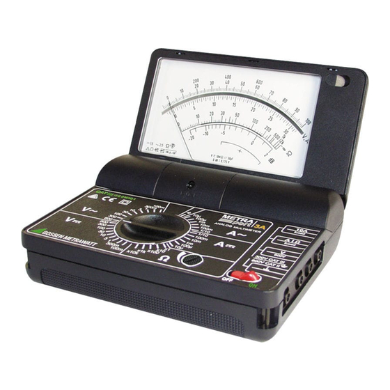
- Page 2 1 Scale 2 Cover of battery compartment 3 Connection socket „10 A“ for the highest current range 4 Connection socket for the measuring range A| 5 Connection socket for the measuring range V (high potential) 6 Connection socket for all measuring ranges 7 Eye for fastening of the carrying strap 8 OFF|ON: on/off switch (off when the instrument is closed) 9 Potentiometer full scale deflection setting for resistance measurement...
-
Page 3: Table Of Contents
Contents Safety Features and Precautions ............4 Application ....................6 Description .....................6 Operation ....................7 Controls ....................7 Starting the Instrument ................9 Voltage Measurement ................10 4.3.1 DC and AC Voltages up to 600 V (Direct Connection) ........10 4.3.2 DC Voltages up to 30 kV with High Voltage Probe HV 30 ......11 Current Measurement ................12 4.4.1 DC and AC Currents up to 1 A (Direct Connection) ........13 4.4.2 DC and AC Currents up to 10 A (Direct Connection) ........14... -
Page 4: Safety Features And Precautions
Safety Features and Precautions You have selected an instrument which provides you with a high level of safety. This instrument fulfills the requirements of the applicable European and national EC guidelines. We confirm this with the CE marking. The relevant declaration of conformity can be obtained from GMC-I Messtechnik GmbH. - Page 5 • No measurements may be performed with this instrument in elec- trical circuits with corona discharge (high voltage). • Special care is required when measurements are made in HF elec- trical circuits. Dangerous pulsating voltages may be present. • Measurements under moist ambient conditions are not permitted. •...
-
Page 6: Application
Repairs, Parts Replacement and Balancing When the instrument is opened, voltage conducting parts may be exposed. The instrument must be disconnected from the measuring circuit before repair, replacement of parts or balancing. If repair or bal- ancing of a live, open instrument is required, this may only be carried out by trained personnel who are familiar with the dangers involved. -
Page 7: Operation
Several well-tuned protection means protect the instrument against damage through improper handling and overload within the specified limit values for overload: • Overdimensioned precision resistors • Melting fuse in conjunction with protective power diodes • Overvoltage arrester The instrument operates independent of the mains on a commercially available 9 V flat cell battery. - Page 8 changing the current measuring ranges. When making current and voltage measurements, take care that the range switch is first set to the highest measuring range. Then work down to lower measuring ranges until optimum display is obtained. Attention! When the measuring voltage, e.g. 250 V , is applied, do not switch to the resistance measuring ranges.
-
Page 9: Starting The Instrument
Special measuring leads the connection plugs of which are protected against accidental contact (lead set KS 17) as well as all leads with banana plugs (4 mm diameter) can be plugged onto the sockets. Melting fuses for measuring circuit (see also chapter 5). Potentiometer ... -
Page 10: Voltage Measurement
Checking the battery voltage If the pointer is within the zone marked with the battery symbol „ “ after the instrument has been turned on then the battery voltage is suf- ficient that is, it is assured that the error limits according to the data given in chapter 5 „Technical Data“... -
Page 11: Dc Voltages Up To 30 Kv With High Voltage Probe Hv 30
4.3.2 DC Voltages up to 30 kV with High Voltage Probe HV 30 Voltages of greater than 600 V can be measured with a high-voltage measuring probe, for example the HV3 (up to 3 kV) of the HV30 (up to 30 kV, DC only) from GMC-I Messtechnik GmbH HV30 black... -
Page 12: Current Measurement
4.4 Current Measurement Attention! The multimeter should be connected into the line having the lowest voltage to earth. For safety reasons, the voltage to earth must not exceed 600 V CAT II or 300 V CAT III! The measuring circuit must be set up mechanically solid and protected against accidental opening. -
Page 13: Dc And Ac Currents Up To 1 A (Direct Connection)
4.4.1 DC and AC Currents up to 1 A (Direct Connection) ➭ Disconnect the power supply to the measuring circuit and/or power con- sumer (R ), and dis- charge all capacitors, if avail- able. ➭ Set the range switch to position 1/10 A 1/10 A~. -
Page 14: Dc And Ac Currents Up To 10 A (Direct Connection)
4.4.2 DC and AC Currents up to 10 A (Direct Connection) ➭ Disconnect the power supply to the measuring circuit and/or power con- sumer (R ), and dis- charge all capacitors, if avail- able. ➭ Set the range switch to position 1/10 A 1/10 A~. -
Page 15: Ac Currents With (Clip-On) Current Transformers
4.4.4 AC Currents with (Clip-on) Current Transformers I(A) Attention! Prior to closing the primary circuit, verify that the secondary circult is closed. If current transformers are operated in open state on the secondary side, e.g. due to defective or not con- nected leads, due to a blown fuse because of prior overload, or due to a wrong position of the range switch (not on the cur- rent range), dangerously high voltages can appear at the con-... -
Page 16: Dc And Ac Currents With (Clip-On) Current Sensors
➭ Set the range switch to position A~. ➭ Select the measuring range of the multimeter as a function of the measuring range and the transformation ratio of the clip-on trans- former. ➭ Connect the measurement cables as shown. ➭ Set switch to position „ON“. ➭... -
Page 17: Measurement Of Composite Voltages And Composite Currents
4.5 Measurement of Composite Voltages and Composite Currents The multimeter allows for separate measurements of DC and AC com- ponents of composite voltages and composite currents. Attention! The sum of the DC and AC components of the measured vari- able shall not exceed the permissible limit values for overload according to chapter 5, and/or the response values of the protective means! 4.5.1 Composite Voltages... -
Page 18: Resistance Measurement
4.6 Resistance Measurement For resistance measurement, the resistance R to be measured is switched in parallel to the internal resistance. That is why with open = ) the scale input terminals (R value (full scale deflection) is indi- cated. The polarity of the voltage to be measured corresponds to the markings on the connection sock- ets „A|“... - Page 19 ➭ Set the range switch to position x 1 ... k x 10. ➭ Set switch to position „ON“. ➭ With adjustment potentiometer, adjust to full scale deflection ➭ Connect the measurement cables as shown. ➭ Read the resistance value on the ...
-
Page 20: Test Of Diodes And Transistors
4.7 Test of Diodes and Transistors The resistance measuring ranges k x 1 and k x 10 are also suited for coarse functional tests of diodes and transistors. A short circuit or an interruption of a diode and/or a diode path between base, collector and emitter of a transistor can be found in a simply way with a "resis- tance measurement". - Page 21 Diode Transistor Measure- ment on socket on socket on socket Forward A| A| A| direction Reverse A| A| A| direction B= Basis C= Collector E= Emitter Valuation of a diode and/or the diode path of a transistor A diode and/or a transistor functions when the indication on the V, A scale during a measurement in forward direction is smaller than the indication during a measurement in reverse direction.
-
Page 22: Technical Data
Technical Data Level Overload Input Voltage Protection Resistance R Const. Measuring Span up to –40 ... –1 8 dB 600 V 100 mV –20 dB –30 ... – 8 dB 600 V 300 mV –10 dB –20 ... + 2 dB 600 V 0 dB –10 ... - Page 23 Open- Short- Mid-Scale Overload Circuit Circuit Resistance Value Read-out Range Protec- Voltage Current Range tion up to 1 ... 45,6 x 2 k 100 mV 2,2 mA 600 V x 10 10 ... 20 k 456,0 ...
- Page 24 Influencing variables and rated operating ranges +5 ... +23 ... +35 C Temperature +5 ... +35 C Limit temperatures for accuracy 0 ... +40 C for operation –25 ... +65 C (without battery) for storage Position additional influence effect max. 1% of scale length when the scale is inclined to the horizontal 120 ...
- Page 25 Fuse Range up to 1 A and FF 1.6A/600V, 6 mm x 32 mm protects the 10 µA ... 1 A and x1 ... k x10 ranges in conjunction with the power diodes Switching capacity: 50 kA with 600 V~ (one half wave on ohmic load) overload limit of the melting fuse in conjunction with the power diodes: max.
-
Page 26: Maintenance
Maintenance Attention! Disconnect the instrument completely from the measuring cir- cuit before opening the battery compartment to replace the battery! 6.1 Battery The state of the battery should be checked from time to time. A dis- charged or deteriorating battery shall not be left in the battery com- partment. - Page 27 Melting Fuse for the mA Range (up to 1 A) The built-in FF 1.6A/600V AC melting fuse for the measuring circuit up to 1 A/can be checked for continuity on the resistance measuring ranges, preferrably on the x 1 range. With the measuring sockets „A|“...
-
Page 28: Housing
6.3 Housing No special maintenance is required for the housing. Keep outside sur- faces clean. Use a slightly dampened cloth for cleaning. Avoid the use of cleansers, abrasives or solvents. Repair and Replacement Parts Service Calibration Center and Rental Instrument Service When you need service, please contact: GMC-I Service GmbH Service-Center...
Need help?
Do you have a question about the METRAport 3A and is the answer not in the manual?
Questions and answers