Table of Contents
Advertisement
Quick Links
Advertisement
Table of Contents

Subscribe to Our Youtube Channel
Related Manuals for Robe ROBIN UV Strobe


Summary of Contents for Robe ROBIN UV Strobe
- Page 1 Version 1.3...
-
Page 2: Table Of Contents
Robin UV Strobe Table of contents 1. Safety instructions ......................3 2. Fixture exterior view ...................... 5 3. Installation........................6 3.1 Connection to the mains .................... 6 3.2 Installing the gel frame and barndoors ............... 7 3.3 Rigging the fixture and floor installation of the fixture ..........8 3.4 DMX-512 connection .................... -
Page 3: Safety Instructions
Please consider that damages caused by manual modifications to the device are not subject to warranty. The Robin UV Strobe was designed mainly for indoor use and it is intended for professional applications only. It is not for household use. - Page 4 as this can result in fire or electric shock. Do not allow anything to rest on the power cord. Do not locate this fixture where the cord may be damaged by persons walking on it. Make sure that the power cord is never crimped or damaged by sharp edges. Check the fixture and the power cord from time to time.
-
Page 5: Fixture Exterior View
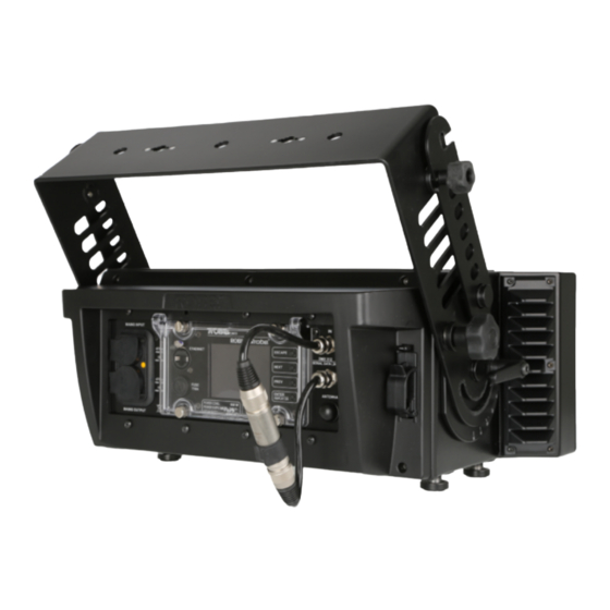
2. Fixture exterior view 1 - Glass cover and lens array 2 - U-holder 3 - Tilt lock 4 - Antenna 5 - DMX IN 6 - DMX OUT 7 - Control buttons 8 - QVGA touch screen 9 - Fuse holder 10 - RJ 45 Input 11 - Power In 12 - Safety screw... -
Page 6: Installation
3.1 Connection to the mains For protection from electric shock, the fixture must be earthed! The Robin UV Strobe is equipped with auto-switching power supply that automatically adjusts to any 50-60Hz AC power source from 100-240 Volts. Connect the fixture to the mains by means of the enclosed power cord If you need to install other plug on the power cord, note that the cores in the power cord are coloured according to the following table. -
Page 7: Installing The Gel Frame And Barndoors
3.2 Installing the gel frame and barndoors Disconnect the fixture from mains before the accessory installation. Never operate the fixture with barndoors closed. 1. Put the frame adaptor (1) on the fixture and secure it with four screws (2). 2. Insert the gel frame (4) into slots (3) of the frame adaptor (1). -
Page 8: Rigging The Fixture And Floor Installation Of The Fixture
3.3 Rigging the fixture and floor installation of the fixture A structure intended for installation of the fixture (s) must safely hold weight of the fixture(s) placed on it. The structure has to be certificated to the purpose. The fixture (fixtures) must be installed in accordance with national and local electrical and construction codes and regulation.. - Page 9 Single fixture installation via the omega holder 1. Bolt the clamp (1) to the omega holder (2) with M12 bolt and lock nut through the hole in the holder. 2. Fasten the omega holder to the U-holder (4) of the fixture by inserting both quick-lock fasteners (3) into holes in the U-holder and tighten fully clockwise.
- Page 10 To install multiple fixtures in a top-to-bottom method 1. Rig the stacker to the truss (4) by means of two omega holders (2) on the U-holder (5) and two clamps (1) and secure it with two safety wires (15). Use only safety wires with snap hook with screw lock gate. The snap hooks have to go throw holes in the stacker.
- Page 11 Always keep correct orientation of fixtures towards the stacker. Warning for outdoor operation! To ensure declared IP rating, the fixture must be in the following positions only (towards ground). Allowed tilt must not be higher than +/-15° from a horizontal axis of the fixture. The display covering transparent cover must be closed and its four screws fully tightened.
- Page 12 Multiply fixtures installation via floor stand Maximum 6 fixtures can be connected in the top-to-bottom method Always use a floor stand for multiply fixture installation in the top-to-bottom method on the floor. To install multiple fixtures in the top-to-bottom method on the floor stand 1.
-
Page 13: Dmx-512 Connection
3.4 DMX-512 connection The fixture is equipped with 5-pin XLR sockets for DMX input and output.The sockets are wired in parallel. Only use a shielded twisted-pair cable designed for RS-485 and 5-pin XLR-plugs and connectors in order to connect the controller with the fixture or one fixture with another. DMX - output DMX-input 1 - Shield... -
Page 14: Ethernet Connection
3.5 Ethernet connection The fixtures on a data link are connected to the Ethernet with ArtNet communication protocol.The control soft- ware running on your PC (or light console) has to support Art-Net protocol. Art-Net communication protocol is a 10 Base T Ethernet protocol based on the TCP/IP.Its purpose is to allow transfer of large amounts of DMX 512 data over a wide area using standard network technology. - Page 15 Ethernet / DMX operation Option “ Artnet" (gMaI or gMA2 or sACN) has to be selected from “Ethernet Mode” menu at first fixture. Option “Ethernet To DMX” has to be selected from the “Ethernet Mode” menu at the first fixture (connected to the Ethernet) in the fixture chain, next fixtures have standard DMX setting.
-
Page 16: Control Menu Map
4. Control menu map Default settings=Bold print Level 1 Level 2 Level 3 Level 4 Level 5 Level 6 Addressing Settings DMX Address 001-255 DMX Presets Mode 1 Mode 4 Ethernet Settings Ethernet Mode Disable ArtNet gMAI gMA2 sACN Ethernet To DMX IP Address/NetMask Default IP Address Custom IP Address... - Page 17 Level 1 Level 2 Level 3 Level 4 Level 5 Level 6 DMX Presets Mode 1 Mode 4 View Selected Preset DMX Input Wired Input Wireless Input Wireless In/XLR Out Microphone Sen- 1-10-20 sitivity Douse Settings Off, On Dimmer Curve Linear Square Law Init Effect Positions...
-
Page 18: Dmx Chart
DMX protocol 5. DMX chart Robin Strobe - DMX protocol Version: 1.2 Mode 1 – Zone effects mode , Mode 2 –Zone mode , Mode 3 –Three channel mode , Mode 4 – Four channel mode Mode/channel Type of Function value control Intensity (8bit)-all zones... - Page 19 DMX protocol Mode/channel Type of Function value control 13-14 Effect 6 step 15-16 Effect 7 step 17-18 Effect 8 step 19-20 Effect 9 step 21-22 Effect 10 step 23-24 Effect 11 step 25-26 Effect 12 step 27-28 Effect 13 step 29-30 Effect 14 step...
-
Page 20: Strobe And Special Effects Running
6. Strobe and Special effects running 6.1 Strobe Mode 3 and 4 Mode 1 and 2 6.2 Special effects Rumping Rump Up Rump Down... - Page 21 Rump Up/Down Lightning Mode 1, 2, 4 Spikes For Duration and Rate timing serves the same values as for strobe...
-
Page 22: Control Menu
7. Control menu The Robin UV Strobe Light is equipped with the QVGA Robe touch screen with battery backup which allows to set the fixture´s behaviour according to your needs, obtain information on its operation, test its various parts and lastly program it, if it has to be used in a stand-alone mode. -
Page 23: Tab " Address
The menu page displays icons for each function that you can perform from the touch screen. After switching the fixture on, the touch screen shows the screen with the ROBE logo: Touch any part of the screen or press the [ENTER/Display On] button to display the initial screen with the cur-... -
Page 24: Tab "Information
Resetable Hours - The item shows the number of the operation hours that the Robin UV Strobe has been powered on since the counter was last reset. In order to reset this counter to 0, touch the text box next to the item "Resetable Hours:"... -
Page 25: Tab "Personality
7.3 Tab "Personality" User mode - The Robin UV Strobe allows you to recall up to 3 user settings. After switching the fixture on for the first time, the User A settings is active. Now all changes made in the “Personality” menu , ”Addressing”... -
Page 26: Tab "Manual Control
Play Program 2 - The option starts user program No. 2. Play Program 3 - The option starts user program No. 3. Edit Program - Use the menu to create or to edit desired program. The Robin UV Strobe offers 3 free programs, each up to 88 steps. -
Page 27: Tab "Service
3. Run the Software Uploader program. Select desired COM and then click on the Connect button. (Select COM if the serial port is used or Robe Universal Interface if the USB port is used). If the connection is OK, click on the “Start Uploading button“ to start uploading. It will take several minutes to perform software update. -
Page 28: Rdm
ROBE_WIRELESS_UNLINK 9. Wireless DMX operation The wireless DMX version of the Robin UV Strobe is equipped with the Lumen Radio CRMX module and antenna for receiving DMX signal. CRMX module operates on the 2.4 GHz band. The item " Wireless " from the menu "DMX Input" allows you to activate receiving of wireless DMX (Person- ality-->... -
Page 29: Error And Information Messages
Note: If the fixture is placed outdoor during wireless DMX operation , both its XLR connectors has to be interconnected each other (male-female) to meet their IP rating (IP 65). 10. Error and information messages Occurred errors during fixture operation are signalled by the yellow warning icon at the bottom line of the screen: Touch the warning icon or press the [ESCAPE] button to display error messages. -
Page 30: Technical Specifications
11. Technical Specifications Electrical Power supply:......electronic auto-ranging Input voltage range:....100-240V, 50/60Hz Fuse:........T8 A Max. power consumption:..660 W @230V (power factor=0,98, I=2.93A) Optic Light source: 120 high power LEDs (40 white, 80 UV /385nm/) 12 LED zones with individual control of each Typical Lumen Maintenance: 70% @ 16,000 hours Zone effectsl Zone effects in both directions with variable speed... - Page 31 Minimum distance Min. distance from inflammable surfaces: 0.5 m Total heat dissipation 2050 BTU/h (calculated) Weight (net): 14.3 kg Dimensions (mm) Protection factor IP 22 Accessories Omega holder (P/N.99010420)........1 pc Cap for XLR connector (P/N 19020175)....1 pc Optional accessories (P/N 10 980 261) Floor stands for Robin Strobe (P/N 10 980 262) Bandoor for Robin Strobe (P/N 10 980 263) Frame Adaptor for Robin Strobe (P/N 10 980 264) Gel Frame for Robin Strobe...
-
Page 32: Maintenance And Cleaning
12. Maintenance and cleaning DANGER ! Disconnect from the mains and allow to cool completely before starting any cleaning or maintenance work The front transparent cover will require monthly cleaning as smoke fluid tends to build up residues, reducing the light output very quickly. For cleaning use a wet clout and a vacuum-cleaner or air-jet. Do not use solvents or any other aggressive cleaning fluid. -
Page 33: Extract From A Test Report Of Brno University Of Technology - Light Laboratory
**Calculated values for illuminance of detector E=500lx. These values are decisive for determining of hazard group Full report from the Light Laboratory on request. Copyright © 2016-2017 Robe Lighting - All rights reserved Specifications are subject to change without notice. -
Page 34: Appendix
14. Appendix 14.1 Strobe and Special effects timing... - Page 35 Strobe duration Mode 3 and 4 Mode 1 and 2 50Hz 60Hz 50 and 60 Hz [ms] [ms] [ms] 20,00 16,67 13,31 20,00 16,67 16,64 20,00 16,67 19,97 20,00 16,67 23,30 20,00 16,67 26,62 20,00 16,67 29,95 20,00 16,67 33,28 20,00 16,67 36,61...
- Page 36 Strobe duration Mode 3 and 4 Mode 1 and 2 50Hz 60Hz 50 and 60 Hz [ms] [ms] [ms] 140,00 116,67 193,02 140,00 116,67 196,35 140,00 116,67 199,68 140,00 116,67 203,01 140,00 116,67 206,34 140,00 116,67 209,66 140,00 116,67 212,99 140,00 116,67 216,32...
- Page 37 Strobe duration Mode 3 and 4 Mode 1 and 2 50Hz 60Hz 50 and 60 Hz [ms] [ms] [ms] 260,00 216,67 372,74 260,00 216,67 376,06 280,00 233,33 379,39 280,00 233,33 382,72 280,00 233,33 386,05 280,00 233,33 389,38 280,00 233,33 392,70 280,00 233,33 396,03...
- Page 38 Strobe duration Mode 3 and 4 Mode 1 and 2 50Hz 60Hz 50 and 60 Hz [ms] [ms] [ms] 400,00 333,33 552,45 400,00 333,33 555,78 400,00 333,33 559,10 400,00 333,33 562,43 420,00 350,00 565,76 420,00 350,00 569,09 420,00 350,00 572,42 420,00 350,00 575,74...
- Page 39 Strobe duration Mode 3 and 4 Mode 1 and 2 50Hz 60Hz 50 and 60 Hz [ms] [ms] [ms] 540,00 450,00 732,16 540,00 450,00 735,49 540,00 450,00 738,82 540,00 450,00 742,14 540,00 450,00 745,47 540,00 450,00 748,80 560,00 466,67 752,13 560,00 466,67 755,46...
- Page 40 Strobe Rate Mode 3 and 4 Mode 1 and 2 50Hz 60Hz 50Hz 60Hz [Hz] [Hz] [Hz] [Hz] 0,289 0,347 0,289 0,347 0,289 0,347 0,347 0,417 0,431 0,517 0,431 0,517 0,431 0,517 0,495 0,594 0,575 0,690 0,575 0,690 0,575 0,690 0,641 0,769 0,714...
- Page 41 Strobe Rate Mode 3 and 4 Mode 1 and 2 50Hz 60Hz 50Hz 60Hz [Hz] [Hz] [Hz] [Hz] 3,571 4,286 3,846 4,615 3,571 4,286 3,846 4,615 3,846 4,615 3,846 4,615 3,846 4,615 4,167 5,000 3,846 4,615 4,167 5,000 3,846 4,615 4,167 5,000 4,167...
- Page 42 Strobe Rate Mode 3 and 4 Mode 1 and 2 50Hz 60Hz 50Hz 60Hz [Hz] [Hz] [Hz] [Hz] 7,143 8,571 8,333 10,000 7,143 8,571 8,333 10,000 7,143 8,571 8,333 10,000 7,143 8,571 8,333 10,000 7,143 8,571 8,333 10,000 7,143 8,571 8,333 10,000 7,143...
- Page 43 Strobe Rate Mode 3 and 4 Mode 1 and 2 50Hz 60Hz 50Hz 60Hz [Hz] [Hz] [Hz] [Hz] 10,000 12,000 12,500 15,000 10,000 12,000 12,500 15,000 10,000 12,000 12,500 15,000 10,000 12,000 12,500 15,000 10,000 12,000 12,500 15,000 10,000 12,000 12,500 15,000 10,000...
- Page 44 Strobe Rate Mode 3 and 4 Mode 1 and 2 50Hz 60Hz 50Hz 60Hz [Hz] [Hz] [Hz] [Hz] 12,500 15,000 16,667 20,000 12,500 15,000 16,667 20,000 12,500 15,000 16,667 20,000 12,500 15,000 16,667 20,000 12,500 15,000 16,667 20,000 12,500 15,000 16,667 20,000 12,500...
- Page 45 Strobe Rate Mode 3 and 4 Mode 1 and 2 50Hz 60Hz 50Hz 60Hz [ms] [ms] [ms] [ms] 3460,00 2883,34 3460,00 2883,34 3460,00 2883,34 2880,00 2400,00 2320,00 1933,34 2320,00 1933,34 2320,00 1933,34 2020,00 1683,34 1740,00 1450,00 1740,00 1450,00 1740,00 1450,00 1560,00 1300,00 1400,00...
- Page 46 Strobe Rate Mode 3 and 4 Mode 1 and 2 50Hz 60Hz 50Hz 60Hz [ms] [ms] [ms] [ms] 280,00 233,33 260,00 216,67 280,00 233,33 260,00 216,67 260,00 216,67 260,00 216,67 260,00 216,67 240,00 200,00 260,00 216,67 240,00 200,00 260,00 216,67 240,00 200,00 240,00...
- Page 47 Strobe Rate Mode 3 and 4 Mode 1 and 2 50Hz 60Hz 50Hz 60Hz [ms] [ms] [ms] [ms] 140,00 116,67 120,00 100,00 140,00 116,67 120,00 100,00 140,00 116,67 120,00 100,00 140,00 116,67 120,00 100,00 140,00 116,67 120,00 100,00 140,00 116,67 120,00 100,00 140,00...
- Page 48 Strobe Rate Mode 3 and 4 Mode 1 and 2 50Hz 60Hz 50Hz 60Hz [ms] [ms] [ms] [ms] 100,00 83,33 80,00 66,67 100,00 83,33 80,00 66,67 100,00 83,33 80,00 66,67 100,00 83,33 80,00 66,67 100,00 83,33 80,00 66,67 100,00 83,33 80,00 66,67 100,00...
- Page 49 Strobe Rate Mode 3 and 4 Mode 1 and 2 50Hz 60Hz 50Hz 60Hz [ms] [ms] [ms] [ms] 80,00 66,67 60,00 50,00 80,00 66,67 60,00 50,00 80,00 66,67 60,00 50,00 80,00 66,67 60,00 50,00 80,00 66,67 60,00 50,00 80,00 66,67 60,00 50,00 80,00...
- Page 50 Rumping Duration Rumping Rate Mode 4 Mode 1 and 2 Mode 1, 2 and 4 50Hz 60Hz 50Hz 60Hz 50Hz 60Hz [ms] [ms] [ms] [ms] [Hz] [Hz] 2480,00 2066,67 2480,00 2066,67 2600,00 2166,67 2480,00 2066,67 2380,00 1983,34 2600,00 2166,67 2480,00 2066,67 2280,00 1900,00...
- Page 51 Rumping Duration Rumping Rate Mode 4 Mode 1 and 2 Mode 1, 2 and 4 50Hz 60Hz 50Hz 60Hz 50Hz 60Hz [ms] [ms] [ms] [ms] [Hz] [Hz] 600,00 500,00 560,00 466,67 2060,00 1716,67 600,00 500,00 540,00 450,00 2060,00 1716,67 550,00 458,33 540,00 450,00...
- Page 52 Rumping Duration Rumping Rate Mode 4 Mode 1 and 2 Mode 1, 2 and 4 50Hz 60Hz 50Hz 60Hz 50Hz 60Hz [ms] [ms] [ms] [ms] [Hz] [Hz] 320,00 266,67 300,00 250,00 1520,00 1266,67 320,00 266,67 280,00 233,33 1520,00 1266,67 320,00 266,67 280,00 233,33...
- Page 53 Rumping Duration Rumping Rate Mode 4 Mode 1 and 2 Mode 1, 2 and 4 50Hz 60Hz 50Hz 60Hz 50Hz 60Hz [ms] [ms] [ms] [ms] [Hz] [Hz] 200,00 166,67 180,00 150,00 980,00 816,67 200,00 166,67 180,00 150,00 980,00 816,67 200,00 166,67 180,00 150,00...
- Page 54 Rumping Duration Rumping Rate Mode 4 Mode 1 and 2 Mode 1, 2 and 4 50Hz 60Hz 50Hz 60Hz 50Hz 60Hz [ms] [ms] [ms] [ms] [Hz] [Hz] 160,00 133,33 140,00 116,67 440,00 366,67 160,00 133,33 140,00 116,67 440,00 366,67 160,00 133,33 140,00 116,67...
- Page 55 Lightning Rate Mode 1, 2, and 4 50Hz 60Hz [ms] [ms] 2600,00 2166,67 2600,00 2166,67 2580,00 2150,00 2580,00 2150,00 2560,00 2133,34 2560,00 2133,34 2540,00 2116,67 2540,00 2116,67 2520,00 2100,00 2520,00 2100,00 2500,00 2083,34 2500,00 2083,34 2480,00 2066,67 2480,00 2066,67 2460,00 2050,00 2460,00 2050,00...
- Page 56 Lightning Rate Mode 1, 2, and 4 50Hz 60Hz [ms] [ms] 2060,00 1716,67 2060,00 1716,67 2040,00 1700,00 2040,00 1700,00 2020,00 1683,34 2020,00 1683,34 2000,00 1666,67 2000,00 1666,67 1980,00 1650,00 1980,00 1650,00 1960,00 1633,34 1960,00 1633,34 1940,00 1616,67 1940,00 1616,67 1920,00 1600,00 1920,00 1600,00...
- Page 57 Lightning Rate Mode 1, 2, and 4 50Hz 60Hz [ms] [ms] 1520,00 1266,67 1520,00 1266,67 1500,00 1250,00 1500,00 1250,00 1480,00 1233,34 1480,00 1233,34 1460,00 1216,67 1460,00 1216,67 1440,00 1200,00 1440,00 1200,00 1420,00 1183,34 1420,00 1183,34 1400,00 1166,67 1400,00 1166,67 1380,00 1150,00 1380,00 1150,00...
- Page 58 Lightning Rate Mode 1, 2, and 4 50Hz 60Hz [ms] [ms] 980,00 816,67 980,00 816,67 960,00 800,00 960,00 800,00 940,00 783,33 940,00 783,33 920,00 766,67 920,00 766,67 900,00 750,00 900,00 750,00 880,00 733,33 880,00 733,33 860,00 716,67 860,00 716,67 840,00 700,00 840,00 700,00...
- Page 59 Lightning Rate Mode 1, 2, and 4 50Hz 60Hz [ms] [ms] 440,00 366,67 440,00 366,67 420,00 350,00 420,00 350,00 400,00 333,33 400,00 333,33 380,00 316,67 380,00 316,67 360,00 300,00 360,00 300,00 340,00 283,33 340,00 283,33 320,00 266,67 320,00 266,67 300,00 250,00 300,00 250,00...
Need help?
Do you have a question about the ROBIN UV Strobe and is the answer not in the manual?
Questions and answers