Table of Contents
Advertisement
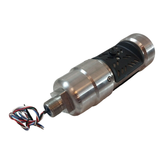
Model IR400
Infrared Point Detector for
Hydrocarbon Gas Applications
The information and technical data disclosed in
this document may be used and disseminated
only for the purposes and to the extent
specifically authorized in writing by General
Monitors.
Instruction Manual
05-11
General Monitors reserves the right to change
published specifications and designs without
prior notice.
Part No.
MANIR400-EU
Revision
D/05-11
Advertisement
Chapters
Table of Contents

Subscribe to Our Youtube Channel
Related Manuals for General Monitors IR400


Summary of Contents for General Monitors IR400
- Page 1 General Monitors. Instruction Manual 05-11 General Monitors reserves the right to change published specifications and designs without prior notice. Part No. MANIR400-EU Revision...
-
Page 3: Table Of Contents
Special Cautions and Warnings ....................5 Installation, Operation, and Maintenance .................. 5 2.0 PRODUCT DESCRIPTION ..................... 6 3.0 INSTALLATION ........................8 Attaching the IR400 to a Junction Box, IR4000S, or IR4000M ..........9 Mounting Instructions ....................... 10 Wiring Connections ........................13 Applying Power ........................15 4.0 OPERATION AND CONFIGURATION ................ - Page 4 Model IR400 9.0 APPENDIX ..........................31 Warranty ........................... 31 Principle of Operation ....................... 32 Specifications ........................... 33 Environmental Specifications ....................36 Communications ........................36 Engineering Documentation ..................... 37 Ordering Information ........................ 38 IR400 HART COMMUNICATION IR400 MODBUS PROGRAMMING...
- Page 5 Figure 6b: IR400 with European Junction Box ..................... 15 Figure 7: Wiring Diagram from IR400 to Control Equipment ................16 Figure 8. IR400 Zero Switch / LED During Zeroing and Calibration ..............21 Figure 9 IR400 Optical Window Locations ......................26 ...
-
Page 6: Quick-Start Guide
Quick-Start Guide Mounting and Orientation The Model IR400 should be mounted horizontally (Figure 1a/Figure 1b) to reduce the likelihood of dirt and dust build-up on the windows. For optimum performance, the splashguards should be located on the top and bottom as shown in Figure 1a/Figure 1b. Apply the supplied thread lubricant/sealant to all conduit entries before use to prevent binding. -
Page 7: Table 1: Wiring Chart
NOTE: Power should remain disconnected until all other wiring connections are made. Power Connections To supply power to the IR400, connect the red lead from the IR400 to the +24 VDC terminal on the power supply. Connect the black lead from the IR400 to the power supply Common. Refer to the manual of the power source being used, for more detailed instructions. -
Page 8: Figure 2: Wiring Diagram From Ir400 To Control Equipment
Model IR400 Figure 2: Wiring Diagram from IR400 to Control Equipment The instrument is now ready to operate. Please further consult this manual for more information on the instrument’s many features. -
Page 9: Introduction
Model IR400 1.0 Introduction 1.1 Protection for Life General Monitors’ mission is to benefit society by providing solutions through industry-leading safety products, services and systems that save lives and protect capital resources from the dangers of hazardous flames, gases and vapors. -
Page 10: Product Description
Applying a test gas to the unit can check the sensitivity of the IR400. It is also relatively maintenance free, requiring only a periodic cleaning of the windows and re-zeroing to ensure dependable performance. - Page 11 Model IR400 Features and Benefits This is a partial list of features and benefits for the Model IR400 infrared point detector: • No routine calibration required • Fail-to-safe operation • 4-20 mA output • Modbus communications link • Optional HART interface •...
-
Page 12: Installation
• NOTE: The Model IR400 is factory calibrated and needs no routine calibration. However, if the IR400 is to be installed at altitudes greater than 1000 ft (300m), it must be re-calibrated on-site (Section 4.1). -
Page 13: Attaching The Ir400 To A Junction Box, Ir4000S, Or Ir4000M
5 mm Allen wrench, and lifting the cover straight up. Strip and trim the wires from the IR400 as needed and thread them into either the right or left wiring conduit of the junction box, IR4000M, or IR4000S. -
Page 14: Mounting Instructions
Fasten the IR400 wires to a wiring connector inside the junction box, IR4000M or IR4000S enclosure. Once the two units are attached, you may replace the cover on the enclosure attached to the IR400 using the four captive screws, or leave it off until additional cabling from the enclosure is completed. -
Page 15: Figure 5B Ir400 Mounting Dimensions With A European Box
Model IR400 Figure 5b IR400 Mounting Dimensions with a European Box... - Page 16 Model IR400 To Mount the IR400 The IR400 must rest horizontally to reduce the possibility of dirt and dust building up on the lens. • The open slots of the gas passage must be straight up and down for the gas to rise up and through the unit.
-
Page 17: Wiring Connections
The maximum distance between the IR400 and the power source is specified in Section 9.3.3. 3.3.1 Power Connections To supply power to the Model IR400 connect the red lead from the IR400 to the +24 VDC terminal on the power supply. Connect the black lead from the IR400 to the power supply Common. - Page 18 3.3.2 4- 20 mA Output A 4 to 20 mA output signal is provided by the Model IR400 and can be sent to a General Monitors’ readout/relay display module or any industrial device that can accept a 4 to 20 mA signal for computer based multi-point monitoring.
-
Page 19: Applying Power
After stabilization, it is recommended that the IR400 be zeroed, per the procedure in Section 4.1 (step 1 only). A gas check should then be performed to ensure that the unit is operating properly. Use the General Monitors gas check kit (P/N 32548-x) to perform this check. -
Page 20: Figure 7: Wiring Diagram From Ir400 To Control Equipment
Model IR400 Figure 7: Wiring Diagram from IR400 to Control Equipment... -
Page 21: Operation And Configuration
The methods used to operate and configure the IR400 will vary depending on whether you are using the IR400 as part of an IR4000M monitoring system, or as a stand-alone unit attached to a junction box and control room devices, or to an IR4000S. Separate instructions are provided in this chapter for each situation. - Page 22 NOTE: You cannot run a gas check test from an FMD or IR4000S attached to an IR400. The FMD and IR4000S have a relay inhibit mode that will turn off the Warn and Alarm relay but the current loop will still transmit the gas concentration level. This could cause alarms on control room equipment.
-
Page 23: Table 3: Ir400 Without Hart Option
General Monitors configures the IR400 with three calibration input options: magnetic switch (default), manual solenoid, and automatic remote gas calibration device (ARGC). To use the manual solenoid or ARGC, purchase a factory configured IR400 or change the calibration input via Modbus or HART. -
Page 24: Ir400 Stand-Alone Operation And Configuration
However, zeroing and calibration can be accomplished using the Zero (magnetic) Switch / LED on the junction box that is directly attached to the IR400. You should ‘zero’ the Model IR400 detectors occasionally to eliminate any background gas fluctuations. Calibration is necessary if gas check readings show the unit is reading inaccurately. -
Page 25: Figure 3: Model Ir400
Review the general guidelines in Section 4.1 on Zeroing, Gas Check Tests, and Calibration. Make sure the windows are clean and there is nothing blocking the optical beam. 4.2.2 Zero Only Calibration The junction box used with the IR400 is fitted with a zero switch which eliminates any background gas fluctuation. Zero Switch Zero the Unit. - Page 26 When the zero calibration is complete, a full span calibration may optionally be performed. 1. Zero the Unit. Apply the General Monitors magnet that was included with the unit to the Zero Switch / LED for approximately three seconds. The LED in the switch will light to show proper placement.
-
Page 27: Hazardwatch Mode
CSA performance requirements. A chamber is filled with a known concentration of gas (static) and the IR400 is then exposed to the gas. This method is defined by the approval agencies and allows us to fill instantaneously the optical path of detector to achieve the stated response times for the IR400. - Page 28 Model IR400 concentration. From the instant of exposure to this gas mixture the instrument shall respond to provide an indication within the time specified as follows: 50% of full scale gas concentration in 10 sec, and 90% of maximum indicated gas concentration in 30 sec. The products offered by GM are not for the purpose of testing T response time, but as a method to allow a user to check that the unit is responding to gas and that final response is within tolerance.
-
Page 29: Maintenance
Model IR400 5.0 Maintenance The Model IR400 is calibrated at the factory and is fail-to-safe; once it is correctly installed and calibrated upon start-up, it requires little maintenance other than periodic cleaning, gas checks, zeroing and recalibration to ensure system integrity. Integrity checks can be performed using General Monitors’... -
Page 30: Cleaning And Lubricating The Ir400 And Ir4000 Units
As an alternative to grease, PTFE (Teflon) tape may be used. 5.4 Storage The Model IR400 Gas Detector and IR4000 Monitor System should be stored in a clean, dry area, and within the temperature and humidity ranges noted for environmental specifications in Section 9.3.3 Electrical Specifications for the IR400, and the separate user manual for the... -
Page 31: Troubleshooting
(if Modbus is being used), and the fault code, shown as F and a number, on the IR4000 display (if connected). If the IR400 is connected to a zero switch, then the LED in the zero switch will blink at a rate of 5 flashes per second to show that the detector needs attention. - Page 32 2mA for 30s Bit 2 Beam Block then 1.25mA then 0mA 2) The IR400 must be returned to the factory 2) Detector or source failure. or authorized service center for repair. 1) Ensure baud rate, data format and Communications Fault 1) Incorrect communications set-up.
-
Page 33: Modbus Interface
(PLCs). The Modbus interface is also used to connect IR400 detectors to the IR4000M multi-point monitor. A separate manual for the IR400 Modbus registers and a programming guide is available from the General Monitors’ website. -
Page 34: Customer Support
Model IR400 8.0 Customer Support Area Phone/Fax/Email UNITED STATES Toll Free: +1-800-446-4872 Corporate Office: Phone: +1-949-581-4464 26776 Simpatica Circle Fax: +1-949-581-1151 Lake Forest, CA 92630 Email: info@generalmonitors.com Phone: +1-281-855-6000 9776 Whithorn Drive Fax: +1-281-855-3290 Houston, TX 77095 Email: gmhou@generalmonitors.com UNITED KINGDOM... -
Page 35: Appendix
9.0 Appendix 9.1 Warranty General Monitors warrants the Model IR400 to be free from defects in workmanship or material under normal use and service within two (2) years from the date of shipment. General Monitors will repair or replace without charge any such defective equipment found to be defective during the warranty period. -
Page 36: Principle Of Operation
The Model IR400 provides a two-wire RS-485 addressable communications link conforming to the Modbus protocol that is used to monitor the IR400’s status and settings in order to simplify installation and maintenance. -
Page 37: Specifications
Model IR400 9.3 Specifications 9.3.1 System Specifications Detector Type: Infrared absorption Detector Life: Greater than 5 years Measuring Range: 0 to 100% LEL Zero Drift: < 2% per year Response Time: T50 ≤ 7 seconds, T60 ≤ 8 seconds (With 100% LEL methane applied) T90 ≤... - Page 38 Model IR400 9.3.2 Mechanical Specifications 8.87 inches (225 mm) Length: Diameter: 2.9 in (74 mm) Weight: 3 lbs (1.35 kg) for aluminum 6 lbs (2.7 kg) for stainless steel Mounting: 3/4" NPT threads Enclosure: Marine Aluminum or Stainless Steel; Explosion proof, IP66, Type 4X 9.3.3 Electrical Specifications...
-
Page 39: Table 6: Analog Current Output
1400 10.9 Table 7: Maximum Distance between IR400 and Power Source Analog Output Signal – The maximum total distance between the IR400 and a device with a 500-Ohm input impedance varies according to the wire size. Stranded Cable (Ω/1000 ft) -
Page 40: Environmental Specifications
Command Data (byte 3). A ”0" in the most significant bit of the Command Word (byte 2), tells the IR400 to return to the current settings. In this case the Command Data (byte 3) will be all “0’s”. -
Page 41: Engineering Documentation
Model IR400 9.6 Engineering Documentation... -
Page 42: Ordering Information
IR4000 single-point monitor connected using IR4000S analog output and CAL signal 9.7.2 Spare Parts and Accessories To order spare parts and/or accessories, please contact the nearest General Monitors representative, or General Monitors directly, and give the following information: 1. Part Number 2. Description 3. - Page 43 Model IR400 9.7.4 Accessories 31305-1 Junction Box with magnetic switch, CSA/FM 31421-3 Junction Box with magnetic switch, ATEX 31305-2 Junction Box without magnetic switch, CSA/FM 31421-4 Junction Box without magnetic switch, ATEX 32554-1 Calibration Cup / Flow Block 32545-1 Splash Guard standard...
- Page 44 Product Disposal Considerations This product may contain hazardous and/or toxic substances. EU Member states shall dispose according to WEEE regulations. For further General Monitors’ product WEEE disposal information please visit: www.generalmonitors.com/customer_support/faq_general.html All other countries or states: please dispose of in accordance with existing federal, state and local...
- Page 45 Model IR400 HART Field Device Specification for Point IR Gas Detector...
- Page 46 Model IR400 HART Table of Contents 1.0 INTRODUCTION ........................1 Scope ..............................1 Purpose ..............................1 Who should use this document? ......................1 References ............................. 1 2.0 DEVICE IDENTIFICATION ..................... 2 3.0 PRODUCT OVERVIEW ......................2 4.0 PRODUCT INTERFACES ...................... 2 Process Interface ............................
- Page 47 Command #193: Do Zero/Calibration ....................24 Command #195: Do Gas Check ......................24 11.0 TABLES ..........................25 IR400 – Device Specific Commands Summary ................... 25 IR400 – Operating Mode Values ......................26 Fault Event Log – Cause Description ....................26 12.0 PERFORMANCE ......................
- Page 48 Table 1: Field Device Identification Data ...................... 2 Table 2: Error Status Information ........................4 Table 3: IR400 – Common Practice Commands ..................5 Table 4: IR400 – Device Specific Commands .................... 25 Table 5: IR400 - Operating Mode Values ....................26 Table 6: Fault Event Log –...
-
Page 49: Introduction
1.0 Introduction Scope The IR400 Combustible Gas detector complies with HART Protocol Revision 6.0. This document specifies all of the device specific features and documents HART Protocol implementation details. The functionality of this Field Device is described sufficiently to allow its proper application in a process and its complete support in HART capable Host Applications. -
Page 50: Device Identification
Table 1: Field Device Identification Data 3.0 Product Overview The IR400 is an Infrared Combustible Gas Detector from General Monitors. The IR400 accurately measures combustible gas and reports the measurement as a percent of the Lower Explosive Limit (%LEL) of the gas. -
Page 51: Local Interfaces, Jumpers, And Switches
Refer to the Installation Manual for connection details. 1.1.3 Local Controls And Displays 1.1.4 There are neither local controls nor displays in the IR400 unit. 1.1.5 Internal Jumpers And Switches 1.1.6 There are no internal jumpers or switches in the IR400 unit. -
Page 52: Status Information
Model IR400 HART 7.0 Status Information The error status, which is returned via Common Practice Command #48, is shown in Table and corresponds to Modbus register 0x02. Device Status Byte Description Class Bits Set IR Close to Low Error Negative Drift... -
Page 53: Universal Commands
Returns error status (same as Modbus register x02), Low Byte Command Returns Power Cycled Flag Command Returns Event Happened Flag Command Value = 0: All OK; Bit 0: Maintenance Required; Bit 1: Critical Fault Command Returns 0 Table 3: IR400 – Common Practice Commands... -
Page 54: Catch Device Variable
This Field Device does not support Catch Device Variable. 10.0 Device Specific Commands The Device Specific commands are used strictly for the unique features of the IR400 and at the discretion of General Monitors. They are described here in section 10.0 and are summarized in Table . -
Page 55: Command #136: Set Alarm Level
Model IR400 HART Command #136: Set Alarm Level This sets the Alarm level. Request Data Bytes Byte Format Description Unsigned-8 Alarm level, % of FS Response Data Bytes Byte Format Description Unsigned-8 Alarm level, % of FS Command-Specific Response Codes... -
Page 56: Command #143: Read Event Logging Counters
Model IR400 HART Command-Specific Response Codes Code Class Description Success No Command-Specific Errors 1 – 2 Undefined Error Passed Parameter Too Large Undefined Error Too Few Data Bytes Received 6 – 15 Undefined Error Access Restricted 17 – 127 Undefined... -
Page 57: Command #144: Clear Event Logging Counters
Model IR400 HART 0 - 1 Unsigned-16 Warning Event Counter 2 - 3 Unsigned-16 Alarm Event Counter 4 - 5 Unsigned-16 Fault Event Counter 6 - 7 Unsigned-16 Maintenance Event Counter 8 - 9 Unsigned-16 Calibrate Event Counter Command-Specific Response Codes... -
Page 58: Command #146: Read Alarm Event Log
Model IR400 HART 0 - 3 Unsigned-32 Event Running Time (in Seconds) 4– 6 Date Event Date: Day, Month, Year – 1900 Unsigned-8 Event Hour Unsigned-8 Event Minute Unsigned-8 Event Second 10-13 Unsigned-8 Reserved = 0 Command-Specific Response Codes Code... -
Page 59: Command #148: Read Maintenance Event Log
Model IR400 HART Event 1 is the one just before that and so forth. Request Data Bytes Byte Format Description None Response Data Bytes Byte Format Description 0 - 3 Unsigned-32 Event Running Time (in Seconds) 4– 6 Date Event Date: Day, Month, Year – 1900... -
Page 60: Command #149: Set Clock
Model IR400 HART Unsigned-8 Event Minute Unsigned-8 Event Second 10-11 Unsigned-16 Reserved = 0 12-13 Unsigned-16 Code Command-Specific Response Codes Code Class Description Success No Command-Specific Errors 1-127 Undefined Command #149: Set Clock This sets the internal real-time clock. Request Data Bytes... -
Page 61: Command #150: Read Clock
Model IR400 HART Command #150: Read Clock This reads the internal real-time clock setting. Request Data Bytes Byte Format Description Response Data Bytes Byte Format Description 0 – 2 Date Date: Day, Month, Year-1900 Unsigned-8 Hours Byte Format Description Unsigned-8... -
Page 62: Command #152: Read Run Time Meter
Model IR400 HART Code Class Description 6 - 127 Undefined Command #152: Read Run Time Meter This reads the internal run time meter. Request Data Bytes Byte Format Description Response Data Bytes Byte Format Description 0 - 3 Unsigned-32 Run Time Meter Value... -
Page 63: Command #155: Get Event Index
Model IR400 HART Command #155: Get Event Index This reads event logged index. Request Data Bytes Byte Format Description None Response Data Bytes Byte Format Description Unsigned - 8 Event index Command-Specific Response Codes Code Class Description Success No Command-Specific Errors... -
Page 64: Command #163: Get Fast Changing Information
Model IR400 HART Code Class Description Success No Command-Specific Errors 1-127 Undefined Command #163: Get Fast Changing Information Request Data Bytes Byte Format Description None... -
Page 65: Command #164: Get Slow Changing Information
Model IR400 HART Response Data Bytes Byte Format Description 0 - 1 Unsigned-16 Mode 2 - 3 Unsigned-16 Sub Mode 4 – 7 Float 8 - 9 Unsigned-16 Priority fault 10 – 11 Bit map Error status Unsigned-8 Reserved = 0... -
Page 66: Command #165: Get Set Up Information
Model IR400 HART Command #165: Get Set Up Information Request Data Bytes Byte Format Description None Response Data Bytes Byte Format Description Unsigned-8 Gas ID Enumerated Measured Units 2- 5 Unsigned-32 Full Scale Unsigned-8 Alarm level, % of FS Unsigned-8... -
Page 67: Command #170: Set Current Range
Model IR400 HART Gas Selection Codes Code to read / write Gas Type Methane Propane N Butane Hexane % by volume Methane Special Order Ethane Pentane Command #170: Set Current Range This sets the current range to be either one of 2 possible selections. -
Page 68: Command #185: Set Gas Id Or Sensor Type
Model IR400 HART Command #185: Set Gas ID or sensor type Request Data Bytes Byte Format Description Unsigned 8 Gas ID or sensor type Response Data Bytes Byte Format Description Unsigned 8 Gas ID or sensor type Command-Specific Response Codes... -
Page 69: Command #187: Set Solenoid State
Model IR400 HART Response Data Bytes Byte Format Description Unsigned 8 0 – zero switch, 1 – manual solenoid, 2 – automatic solenoid Command-Specific Response Codes Code Class Description Success No Command-Specific Errors 1 - 4 Undefined Error Too Few Data Bytes Received... -
Page 70: Command #188: Read Solenoid State
Model IR400 HART Command #188: Read Solenoid State Request Data Bytes Byte Format Description None Response Data Bytes Byte Format Description Unsigned -8 Solenoid State: 0 = disabled, 1 - off, 2 - on Command-Specific Response Codes Code Class Description... -
Page 71: Command #191: Do Zero
Model IR400 HART Command #191: Do Zero This sends the unit to Zero mode. Request Data Bytes Byte Format Description Response Data Bytes Byte Format Description Command-Specific Response Codes Code Class Description Success No Command-Specific Errors 1 - 15 Undefined... -
Page 72: Command #193: Do Zero/Calibration
Model IR400 HART Command #193: Do Zero/Calibration This sends the unit to Zero/Calibration mode. Request Data Bytes Byte Format Description Response Data Bytes Byte Format Description Command-Specific Response Codes Code Class Description Success No Command-Specific Errors 1 - 15 Undefined... -
Page 73: Tables
Model IR400 HART 11.0 Tables IR400 – Device Specific Commands Summary The following Table 4 is a summary of the IR400 Device Specific Commands. Command Byte Number Meaning Number Do Abort Set Alarm Level Set Warn Level Reset Event Happening Flag... -
Page 74: Ir400 - Operating Mode Values
Model IR400 HART IR400 – Operating Mode Values The following Table 5 is a summary of the IR400 Operating Mode Values: Operating Mode Value in Hex Run Mode 0x0001 Calibration Mode 0x0002 Zero Mode 0x0004 Calibration Pending Mode 0x0008 Calibration Apply Gas Mode... -
Page 75: Performance
Busy and Delayed-Response The IR400 does not use delayed-response times. Long Messages The largest data field used by the IR400 is in response to Command 20 & 22 (Read/Write Long Tag): 34 bytes including the two status bytes. Non-Volatile Memory The IR400 uses EEPROM to hold the device’s configuration parameters. -
Page 76: Annex A. Capability Checklist
Model IR400 HART Annex A. Capability Checklist Manufacturer, model, and revision General Monitors, Inc., IR400, Revision 1 Device type Infrared Combustible Gas Detector HART revision Device Description available Number and type of sensors 1 Internal Infrared Number and type of actuators... -
Page 77: Annex B. Default Configuration
Model IR400 HART Annex B. Default Configuration Parameter Default value Lower Range Value 0% LEL Upper Range Value 100% LEL PV Units Percent Lower Explosive Limit Sensor type Infrared Detector Number of wires Damping time constant Fault-indication jumper Write-protect jumper... - Page 78 Model IR400 Infrared Point Detector for Hydrocarbon Gas Applications Modbus programming guide...
- Page 79 Model IR400 MODBUS Table of Contents 10.0MODBUS RTU........................1 10.1 Serial Communications Protocol for IR400 ................1 10.1.1 Baud Rate ........................1 10.1.2 Data Format ........................1 10.1.3 Modbus Read Status Protocol (Query/Response) ............1 10.1.4 Modbus Write Command Protocol (Query/Response) ..........2 10.1.5 Modbus Write Response Message ................
- Page 80 Model IR400 MODBUS 10.4.37 Warning Running Time in Seconds, Low Word (0x00B9) .......... 19 10.4.38 Warning Clock Time: Year, Month (0x00BA) .............. 19 10.4.39 Warning Clock Time: Day, Hour (0x00BB) ..............19 10.4.40 Warning Clock Time: Minute, Second (0x00BC) ............19 10.4.41 Total Warning Event Counter (0x00BF) ..............
-
Page 81: Serial Communications Protocol For Ir400
Modbus ID is 1. These defaults can be restored at any time by connecting the CAL_IO wire (brown) to power supply common and then turn on the power to the IR400. After 10 seconds the CAL_IO wire should be disconnected from the power-supply. -
Page 82: Modbus Write Command Protocol (Query/Response)
IR400 ID (Address) Function Code Read Holding Registers Byte Count No. of Data Bytes Data Hi 00-FF (Hex) IR400 Hi Byte Status Data Data Lo 00-FF (Hex) IR400 Lo Byte Status Data CRC Hi 00-FF (Hex) CRC Hi Byte CRC Lo... -
Page 83: Function Codes Supported
An abnormal communications produces one of four possible events: 4. If the IR400 does not receive the query due to a communications error, then no response is returned from the IR400 and the master device will eventually process a timeout condition for the query. - Page 84 An unrecoverable error occurred while the IR400 was attempting to perform the requested action. Acknowledge The IR400 has accepted the request and is processing it, but a long duration of time will be required to do so. This response is returned to prevent a timeout error from occurring in the master.
-
Page 85: Ir400 Command Register Locations
Model IR400 MODBUS 1.3 IR400 Command Register Locations Register Parameter Function Data Data Range Acces Address Type (Hex) 0-20 mA analog 0000H Analog Output Numeric 0-65535 Dec, Value (scale to range output 0-21.7mA) 0001h Operating Mode Set/View operating Bit Map... - Page 86 Model IR400 MODBUS Rate 19200) 000Ch Modbus Data Set/View Data Format Code 0, 1, 2, 3 Format (8N1, 8E1, 801, 8N2) 000Dh Priority fault Main fault for the unit Bit Map Table 000Eh % of full scale Read gas Numeric -9 –...
- Page 87 Model IR400 MODBUS • 0023h Number of Starting Numeric 0-65535 decimal Starting Register Address Value Register Address errors. errors 0024h Reserved • 0025h Number of CRC HI Numeric 0-65535 decimal errors Value errors HI • 0026h Number of CRC LO...
- Page 88 Model IR400 MODBUS Running Time Low Numeric 0 - 65535 Running Time 00B9h for Warning Event Value log entries Clock Time Hi Hi byte = year, Lo Numeric 1 –99 year, 1– 00Bah byte month: Value 12 month Warning clock time...
- Page 89 Model IR400 MODBUS byte Hour: Fault Value 0 – 23 hour clock time Clock Time Low Hi byte = Minute, Numeric 0 – 59 minutes 00CCh Lo byte second: Value 0 – 59 seconds Fault clock time Fault Code Numeric...
-
Page 90: Ir400 Command Register Details
IR400 scaling which is 0 - 21.7mA. 1.4.2 Operating Mode (Read/Write) This register reports on the current operating mode for the IR400 detector. A Read command returns the present IR400 mode, represented by the enabled bit. The following table shows the mode represented by each bit in the 16-bit register. -
Page 91: Status Error (0X0002)
CAL Mode: Calibration in progress at 50% LEL. Can write 0x0002 only during CAL pending mode, which lasts 30 sec • Zero Mode: Zeroing of the IR400 in progress. Writing 0x0004 to mode register sends the unit to zero mode. •... - Page 92 Model IR400 MODBUS Bit Position Error Heater problem Ref. Lamp Active Lamp Prob. Test forgotten Problem (remove gas) Bit Value 800 hex / 2048 400 hex / 1024 200 hex / 512 100 hex / 256 decimal decimal decimal decimal...
-
Page 93: Gas Selection (0X0003)
A Read returns the model type for the detector, which is 2104 in Decimal format. 1.4.6 Software Rev (0x0005) A read returns the software revision of the IR400 in 2 ASCII characters. The most significant byte is the first character, the least significant byte is the second character. For example, if this register reads 0x2042 then the first digit is 0x20 (a space character) and the second is 0x42 (the character B). -
Page 94: Solenoid On/Off (0X0008)
Address will default to 1. 1.4.11 Baud Rate (0x000B) A read returns the baud rate of the IR400. A write changes the baud rate to the requested baud rate. After the baud rate has been changed to the addressed unit, the Modbus communications will cease because the baud rate has changed;... -
Page 95: Data Format (0X000C)
19600. 1.4.12 Data Format (0x000C) A read returns the data format of the IR400. A write will change the data format to the requested data format. After the data format has been changed, the addressed unit may cease or start producing Comm. errors because the data format has changed; therefore, the master will have to change its data format to the slave’s new data format in order to... -
Page 96: Alarm Level (0X0018)
Model IR400 MODBUS 1.4.15 Alarm Level (0x0018) Sets/reads minimum gas concentration level in % of Full Scale, when alarm event is logged 1.4.16 Warn Level (0x0019) Sets/reads minimum gas concentration level in % of Full Scale, when warn event is logged 1.4.17 HART Configuration (0x001A) -
Page 97: Beam Block Percentage (0X0054)
Model IR400 MODBUS 1.4.26 Beam Block Percentage (0x0054) This register returns a value from 0-100. When the optical path of the IR400 is clear, the reading is 0% blocked. When the register reads near 100 the optical path is blocked and must be cleaned immediately. -
Page 98: Running Time In Seconds Lo Word (0X00B2)
Model IR400 MODBUS 1.4.30 Running Time in seconds lo word (0x00B2) This sets/reads hi word of device running time in seconds. This value must be read/written after running time hi byte (register 0x00B1). Table 15: Real Time Clock Time Format... -
Page 99: Warning Running Time In Seconds, Hi Word (0X00B8)
Model IR400 MODBUS 1.4.36 Warning Running Time in Seconds, Hi Word (0x00B8) This register reads hi word of the running time in seconds when the warning event occurred. This time is in seconds since January 1, 2000. 1.4.37 Warning Running Time in Seconds, Low Word (0x00B9) This register reads the low word of the running time in seconds when the warning event occurred. - Page 100 Model IR400 MODBUS 1.4.48 Fault Running Time in Seconds, Hi Word (0x00C8) This register reads the high word of the running time in seconds when the fault event occurred. This time is in seconds since January 1, 2000. 1.4.49 Fault Running Time in Seconds, Low Word (0x00C9) This register reads the low word of the running time in seconds when the fault event occurred.
- Page 101 Model IR400 MODBUS 1.4.61 Calibration Running Time in Seconds, Hi Word (0x00D8) This register reads the high word of the running time in seconds when the calibration event occurred. This time is in seconds since January 1, 2000. 1.4.62 Calibration Running Time in Seconds, Low Word (0x00D9) This register reads the low word of the running time in seconds when the calibration event occurred.
Need help?
Do you have a question about the IR400 and is the answer not in the manual?
Questions and answers