Table of Contents
Advertisement
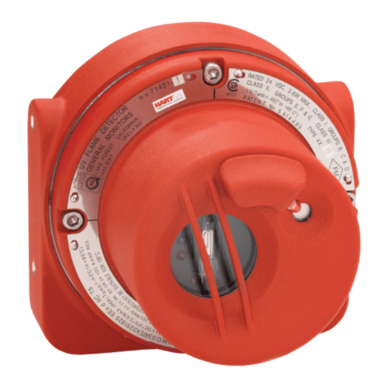
Models FL3100/FL3101
UV/IR and UV only
Flame Detectors
The information and technical data disclosed
in
this
document
disseminated only for the purposes and to the
extent
specifically authorized in writing by
General Monitors.
Instruction Manual
General Monitors reserves the right to change
published specifications and designs without
prior notice.
Part No.
Revision
may
be
used
and
11/01
!"#$%&'(()&'('
MANFL3100/3101
G/11-01
Advertisement
Table of Contents

Subscribe to Our Youtube Channel
Related Manuals for General Monitors FL3100


Summary of Contents for General Monitors FL3100
- Page 1 General Monitors. Instruction Manual 11/01 General Monitors reserves the right to change published specifications and designs without prior notice. !"#$%&'(()&'(' Part No. MANFL3100/3101 Revision G/11-01...
-
Page 2: Warning
Models FL3100/3101 Warranty General Monitors warrants the Models FL3100 and FL3101 to be free from defects in workmanship or material under normal use and service within two years from the date of shipment. General Monitors will repair or replace without charge any such equipment found to be defective during the warranty period. - Page 3 Models FL3100/3101 System Integrity Verification General Monitors mission is to benefit society by providing solutions through industry leading safety products, services and systems that save lives and protect capital resources from the dangers of hazardous flames, gases and vapors. The safety products you have purchased should be handled carefully and installed, calibrated and maintained in accordance with the respective product instruction manual.
- Page 4 Models FL3100/3101 Periodic System Verification The following system verifications should be performed at least annually: Verify wiring, terminal connections and stability of mounting for all integral safety equipment including, but not limited to: • Power supplies • Control modules •...
-
Page 5: Quick Start Guide
Models FL3100/3101 Quick Start Guide 1.0 Quick Start Guide Mount and wire the detector (see pages 2 through 17) Pay special attention to the conduit seal entry (Canadian Electrical Code Handbook Part 1, Section 18-154). Also, lithium based grease is applied to the O-ring seal between the back-plate and housing, as additional protection to avoid water ingression into the housing. - Page 6 Models FL3100/3101 Quick Start Guide 3.75[95.3] 5.00[127.0] 60° 30° 30° 4X M6 X 14 4X M6 WASHER BRACKET ASSEMBLY Figure Q-C 71172 Rear View Bracket Assembly Terminal Block 2 Terminal Block 1 Term # Term # Figure Q-D Field Terminations...
-
Page 7: Apply Power To The Detector
Models FL3100/3101 Quick Start Guide Apply power to the detector. Two light emitting diodes (LED’s) are visible through the UV window (the larger window on UV/IR units). Immediately upon powering up the detector, both LED’s will start blinking alternately for 10 seconds. The unit will then enter the “Ready” mode. During the “Ready"... -
Page 8: Table Of Contents
Models FL3100/3101 Table of Contents Warning ..................i System Integrity Verification................ii Quick Start Guide ...................iv Mount and wire the detector (see pages 2 through 17)....iv Apply power to the detector............vi Test the detector using the TL100 (UV only) or ...... - Page 9 Models FL3100/3101 FL3100, FL3101 Operational Mode Command Register Details.36 8.7.1 Analog ................36 8.7.2 Mode................36 8.7.3 Status/Error ..............36 8.7.4 UV/IR Only ..............36 8.7.5 Model Type..............37 8.7.6 Software Revision ............37 8.7.7 COPM Fault..............37 8.7.8 EEPROM Override ............37 8.7.9 Options ................38 8.7.10 Comm 1 Address............38 8.7.11 Comm 1 Baud Rate............39...
-
Page 10: Table Of Figures
(Class I, Div 1 & 2, Groups B, C & D or Zone 1 and 2).....7 Figure 3-E FL3100 & FL3101 Outline Drawing..........7 Figure 3-F FL3100 & FL3101 Outline Drawing..........8 Figure 3-G FL3100 & Fl3101 Field Terminations ...........8 Figure 3-H Terminal Designations..............9 Figure 3-I Detector Housing and Base ............9 Figure 3-J Terminal Block Operation............10... -
Page 11: Product Description
The Model FL3101, is an Ultraviolet (UV) flame detector (Figure 2-B). It only responds to UV and has been optimized for speed of response. Both units may be used with the General Monitors TA40X Modules, FL802 controller, or with other equipment which accepts the 4 to 20mA output. They may also be interfaced directly with alarm/suppression devices or with switched input modules using integral relays. -
Page 12: Installation
Detector Field of View The Models FL3100 and FL3101 Flame Detectors have a maximum cone of vision of 120° and 140° maximum respectively. This cone has its vertex at the center of the detector (see Figures 2A-1, 2A-2, and 2A-3). -
Page 13: Figure 3A-1 Fl3100 (Uv/Ir) Field Of View
±30° <5' ±45° <5' ±60° <20' <5' +60° SENSITIVITY +45° TABLE CHART 100% 100% VERTICAL 100% +30° 0° ±15° +15° ±30° ±45° <20' (±5°) 0° ±60° <20' <20' VERTICAL -15° -30° -45° -60° Figure 3A-1 FL3100 (UV/IR) Field of View... -
Page 14: Figure 3A-2 Fl3101 (Uv) Field Of View
Models FL3100/3101 0° 15° 15° 30° 30° 45° 45° 60° 60° 50 & 75% 70° 70° 75° 75° 100% (±5°) TABLE CHART HORIZONTAL 100% HORIZONTAL 0° ± 15° ± 30° SENSITIVITY ± 45° ± 60° 100% ± 70° <20' <20' ±... -
Page 15: Mounting And Wiring
Red caps supplied by GM are for dust protection only and must not be left on unit when installed. The Model FL3100/FL3101 Flame Detector should be mounted pointing downward so that dust/moisture will not accumulate on the optical window(s). -
Page 16: Figure 3-B 961-004 Swivel Elbow Drawing (Class I, Div 1 & 2, Groups C & D)
Models FL3100/3101 NOTE - General Monitors does not recommend the use of cable shoes or crimps on any junction box or housing wiring terminals. Poor crimping can cause a bad connection when the unit experiences temperature variations. Good practice is to just terminate unused cable wires following insulation removal. -
Page 17: Figure 3-D 71072 Mounting Bracket Drawing (Class I, Div 1 & 2, Groups B, C & D Or Zone 1 And 2)
4X M6 WASHER BRACKET ASSEMBLY Figure 3-D 71072 Mounting Bracket Drawing (Class I, Div 1 & 2, Groups B, C & D or Zone 1 and 2) 6.2[157.5] 1.50[38.1] .75[19.1] 2X 3/4 NPT ENTRY Figure 3-E FL3100 & FL3101 Outline Drawing... -
Page 18: Figure 3-Ffl3100 & Fl3101 Outline Drawing
Models FL3100/3101 [139.7] 5.0[127.0] 4X M6 X 1 2.94[74.7] 6.2[157.5] 1.63[41.4] .75[19.1] 1.67[42.4] Figure 3-F FL3100 & FL3101 Outline Drawing FIELD TERMINATIONS CHAS GND ALM C ALM 1 +24VDC ALM 2 +24VDC WARN C DATA2- WARN 1 0-20mA DATA2+ WARN 2... -
Page 19: Figure 3-H Terminal Designations
Models FL3100/3101 Power Supply CHASSIS GROUND (ONLY IF REQUIRED) UNIT #2 (IF POWERED IN SERRIES) COM. COM. *ALARM RELAY +24V DC +24V DC *WARN RELAY 0-20 mA ALARM TEST RESET *FAULT RELAY DATA - DATA + CONTROL DEVICE PLC, DCS, ETC... -
Page 20: Figure 3-J Terminal Block Operation
Models FL3100/3101 Figure 3-J Terminal Block Operation Terminal Connections All wire connections are made through the base entries to the terminal block (see Figure 3-J). The terminal block accepts 14 AWG to 22 AWG (2.1 to 0.3mm stranded or solid core wire. Each wire should be stripped to .25” (.64cm). To connect the wire to the terminal block, insert the conductor into the connection space as shown in Figure 3-J and tighten the corresponding screw terminal. - Page 21 TB2, Term 7 = WARN 2 These connections are for the SPDT WARN relay. The WARN output is immediate on the Models FL3100/FL3101. The WARN output can be normally energized or normally de-energized, latching or non-latching, and these options are also set via RS-485 or by a DIP switch. (See Section 4.4 User Selectable Options/Factory Defaults).
- Page 22 Models FL3100/3101 The WARN relay contact ratings are 8A @ 250VAC and 8A @ 24VDC. CAUTION - Inductive loads (bells, buzzers, relays, etc.) on dry relay contacts must be clamped down as shown in Figure 2-J. Unclamped inductive loads can generate voltage spikes in excess of 1000 Volts.
- Page 23 The Flame Detector will remain in this state until the switch is released. NOTE - The latching WARN and/or ALARM will have to be RESET manually. The Alarm Test feature cannot be daisy chained between two or more FL3100/FL3101 Flame Detectors. Analog Output TB1, Term 5 = 0 - 20mA (Analog Output)
- Page 24 470 ohm Alarm resistor and 5.6K EOL. The EOL resistors are onboard the IN042, selectable by DIP-switches. Contact General Monitors or an authorized representative for further details. European Union (EU) Approved Applications: Interconnecting cables must have an overall screen or screen and armor. Cables BS5308 Part 2, Type 2, or equivalent are suitable.
- Page 25 Models FL3100/3101 Cable termination in the non-hazardous area The cable armor must be connected to safety earth in the safe area. The cable screen (drain wire) must be connected to an instrument earth in the safe area. The power supply OV return must be connected to an instrument earth in the safe area.
-
Page 26: Operation
LED will turn off, and the green LED will turn on constant and briefly flash off every 10 seconds. System Test To test the system, use the General Monitors Test Lamp Model TL103 for the FL3100 Flame Detector or the Model TL100 for the FL3101 Detector. (Refer to Section 5.3). -
Page 27: User Selectable Options/Factory Defaults
Models FL3100/3101 User Selectable Options/Factory Defaults All settings on the Models FL3100 and FL3101 are done via a DIP switch on the Power/Relay Board or via MODBUS (overrides switch settings). To set these options, remove the detector head from the Base Assembly and locate the DIP switch (see Figures 4-B1 &... -
Page 28: Figure 4-B1 Dip Switch Location
Models FL3100/3101 PIN 1 Figure 4-B1 Dip Switch Location PIN 1 Figure 4-B2 Dip Switch Location... -
Page 29: Maintenance
General Monitors. The neoprene rubber gasket should also be lubricated with Type P80 lubricant available from General Monitors (P/N 610-010) should it be found to be dry. The removal of dust and film build-up on the windows is necessary to ensure proper sensitivity of the system. -
Page 30: Sensitivity Check
Sensitivity Check To verify that each detector is functioning correctly, a General Monitors Test Lamp and/or the ALARM TEST function should be used. For the Model FL3100 (UV/IR) the General Monitors Model TL103 Test Lamp is recommended. For the Model FL3101 (UV only) the General Monitors Model TL100 Test Lamp is recommended. - Page 31 With the switch in the HI position, the Test Lamp is capable of activating General Monitors’ UV flame detection systems at distances up to 40 feet (12 meters) from the detector. The LO switch will activate the system at distances up to 20 feet (6 meters).
-
Page 32: Storage
It is always important to start a series of TL103 checks with a fully charged unit. Stand within 15 feet (FL3100) or within 35 feet (FL3101) of the unit to be tested and aim the TL103 squarely into the detector face. If the system is operating normally, the detector will go into a WARNING condition after a few flashes of the Test Lamp. -
Page 33: Trouble Shooting
Should the various actions suggested in the table fail to restore normal operation, the unit should be returned to General Monitors for repair. A complete written description of the problem should be included. - Page 34 (UV or associated source light rods. IR window) Constant 8mA signal with no Background IR radiation at Cover IR portion of FL3100 known radiation to detector detector. for ten seconds to determine (FL3100 only). if there is background IR. If...
-
Page 35: Final Assembly
4 PL UV/IR, HOUSING SUBASSY SCR, 8-32 3 PL WASHER, #8 ASSY, BASE LIGHT ROD LENS UV DETECTOR STANDOFF 3 PL CCA DETECTOR BD CCA CONTROL BD COMM BD, SINGLE/DUAL MOBUS CA POWER BD Figure 6-A 71100 FL3100 (UV/IR), Final Assembly... -
Page 36: Figure 6-B 71125 Fl3101 (Uv), Final Assembly
Models FL3100/3101 NAMEPLATE PLUG SCR, M6 SOC HD 4 PL UV HOUSING SUBASSY SCR, 8-32 3 PL WASHER, #8 ASSY, BASE LIGHT ROD LENS UV LAMP STANDOFF 3 PL CCA DETECTOR BD CCA CONTROL BD CCA COMM BD, DUAL MODBUS... -
Page 37: Customer Support
Models FL3100/3101 7.0 Customer Support GENERAL MONITORS’ OFFICES Area Phone/Fax/Email UNITED STATES Corporate Office: Phone: +1-949-581-4464 26776 Simpatica Circle Fax: +1-949-581-1151 Lake Forest, CA 92630 Email: sales@generalmonitors.com 9776 Whithorn Drive Phone: +1-281-855-6000 Houston, TX 77095 Fax: +1-281-855-3290 Email: gmhou@generalmonitors.com UNITED KINGDOM... -
Page 38: Modbus Interface
Models FL3100/3101 8.0 MODBUS Interface Standard Model FL3100 or FL3101 Flame Detectors include a Single MODBUS Communications Board that is referenced as Comm 1. A Dual MODBUS feature is optional, which includes two independent communications channels referenced as Comm 1 and Comm 2. -
Page 39: Modbus Read Response Message
1-247 (Decimal) Function Code Read Holding Registers Byte Count No. of Data Bytes Data Hi 00-FF (Hex) FL3100, FL3101 Hi Byte Status Data Data Lo 00-FF (Hex) FL3100, FL3101 Lo Byte Status Data CRC Lo 00-FF (Hex) CRC Lo Byte... -
Page 40: Modbus Write Response Message
Exception Responses and Exception Codes In a normal exchange, the master device sends a query to the FL3100, FL3101. The FL3100, FL3101 receives the query and returns a normal response to the master. If a normal communications error occurs, there are 4 possible responses from the FL3100, FL3101: 1. -
Page 41: Exception Responses
Function Codes have a most-significant bit (MSB). In an exception response, the FL3100, FL3101 sets the MSB of the function code to a one (1). With the function code’s MSB set, the master can recognize the exception response and can process the data field for the exception code from the FL3100, FL3101 response message. -
Page 42: Command Register Locations
In an exception response, the FL3100, FL3101 returns an exception code in the data field, which describes the FL3100, FL3101 condition that caused the exception. Below is a list of exception codes that are supported by the FL3100, FL3101: Code... - Page 43 8-Bit 0002 40003 7.7.3 UV/IR Only Indicates Detection of UV 2-Bit 0003 40004 7.7.4 Only or IR Only (FL3100 only) Model Type Identifies the Model FL3100, Decimal 310X 0004 40005 7.7.5 FL3101 (X=0 or 1 to indicate Model) Software Rev...
- Page 44 Models FL3100/3101 R - indicates Read Only Access R/W - indicates Read/Write Access Master Refer to Parameter Function Type Scale Access Addr Addr Section Comm 1 Indicates present Data Format Value (0 - 3) 000C 4013 7.7.12 Data Format (Comm 1) (8N-1, 8E-1, 8O-1, 8N-2) Indicates No.
- Page 45 Models FL3100/3101 R - indicates Read Only Access R/W - indicates Read/Write Access Master Refer Parameter Function Type Scale Access To Addr Addr Section Comm 1 Only Total # of Comm 1 Only Value 8-Bit 0024 40037 7.7.24 Total Receive...
-
Page 46: Analog
16-bit value. The master scaling is 0-65535 decimal, which corresponds to the FL3100, FL3101 scaling which is 0-20mA. 8.7.2 Mode A read returns the fire status mode of the FL3100, FL3101. Mode Decimal Value Power-up Delay Warn Non-latching Only Warn &... -
Page 47: Model Type
UV Only 3101 8.7.6 Software Revision A read returns the software revision of the FL3100, FL3101 in 2 ASCII characters. (Usually a blank and then a letter revision ex. A, B, C, etc). 8.7.7 COPM Fault A read returns the type of Continuous Optical Path Monitoring (COPM) Fault, which is an UV COPM Fault or an IR COPM Fault, or both. -
Page 48: Options
Read/Write 8.7.10 Comm 1 Address A read returns the Comm 1 address of the FL3100, FL3101. A write changes the address to the requested address. The range of the address is 1 to 247 (01 to F7 Hex). After the address has been changed to the slave unit, the MODBUS communications will cease because the address has changed;... -
Page 49: Comm 1 Baud Rate
Models FL3100/3101 8.7.11 Comm 1 Baud Rate A read returns the Comm 1 baud rate of the FL3100, FL3101. A write changes the baud rate to the requested baud rate. After the baud rate has been changed to the addressed unit, the MODBUS communications will cease because the baud rate has changed;... -
Page 50: Ir Signal Count
Models FL3100/3101 8.7.14 IR Signal Count A read indicates the number of IR Signal Counts that have occurred within 500 ms which is the time duration that is required to detect a fire in the IR spectrum. 8.7.15 UV Fault Total A read indicates total number of UV COPM Faults for an indefinite period of time until the Clear COPM Fault command is activated. -
Page 51: Comm 1 Or 2 Bus Activity Rate
Models FL3100/3101 8.7.21 Comm 1 or 2 Bus Activity Rate % A read indicates the Comm 1 or 2 Bus Activity Rate in percent of this Slave's addressed node versus other addressed nodes. Range of this value is in hex (0- 64) which translates to decimal (0-100%). -
Page 52: Comm 1 Or 2 Message Interval
Read/Write 8.7.34 Comm 2 Address A read returns the Comm 2 address of the FL3100, FL3101. A write changes the address to the requested address. The range of the address is 1 to 247 (01 to F7 Hex). After the address has been changed to the slave unit, the MODBUS communications will cease because the address has changed;... -
Page 53: Comm 2 Data Format
FL3100, FL3101 Baud Rate will default to 19.2K. 8.7.36 Comm 2 Data Format A read returns the Comm 2 data format of the FL3100, FL3101. A write changes the data format to the requested data format. After the data format has been changed to the addressed unit, the MODBUS communications may cease or start producing Comm errors because the data format has changed;... -
Page 54: Appendix
Models FL3100/3101 9.0 Appendix Principle of Operation 9.1.1 UV Detector - FL3100 & FL3101 The Model FL3101 is a Flame Detector, which contains an ultraviolet phototube that responds to Ultra-Violet (UV) radiation in the 185 to 260 nanometer region (Figure 9-A). When radiation from a flame reaches the cathode plate within the UV detector tube, electrons are ejected from the cathode plate. -
Page 55: Uv/Ir Flame Detector - Fl3100
Models FL3100/3101 9.1.2 UV/IR Flame Detector - FL3100 The Model FL3100 is a discriminating UV/IR Detector, which makes use of an ultraviolet radiation sensitive phototube in addition to an infrared detector. This combination provides a flame detection system, which is highly immune to false alarms. -
Page 56: Specifications
185 to 260 nanometers IR Detector center wavelength: (Figure 9-A) 4.35 microns Typical Alarm Activation Response Times FL3100 < 3 sec. @ 50 ft. (15.2m) FL3101 < 1 sec. @ 50 ft. (15.2m) Minimum Detector Response Times: FL3100 < 500 ms. -
Page 57: Mechanical Specifications
50 feet (15.2m); Maximum distance for a 1 square foot (.093m ) gasoline fire to be reliably detected. (For settings see Section 4.4 User Selectable Options/Factory Defaults). If need to detect fires at distances over 50 feet, contact General Monitors directly for more information. Maximum Cable Parameters: Output Signal 9000 feet (2750m), maximum 50 Ohms loop, with maximum 250 Ohms input impedance of readout unit. -
Page 58: Electrical Specifications
0 to 0.2mA 2.0 ± 0.2mA COPM fault signal 4.0 ± 0.2mA Ready signal 8.0 ± 0.2mA IR only signal (FL3100 only) 12.0 ± 0.2mA UV only signal (FL3100 only) 16.0 ± 0.2mA WARN signal 20.0 ± 0.2mA ALARM signal... -
Page 59: Environmental Specifications
An optical air guard is available for applications such as paint spray booths, which require a method to keep detector optics clean. The air guard mounts at the front of the FL3100/FL3101 and has a connection for shop air. The air, when turned on, creates an air wall to keep optics clean.
Need help?
Do you have a question about the FL3100 and is the answer not in the manual?
Questions and answers