Table of Contents
Advertisement
Quick Links
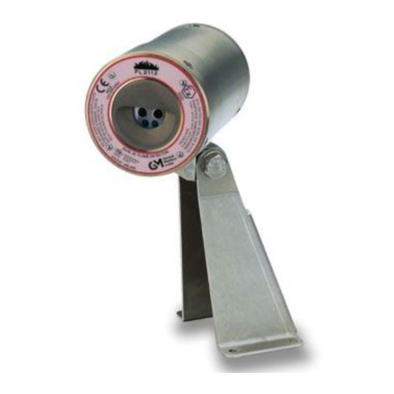
Model FL3112
Digital Frequency Infra-Red (DFIR)
Flame Detector
The information and technical data disclosed in
this document may be used and disseminated
only for the purposes and to the extent specifically
authorized in writing by General Monitors.
Instruction Manual
09/09
General Monitors reserves the right to change
published specifications and designs without prior
notice.
Part No.
MANFL3112-EU
Revision
H/09-09
Advertisement
Table of Contents

Related Manuals for General Monitors FL3112


Summary of Contents for General Monitors FL3112
- Page 1 General Monitors. Instruction Manual 09/09 General Monitors reserves the right to change published specifications and designs without prior notice. Part No. MANFL3112-EU...
-
Page 2: Model Fl3112
Model FL3112 Warranty Statement General Monitors warrants the Model FL3112 to be free from defects in workmanship or material under normal use and service within two years from the date of shipment. General Monitors will repair or replace without charge any equipment found to be defective during the warranty period. -
Page 3: E C Declaration Of Conformity In Accordance With Ec & Atex Directives
EC Directives and relevant standards. General Monitors Ireland Ltd. in order to comply with ATEX, will provide this Instruction Manual in a European Language required to operate the product upon request. Should this be necessary, General Monitors Ireland Ltd. -
Page 4: Table Of Contents
Model FL3112 Table of Contents Page Model FL3112 ....................i Warranty Statement ....................i Warnings ....................i E C Declaration of Conformity in accordance with EC & ATEX Directives ..... ii Table of Contents ....................iii Introduction ....................1 General Description ................... 1 Principle of Operation ................. - Page 5 Modbus Read Status Protocol (Query/Response) ........23 Modbus Write Command Protocol (Query/Response) ......24 Exception Responses and Exception Codes ..........25 FL3112 Command Register Locations ............. 27 FL3112 Operational Mode Command Register Details ......29 Customer Satisfaction Questionnaire ..............36...
-
Page 6: Introduction
Spectral Regions. The General Monitors Model FL3112 is a Digital Frequency Infrared (DFIR) Flame Detector. The Model FL3112 detects the Infrared spectral regions of flame to produce a system which is highly immune to false alarms caused by lightning, arc-welding, hot objects, and other sources of radiation. -
Page 7: Principle Of Operation
IR sources such as hot objects. The inherent flickering of a flame provides the necessary modulation to activate the IR circuit. The Model FL3112 Flame Detector processes these IR signals with a microcomputer and, depending on the version, produces the following outputs: •... - Page 8 FAULT, it may take up to two minutes for the unit to detect an obstruction. Alarm Test The Model FL3112 Flame Detector has a built-in Alarm Test feature. This test may be activated via the serial communications port (see Section 3-4 Terminal Connections).
-
Page 9: Specifications
Response Times and Field of View data have been derived by testing the Model FL3112 Flame Detector with a 1 square foot gasoline fire. One cup of unleaded gasoline on top of a one inch layer of water was ignited for each test. These are typical values and different results may occur depending on the variation of each fire. -
Page 10: Mechanical Specifications
Model FL3112 Mechanical Specifications Enclosure material Material: Bronze AB2 or Stainless Steel Colour: Natural Dimensions: Diameter 3.3 in (8.4 cm) Length 5.4 in (13.7 cm) Weight lbs (2.3 kg) Cable Entries: 2 x M20 or 2 x PG13.5 Electrical Specifications... -
Page 11: Environmental Specifications
Model FL3112 Environmental Specifications Operating temperature range: -40°C to 75°C -40°F to 176°F Storage temperature range: -40°C to 75°C -40°F to 176°F Humidity range: 0 to 100% RH non-condensing Modbus RTU Protocol For detailed information on data format, read commands, write commands, register... -
Page 12: Installation
Detector Field of View Each Model FL3112 Flame Detector has a 120° maximum Cone of Vision. (This Cone has its vertex at the center of the detector, see figure 3-A). -
Page 13: Detector Installation
Cone of Vision. Cable glands and stopping plugs should be installed with the o-rings supplied with the FL3112. It is recommended to fit boots over cable glands to prevent water ingress at the cable-to-gland junction. -
Page 14: Installation Instructions
Installation Instructions 3.5.1 FL3112 Cable Termination • The FL3112 should be installed in accordance with the certification documents and the relevant regulations of the country concerned. • Ensure that approved Exe cable glands are used and installed according to the manufacturer’s instructions. - Page 15 Model FL3112 Figure 3-A FL3112 Field of View...
- Page 16 Model FL3112 Figure 3-B Outline Drawing...
-
Page 17: Terminal Connections
3-D. Figure 3-D Strip Length Four of the six positions on the terminal block have functions which depend on the FL3112 version selected. The remaining two positions are reserved for the power connections. Figure 3-C outlines the terminal block connections by version. - Page 18 A1 ALM Description: This connection is the WARN relay contact. The WARN output is immediate on the Model FL3112. The WARN output can be normally energized or normally de- energized, latching or non-latching. WARN relay contact rating is 1A @ 30VRMS/42.2VPK Resistive.
- Page 19 Figure 3-E Relay Outputs FIELD LOOP OUTPUTS (Figure 3 – F) LP+ and LP- Description: These are the field loop connections to a fire card such as General Monitors’ IN042. The FAULT relay, when energized, inserts a 5600ohms, 2Watt End-Of-Line resistor across these connections.
-
Page 20: User Selectable Options
(re)programmed with the Program Card accessory if necessary. PROGRAM CARD ACCESSORY The Program Card is a small module with a DIP switch which can be read by the FL3112 microprocessor. DIP switch positions 5 to 8 select the options being programmed, such as Sensitivity and Alarm-time-delay, Relay or Return to Factory Default settings. - Page 21 DIP switch positions 1 to 4 are not relevant here WARNING: During the following steps proper anti-static procedures must be observed. Failure to do so may permanently damage the FL3112 electronic circuits and void the warranty. To (re)program, remove the detector from the Base Assembly, disconnect the fly-lead and disconnect the retainer strap at the rear of the Base only.
-
Page 22: Factory Default Settings
Model FL3112 5. Apply +24VDC to connector J3 pins 1 and 2, as shown in the figure, for a minimum of five seconds. This step allows the FL3112 to read the DIP switch settings on the Program Card. 6. Disconnect the +24VDC power supply. - Page 23 Model FL3112 Figure 3-G Front Cap Assembly...
-
Page 24: Maintenance
DO NOT USE A COMMERCIAL GLASS CLEANER OTHER THAN “INDUSTRIAL STRENGTH WINDEX® with Ammonia D”: The lens material is sapphire. The cleaning solution should be General Monitors’ P/N 10272-1 (Industrial Strength Windex® with Ammonia D). -
Page 25: Sensitivity Check
Model FL3112 Sensitivity Check To verify that each detector is functioning correctly, a General Monitors’ Test Lamp and/or the ALARM TEST function (see section 1-2 Principle of Operation – Alarm Test) should be used. See Section 6, Spares & Accessories for details on test lamps. -
Page 26: Trouble Shooting
This section is intended to be a guide in correcting problems which may arise in the field. This section is not all-inclusive, and General Monitors should be contacted for assistance if the corrective actions listed do not eliminate the problem. If equipment or qualified personnel required for various tests are not available it is recommended that the defective unit be returned to General Monitors for repair. -
Page 27: Spares & Accessories
Test Lamps TL103 UV/IR Test Lamp Due to the advanced discrimination in the Model FL3112, the Model TL103 Test Lamp was developed. The General Monitors’ TL103 Test Lamp is a battery operated, rechargeable, test source specifically designed to test General Monitors’ IR Flame Detection Systems. It consists of a high-energy broad band radiation source which emits sufficient energy in the infrared spectra to activate the IR detector. -
Page 28: Modbus Serial Communications
Modbus Read Status Protocol (Query/Response) 7.3.1 Modbus Read Query Message Byte Modbus Range Referenced to FL3112 Slave 1-247* (Decimal) FL3112 ID (Address) Function Code Read Holding Registers Register Address Hi** Not Used by FL3112 Register Address Lo** 00-FF (Hex) FL3112 Command Registers No. -
Page 29: Modbus Write Command Protocol (Query/Response)
7.3.2 Modbus Read Response Message Byte Modbus Range Referenced to FL3112 Slave Address 1-247* (Decimal) FL3112 ID (Address) Function Code Read Holding Registers Byte Count No. of Data Bytes Data Hi 00-FF (Hex) FL3112 Hi Byte Status Data Data Lo... -
Page 30: Exception Responses And Exception Codes
All the Function Codes have a most-significant bit (MSB) of zero (0). In an exception response, the FL3112 sets the MSB of the function code to a one (1). With the function code’s MSB set, the master can recognize the exception response and can process the data field for the exception code from the FL3112 response message. - Page 31 FL3112 was attempting to perform the requested action. Acknowledge The FL3112 has accepted the request and is processing it, but a long duration of time will be required to do so. This response is returned to prevent a timeout error from occurring in the master.
-
Page 32: Fl3112 Command Register Locations
Model FL3112 FL3112 Command Register Locations 7.6.1 Operational Mode Commands R – indicates Read Only Access R/W – indicates Read/Write Access LFF – Low Frequency Fire HFF – High Frequency Fire LFS – Low Frequency Sun Master Refer to Parameter... - Page 33 Model FL3112 R – indicates Read Only Access R/W – indicates Read/Write Access LFF – Low Frequency Fire HFF – High Frequency Fire LFS – Low Frequency Sun Master Refer to Parameter Function Type Scale Access Addr Addr Section Remote Alarm Remotely Activates Alarm...
-
Page 34: Fl3112 Operational Mode Command Register Details
16-bit value. The master scaling is 0 – 65535 Decimal which corresponds to the FL3112 scaling which is 0 – 20mA. 7.7.2 Mode A read returns the fire status mode of the FL3112. Mode Decimal Value Powerup Delay Warn Non-latching Only Warn &... - Page 35 DFIR (Digital Frequency Infra-Red) 3112 7.7.6 Software Rev A read returns the software revision of the FL3112 in 2 ASCII characters (Usually a blank and then a letter revision ex. A, B, C etc). 7.7.7 COPM Fault A read returns the type of Continuous Optical Path Monitoring (COPM) Fault, which is a Fire COPM Fault or Sun COPM Fault.
- Page 36 7.7.9 Address A read returns the address of the FL3112. A write changes the address to the requested address. The range of the address is 1 to 247 (01 to F7 Hex). After the address has been changed to the slave unit, the Modbus communications will cease because the address has changed;...
- Page 37 7.7.10 Baud Rate A read returns the baud rate of the FL3112. A write changes the baud rate to the requested baud rate. After the baud rate has been changed to the addressed unit, the Modbus communications will cease because the baud rate has changed; therefore the master will have to change its baud rate to the slave’s new baud rate in order to restart the...
- Page 38 Model FL3112 7.7.13 Sun COPM Fault Total A read indicates the Total Number of Sun Channel Window or Sensor COPM Faults that occurred in the slave device. This fault is usually caused by a dirty Window or a faulty Fire Channel Sensor or Circuitry.
- Page 39 Model FL3112 7.7.17 Total Receive Errors A read indicates the total Modbus Comm Receive Errors that occurred in the slave device. The maximum count is 255 and then the counter will rollover to zero and begin counting again. The total errors are an accumulation of the individual comm errors listed below.
- Page 40 Model FL3112 7.7.24 Overrun Errors A read indicates the number of Overrun Errors that occurred in the slave device. The maximum count is 255 and then the counter will rollover to zero and begin counting again. Note: An overrun error occurs when the next received byte of data tries to overwrite an existing received data byte which has not been processed.
-
Page 41: Customer Satisfaction Questionnaire
Republic of Ireland. Thank you for your assistance Client Client Order No. ______________________________________________________________________ General Monitors Sales Order No. ________________________________________________________ (Please tick appropriate box) 1. Was the equipment the correct option? 2. Are sensors correct type and range? 3. Is mechanical assembly good? (everything proper fit and tight) 4.
Need help?
Do you have a question about the FL3112 and is the answer not in the manual?
Questions and answers