Table of Contents
Advertisement
M
ODEL
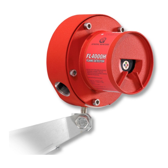
Multi-Spectral Infrared
Flame Detector
FL4000H
The information and technical data disclosed in
this document may be used and disseminated
only for the purposes and to the extent
specifically authorized in writing by General
Monitors.
Instruction Manual
General Monitors reserves the right to change
published specifications and designs without
prior notice.
Part No.
Revision
7-16
MANFL4000NH
MANFL4000NH
N/7-16
Advertisement
Table of Contents

Related Manuals for General Monitors FL4000H


Summary of Contents for General Monitors FL4000H
-
Page 1: Model Fl4000H
General Monitors. Instruction Manual 7-16 General Monitors reserves the right to change published specifications and designs without prior notice. MANFL4000NH Part No. MANFL4000NH... -
Page 2: Model Fl4000H
Model FL4000H This page intentionally left blank... -
Page 3: Table Of Contents
Terminal Connections ......................29 Switch Selectable Options ....................... 36 Powering of the FL4000H ......................38 Power up Grounding of the Test and Relay Reset Lines............38 4.0 MODBUS INTERFACE ......................39 Introduction ..........................39 ... - Page 4 Model FL4000H Baud Rate ..........................39 Data Format ..........................39 Supported Function Codes ...................... 40 Modbus Read Status Protocol (Query / Response) ..............40 Modbus Write Command Protocol (Query / Response) ............41 ...
-
Page 5: Table Of Figures
Figure 4: Bracket Assembly ............................ ix Figure 5: Field Terminations Showing Wiring for Fire Alarm Systems ..............ix Figure 6: FL4000H Front View ..........................14 Figure 7: Test Lamp Flashing Option (Auto-detection) ..................19 Figure 8: Grounding of Test Wire or Modbus Command Options ................ 20 ... - Page 6 Model FL4000H Table of Tables Table 1: Glossary of Terms ..........................12 Table 2: Sample Industry Applications ......................... 15 Table 3: LED sequence for each operating condition..................16 Table 4: Required Tools ............................21 Table 5: Maximum Specified Fields of View at High Sensitivity ................22 ...
-
Page 7: Quick Start Guide
The following procedure should be used in conjunction with the housing diagram below to disassemble the Optical Housing Assy for wiring: Figure 1: FL4000H Housing 1. Loosen the captive screws (A) located on the Optical Housing Assy. 2. Pull the Optical Housing Assy from the Base Housing Assy to separate, gently rock from side to side if necessary to loosen the connector’s grip. -
Page 8: Figure 2: Mounting Instruction
Model FL4000H Figure 2: Mounting Instruction Figure 3: Wall Mounting Assembly viii... -
Page 9: Applying Power To The Detector
Model FL4000H Figure 4: Bracket Assembly Figure 5: Field Terminations Showing Wiring for Fire Alarm Systems Applying Power to the Detector Two light emitting diodes (LED’s) are visible through the window. Immediately upon powering up the detector, both LED’s will start blinking alternately for 15 seconds. The unit will then enter the “Ready”... -
Page 10: Testing The Detector Using A Test Lamp
About This Manual This manual provides instructions for installing, operating, and maintaining the General Monitors (GM) FL4000H Flame Detector. The intended audience includes installation personnel, field service technicians, Modbus programmers, and other technical staff involved in installing and using an FL4000H. -
Page 11: 1.0 Before Installation
Conduit seals or suitably approved Ex d glands must be used to preserve the explosion proof safety of the FL4000H and help prevent ingress of water or gas from the conduit systems. A conduit seal must be installed within 18 inches of the enclosure per NEC regulations. -
Page 12: Glossary Of Terms
Damage to the FL4000H housing where any internal components or protective seals are broken, compromises the safety and usability of the device. An FL4000H with a damaged or open housing should not be used in a hazardous environment. Such damage includes fractures in the housing, cracks in any internal components, or cracks in the protective seals. - Page 13 Model FL4000H Term / Definition Abbreviation Refers to relays being reset to the initial state after “on” condition has Non-Latching been removed National Pipe Thread Over voltage return OV Return Power Supply Common Ground 0VDC Combining with Oxygen Oxidation Printed Circuit Board...
-
Page 14: 2.0 Product Overview
Dual Redundant Modbus RS-485 User Interface (Standard FL4000H Configuration): Provides the capability to operate the FL4000H remotely, using 2 redundant channels. This interface allows the user to remotely change the alarm and warning relay settings, clear selected faults, clear error counters, change baud rates, and change formats for serial communication lines. -
Page 15: Applications
Model FL4000H Applications The FL4000H provides flame detection for a wide range of applications, including, but not limited to the following: Table 2: Sample Industry Applications Industries Sample Applications On and Offshore Platforms Oil and Gas Compressor Buildings Gas Pipelines... -
Page 16: Table 3: Led Sequence For Each Operating Condition
NOTE: The FL4000H will not detect a flame while in Test Mode. The FL4000H has the ability to initiate a special Test Mode, which enables the user to test the response of the unit without the use of a flame source. Once the Test Mode has been activated, the unit will not detect a flame, but rather, responds to GM’s Test Lamp as a simulated flame... - Page 17 NOTE: The Test Lamp sequence is depicted in Figure 7. When the unit is in Operational Mode, the FL4000H recognizes the Test Lamp as a trigger to activate the Test Mode. Within 5-8 seconds of the Test Lamp flashing, the FL4000H will detect the simulated flame source, drop the analog output to 1.5 mA (3.5 mA with HART and small HART...
- Page 18 Model FL4000H After 5-8 seconds of the Test Lamp flashing in Phase 3, the FL4000H goes into Phase 4, indicating 1.5 mA (3.5 mA with HART and small HART current disabled) at the analog output, changing the LED flashing to indicate “Test Mode Running” shown in sequence #8 (Table 3) ...
-
Page 19: Figure 7: Test Lamp Flashing Option (Auto-Detection)
Model FL4000H IGNORED MISUSE CONDITIONS READY GROUND TEST WIRE - HOLD TEST WIRE GROUNDED MODE - RESEND TEST MODE MODBUS COMMAND TEST LAMP FLASHING IN TL103 MODE FOR TL104 OR IN SWITCH POSITIONS 1-3 and 5 FOR Tl105 TEST LAMP... -
Page 20: Figure 8: Grounding Of Test Wire Or Modbus Command Options
Model FL4000H IGNORED MISUSE CONDITIONS REPEAT GROUNDING OF TEST WIRE - HOLD TEST WIRE GROUNDED READY - RESEND TEST MODE MODBUS COMMAND - TEST LAMP FLASHING IN TL103 MODE FOR TL104 MODE OR IN SWITCH POSITIONS 1-3 and 5 FOR Tl105... -
Page 21: 3.0 Installation
If any damage has occurred or there is any discrepancy in the order, please contact General Monitors. Refer to Section 7.0 for contact information. NOTE: Each FL4000H is completely tested at the factory; however, a system check is required upon initial start-up to guarantee system integrity. -
Page 22: Detector Location Guidelines
30 ft (9 m) 90 Maximum specified FOV is the angle at which FL4000H can detect the flame at 50% of the maximum specified range. Maximum specified FOV is the angle at which FL4000H can detect the flame at 50% of the maximum... -
Page 23: Figure 9: Horizontal Fov - N-Heptane - High Sensitivity
Model FL4000H Figure 9: Horizontal FOV – n-Heptane – High Sensitivity. Figure 10: Horizontal FOV – n-Heptane – Medium Sensitivity. -
Page 24: Figure 11: Horizontal Fov - N-Heptane - Low Sensitivity
Model FL4000H Figure 11: Horizontal FOV – n-Heptane – Low Sensitivity. Figure 12: Vertical FOV – n-Heptane – High Sensitivity. -
Page 25: Figure 13: Vertical Fov - N-Heptane - Medium Sensitivity
Model FL4000H Figure 14: Vertical FOV – n-Heptane – Low Figure 13: Vertical FOV – n-Heptane – Medium Sensitivity. Sensitivity. 3.3.2 Optical Sensitivity Range The distance at which the detector will respond to a flame is a function of the intensity of that flame. -
Page 26: Field Wiring Procedure
Avoid conditions of ice build up on the optical detector windows. Complete icing-over of the IR detector window can result in fault conditions. Modulated reflected sunlight shining at the face of the FL4000H reduces flame detection distance. Field Wiring Procedure... -
Page 27: Detector Mounting And Installation
Do not unscrew the field wiring board from the base housing assembly for wiring. CAUTION: Detector Mounting and Installation The FL4000H is enclosed in an explosion proof assembly, which is rated for use in the environments specified in Section 8.3.2. ... -
Page 28: Figure 16: Detector Mounting And Installation
Model FL4000H Figure 16: Detector Mounting and Installation... -
Page 29: Terminal Connections
Model FL4000H Figure 17: Dimensional Drawing Terminal Connections All wire connections are made through the ¾ inch (1.9 cm) NPT openings in the Base Housing to the Terminal Block. The Terminal Block is located in the Base Housing Assembly and accepts 14 AWG (2.08 mm... -
Page 30: Figure 19: Base Housing And Terminal Blocks
Model FL4000H Figure 19: Base Housing and Terminal Blocks Table 7: Terminal Block Connections Terminal Block – P2 Terminal Block – P1 Pin # Description Pin # Description WARN 2 FLT 2 WARN 1 FLT 1 WARN C FLT C... -
Page 31: Figure 20: Terminal Connections
Model FL4000H 3.6.1 Alarm Relay Table 8: Alarm Relay Terminals Terminal Block Connection Block Name User Relay Settings Point Normally De- Normally energized Energized Term 5 ALM2 Alarm NO Alarm NC Term 6 ALM1 Alarm NC Alarm NO Term 7... -
Page 32: Figure 21: Relay Contacts
Description: These connections are to the SPDT WARN relay. The WARN output is immediate on the FL4000H. The WARN output can be normally energized or de-energized, latching, or non-latching. These options are also set via Modbus or by a dipswitch (Section 3.7 ). The WARN relay contact ratings are 8 A @ 250 VAC and 8 A @ 30 VDC. -
Page 33: Table 10: Fault Relay Terminals
P1 terminal 9 (GND), the user can put the unit into a special test mode. When the switch is first closed, the mode is set and the FL4000H goes to 1.5 mA or 3.5 mA with HART and small HART current disabled (ready mode) and remains at this value while detecting the Test Lamp. -
Page 34: Figure 22: Wiring Diagram - Reset Relays, Test Mode, & Alarm Test
Model FL4000H 3.6.7 Alarm Test Terminals Table 13: Alarm Test Terminals Terminal Block Connection Point Block Name Setting Term 4 TEST_IO Test Mode Term 4 RLY_IO Relay Reset By connecting one contact of a DPST, normally open, momentary switch to each of the P1 terminal 4 and P2 terminal 4 simultaneously and the other contact to (GND), the user can perform an Alarm Test (Figure 22). -
Page 35: Table 15: Analog Output Levels
Term 9 Ground (COM) Table 17 shows the power connections for the FL4000H. The supply voltage range is 20 to 36 VDC at the detector (low voltage is detected at 18.5 VDC). The following maximum cable lengths apply for a +24 VDC supply (maximum 20 loop):... -
Page 36: Switch Selectable Options
3.7.1 Time Delay Settings Time delay set via dipswitch guarantees that FL4000H will not go into ALARM mode (20 mA) if the flame source is removed within 50% of set delay time from the start of flame. The unit will... -
Page 37: Figure 23: Dipswitch Location
Model FL4000H Figure 23: Dipswitch Location Table 21: Dipswitch Options Option On/Closed Off/Open High Sensitivity 1 and 2 Medium Sensitivity Low Sensitivity 0-Second Alarm Time Delay 3 and 4 8-Second Alarm Time Delay 10-Second Alarm Time Delay 3 and 4... -
Page 38: Powering Of The Fl4000H
Model FL4000H Powering of the FL4000H After connecting to a 24 VDC power source, the unit will go through a power up delay of approximately 15 seconds. The LEDs will blink in alternating red – green sequence, the unit will output an analog signal of 0mA (3.5 mA with HART or 1.25 mA for HART with small current... -
Page 39: 4.0 Modbus Interface
Communication Slave Address The FL4000H communication slave address is a unique ID used by the Modbus protocol to identify each unit on a multi drop Modbus communication bus. The address may contain the values 1 – 247. There are two communication channels on the FL4000H. Each channel may have a separate slave address. -
Page 40: Supported Function Codes
Function Code 06 (Preset Single Register) is used to write a command to the slave unit. Modbus Read Status Protocol (Query / Response) A master device reads registers from the FL4000H by sending an 8-byte message (Table 24). Table 24: Modbus Read Register(s) Request... -
Page 41: Modbus Write Command Protocol (Query / Response)
Model FL4000H Modbus Write Command Protocol (Query / Response) A master device writes to a FL4000H register by sending a properly formatted 8-byte message (Table 26). Table 26: Modbus Write Register Request Byte Modbus Range Referenced to FL4000H Slave Address... -
Page 42: Table 28: Exception Response
Exception Code Field: In a normal response, the FL4000H returns data and status in the response data field. In an exception response, the FL4000H returns an exception code (describing the FL4000H condition) in the data field. Below is a list of exception codes that are supported by the FL4000H:... -
Page 43: Command Register Locations
Model FL4000H Command Register Locations Table 30: Command Register Locations Register Data Address Parameter Function Data Range Access Type (Hex) Numeric 0-65535 0x0000 Analog Output 0-20mA current output Value (0-20.0 mA) Numeric 0x0001 Operating Mode View operating mode Table 31... - Page 44 Model FL4000H Register Data Address Parameter Function Data Range Access Type (Hex) Clear COPM Fault Reset COPM Counters to Bit 1 = 0x0013 Bit Map Counts zero. Reset Sensor Temperature in Numeric 0x0014 -128… +128 Temperature Degrees C Value 0x0015 –...
- Page 45 Model FL4000H Register Data Address Parameter Function Data Range Access Type (Hex) 0x0032 – Reserved 0x003E Numeric 0x003F Line Voltage Line input voltage * 10.0 Value * 50 - 360 0x0040 – Reserved 0x0046 1 –99 year, Real Time Clock...
- Page 46 Model FL4000H Register Data Address Parameter Function Data Range Access Type (Hex) Numeric 0x00A7 Reserved Reserved Value Warning Event Total Warning Event Numeric 0x00A8 0 - 65535 Count Count Value Running Time Hi for Numeric 0x00A9 Running Time Hi 0 - 65535...
-
Page 47: Command Register Details
0-65535 decimal. 4.10.2 Operating Mode (0x0001) A read returns the present mode of the FL4000H. A write command changes the mode to the requested mode. NOTE: Returns an Exception Code 03 (Illegal Data Value) if an illegal write is requested. -
Page 48: Table 32: Modbus Error Codes
Relay Reset Shorted NOTE: Bits set to “1” when errors occur. 4.10.4 Unit Type (0x0004) A read returns the Modbus identification number for the FL4000H. The identification number for the FL4000H is 3500. 4.10.5 Software Revision (0x0005) A read returns the software revision of the FL4000H as two ASCII characters. -
Page 49: Figure 24: Command Register
NOTE: By grounding the TEST input during the first 1 second of the power up cycle, the FL4000H will enable the DIP Switch Override, enabling the 8-position Dip Switch settings to take effect. The DIP Switch Override bit will be set to zero after approximately 1 second, at which time this input can be released from ground. -
Page 50: Table 33: Com1 Baud Rate
RESET input can be released from ground. 4.10.12 COPM Counts Sensor 1 (0x000D) A read indicates the number of COPM Faults that have occurred for sensor 1 in the FL4000H. Please refer to Section 2.4.2 for more information on COPM and Section 6.0 for troubleshooting tips. - Page 51 Model FL4000H 4.10.13 COPM Counts Sensor 2 (0x000E) A read indicates the number of COPM Faults that have occurred for sensor 2 in the FL4000H. Please refer to Section 2.4.2 for more information on COPM and Section 6.0 for troubleshooting tips.
- Page 52 CRC Errors Low – COM1 and COM2 (0x0025) A read indicates the total number of COM1 or COM2 CRC low byte errors in the FL4000H. The maximum count is 65535, after which the counter resets to zero and begins counting anew.
- Page 53 4.10.33 COM2 Baud Rate (0x0030) A read returns the COM2 baud rate of the FL4000H. A write changes the baud rate to the requested level. After changing the baud rate of the FL4000H, it will be necessary for the controlling or master device to similarly change its own baud rate in order to once again communicate with the FL4000H.
-
Page 54: Table 35: Event Log Clock Time Format
This is used to indicate which of the stored events the user would like to read. There are 4 event logs maintained by the FL4000H unit: Warning events, Alarm events, Fault events, and Maintenance events. Each of these event logs consist of 10 of their most recent occurrences. - Page 55 Model FL4000H 4.10.45 Warning Clock Time: Day, Hour (0x00A4) These registers are described in Table 35 item number 2. 4.10.46 Warning Clock Time: Minute, Second (0x00A5) These registers are described in Table 35 as item number 3. 4.10.47 Reserved (0x00A6) This register returns the value 0.
- Page 56 Model FL4000H 4.10.58 Fault Running Time in Seconds, Hi Word (0x00B1) This register reads the hi word of the running time in seconds when the fault event occurred. This time is in seconds since January 1, 2000. This register should be read before register 0xB2.
- Page 57 Model FL4000H 4.10.71 Reserved (0x00BF) This register returns the value 0. 4.10.72 Total Maintenance Event Counter (0x00C0) This reads the total number of maintenance events have been stored in the unit. 4.10.73 Reset All Event Counters (0x00C1) Writing to this register resets all event counters to zero.
-
Page 58: 5.0 Maintenance
Once correctly installed, the unit requires very little maintenance other than regular sensitivity checks and cleaning of the window. General Monitors recommends that a schedule be established and followed. Do not remove the electronics from the housing. Doing so will void the equipment’s warranty. -
Page 59: Sensitivity Check
ALARM TEST function (Section 3.6.7) should be used. Refer to Section 8.5 for details on Test Lamps. Storage The FL4000H should be stored in a clean, dry area and within the temperature and humidity ranges quoted in Section 8.2.5, Environmental Specifications. -
Page 60: 6.0 Troubleshooting
This section is intended to be a guide to correcting problems, which may arise in the field. General Monitors should be contacted for assistance if the corrective action listed does not eliminate the problem. Defective units should be returned to General Monitors for repair with a complete written description of the problem. -
Page 61: Final Assembly
Model FL4000H Final Assembly Figure 26: FL4000H Cross-Section View... -
Page 62: 7.0 Customer Support
Model FL4000H 7.0 Customer Support Table 37: Locations Area Phone/Email UNITED STATES 26776 Simpatica Circle Phone: +1-949-581-4464. 800-446-4872 Lake Forest, CA 92630 Email: info.gm@MSAsafety.com IRELAND Ballybrit Business Park Galway Republic of Ireland, H91 H6P2 Phone: +353-91-751175 SINGAPORE No. 2 Kallang Pudding Rd. -
Page 63: 8.0 Appendix
These are typical values and different results may occur depending on the variation of each fire. Maximum specified FOV is the angle at which FL4000H can detect the flame at 50% of the maximum specified range. To comply with the directional dependence requirements for EN 54-10:2002, an angle of ± 35°... - Page 64 Model FL4000H 8.2.2 Mechanical Specifications Enclosure material: 316 Stainless Steel Color: Finish: Red Wrinkle Powder Coat 8.2.3 Dimensions Height: 4.3" (109 mm) Diameter: 5.44” (138mm) Base - 3.50" (89 mm) Optical Housing Weight: 7.9 lb. (3.6 kg) 8.2.4 Electrical Specifications Nominal supply voltage: 24 VDC (135 mA, 3.2W Max @ 24 VDC)
-
Page 65: Regulatory Information
IEC 61508 to SIL 3, 2 or 1 Listed as Class 1 for High and Medium Sensitivity and Class 2 for Low Sensitivity 8.3.2 Classification Area and Protection Methods The FL4000H is certified as follows: Protection Method: Explosion proof, Flame proof, Dust-Ignition proof ... -
Page 66: Response To False Stimuli
Model FL4000H Response to False Stimuli The FL4000H detector is immune to a variety of false alarm sources. Below are representative samples of detector response in the presence of false stimuli. Table 38: False Alarm Immunity at High Sensitivity Distance... -
Page 67: Spare Parts And Accessories
Model FL4000H Table 39 shows the response characteristics of the FL4000H in the presence of false alarm sources. The detector is set at a high sensitivity in this illustration. Table 39: Flame Response in the Presence of False Alarm Sources (High Sensitivity) Min. -
Page 68: Table 40: List Of Spare Parts
(3.5 mA with HART and small HART current disabled). While the FL4000H is activated in test mode via the Test Lamp, the FL4000H will detect the TL105 Test Lamp as a flame source. The analog output and relays will respond as if a flame were present. -
Page 69: Figure 27: Rain Guard Installation
8.5.3 Mounting Bracket A mounting bracket is available to mount the FL4000H to a wall, pole, etc. The mounting bracket design allows for optical alignment adjustments when utilizing to a fixed installation. Please refer to Figure 16: Detector Mounting and Installation. -
Page 70: Figure 28: Functional Board Located Under Tl105 Lamp Assembly
Model FL4000H 9.0 Appendix A Rotary Switch shown in position 1 for testing FL3100 Flame Detectors (for FL4000H use position 4) Figure 28: Functional Board Located Under TL105 Lamp Assembly... - Page 71 FL3102 mode FL3110 triggers into alarm FL3110 mode FL3111 triggers into alarm FL3111 mode FL3112 triggers into alarm FL3112 mode FL4000H enters test FL4000H 35 (High Sensitivity) mode 18 (Medium FL4000H enters test FL4000H Sensitivity) mode FL4000H enters test FL4000H...
- Page 72 Model FL4000H ADDENDUM This product may contain hazardous and/or toxic substances. EU Member states shall dispose according to WEEE regulations. For further WEEE disposal information please visit: www.MSAsafety.com All other countries or states: please dispose of in accordance with existing federal, state and local...
Need help?
Do you have a question about the FL4000H and is the answer not in the manual?
Questions and answers