
Related Manuals for Black Box SWI080A-R3


Summary of Contents for Black Box SWI080A-R3
- Page 1 © Copyright 2006. Black Box Corporation. All rights reserved. 1000 Park Drive • Lawrence, PA 15055-1018 • 724-746-5500 • Fax 724-746-0746...
- Page 2 Order toll-free in the U.S.: Call 877-877-BBOX (outside U.S. call 724-746-5500) FREE technical support 24 hours a day, 7 days a week: Call 724-746-5500 or fax 724-746-0746 Mailing address: Black Box Corporation, 1000 Park Drive, Lawrence, PA 15055-1018 Web site: www.blackbox.com • E-mail: info@blackbox.com...
-
Page 4: Federal Communications Commission
FCC AND IC RFI STATEMENTS FEDERAL COMMUNICATIONS COMMISSION INDUSTRY CANADA RADIO FREQUENCY INTERFERENCE STATEMENTS This equipment generates, uses, and can radiate radio frequency energy and if not installed and used properly, that is, in strict accordance with the manufacturer’s instructions, may cause interference to radio communication. It has been tested and found to comply with the limits for a Class A computing device in accordance with the specifications in Subpart B of Part 15 of FCC rules, which are designed to provide reasonable protection against such interference... - Page 5 NETWORK POWER SWITCH JR. NORMAS OFICIALES MEXICANAS (NOM) ELECTRICAL SAFETY STATEMENT INSTRUCCIONES DE SEGURIDAD 1. Todas las instrucciones de seguridad y operación deberán ser leídas antes de que el aparato eléctrico sea operado. 2. Las instrucciones de seguridad y operación deberán ser guardadas para referencia futura.
- Page 6 NOM STATEMENT 10. El equipo eléctrico deber ser situado fuera del alcance de fuentes de calor como radiadores, registros de calor, estufas u otros aparatos (incluyendo amplificadores) que producen calor. 11. El aparato eléctrico deberá ser connectado a una fuente de poder sólo del tipo descrito en el instructivo de operación, o como se indique en el aparato.
- Page 7 NETWORK POWER SWITCH JR. TRADEMARKS USED IN THIS MANUAL Mac is a registered trademark of Apple Computer, Inc. BLACK BOX and the Double Diamond logo are registered trademarks of BB Technologies, Inc. Linux is a registered trademark of Linus Torvalds.
- Page 8 IMPORTANT SAFETY INFORMATION IMPORTANT SAFETY INFORMATION When using this product, follow these basic safety precautions to reduce the risk of fire, electric shock, and injury. 1. Read and understand all instructions. 2. Follow all warnings marked on the product. 3. Unplug this product from the wall outlet before cleaning.
- Page 9 NETWORK POWER SWITCH JR. surface. This product should never be placed in a built-in installation unless proper ventilation is provided. 7. This product should be operated only from the type of power source indicated on the label. If you are not sure of the type of power supply to your home, consult your local power company.
- Page 10 IMPORTANT SAFETY INFORMATION 11. Never push objects of any kind into this product through slots, as they may touch dangerous voltage points or short out parts that could result in fire or electrical shock. Never spill liquid on the product. 12.
- Page 11 NETWORK POWER SWITCH JR. d. If the product does not operate normally by following the operating instructions. Adjust only those controls that are covered by the operating instructions. Improper adjustment of other controls may result in damage and will often require extensive work by a qualified technician to restore the product to normal operation.
-
Page 12: Table Of Contents
CONTENTS Contents Chapter Page 1. Specifications......12 2. Introduction ......13 2.1 Overview. - Page 13 NETWORK POWER SWITCH JR. Contents (continued) Chapter Page 5. Web Browser Operation ....29 5.1 Password Protection ....29 5.2 Control and Status Page .
- Page 14 8. Troubleshooting ......53 8.1 Calling Black Box ..... . 53 8.2 Shipping and Packaging.
-
Page 15: Specifications
NETWORK POWER SWITCH JR. 1. Specifications Software Requirements: Netscape Navigator 3.0 or ® higher; Internet Explorer 3.0 or higher Input Cord: 16 AWG x 3C 10A 250, UL ® /CSA/VDE rated Connectors: Power In: (1) IEC-320 male plug; Power Out: (1) IEC-320 receptacle; Network: (2) RJ-45 10/100BASE-T Ethernet Indicators: LEDs: (2) Link, (1) Power Power: Voltage Range: 105–240 VAC, autosensing;... -
Page 16: Introduction
CHAPTER 2: Introduction 2. Introduction 2.1 Overview The Network Power Switch Jr. is a network-attached, IP-addressed, Web-controlled AC power switch. Anyone with a Web browser can access the switch for power on, off, or power cycle (reboot or power burst). The switch is password-protected for security. -
Page 17: Multiple Control Functions
NETWORK POWER SWITCH JR. • Power up alert devices such as sirens, lamps, messages, or control environmental systems such as heaters, coolers, pumps, etc. Figure 2-1 shows the Network Power Switch Jr. in a typical application. Network Power Switch Jr. PC with Internet or Web Browser... -
Page 18: Auto-Ping
CHAPTER 2: Introduction see Sections 2.3.1 and 6.1. For more information about heartbeat monitor, see Sections 2.3.2 and 6.2. For details about the switch’s remote control program or TCP/IP/Telnet control, see Sections 2.3.3 and 2.3.4. 2.3.1 A Simply put, during auto-ping, the switch pings the network device. - Page 19 NETWORK POWER SWITCH JR. Ping Response Figure 2-2. Local ping: The Network Power Switch Jr. monitors the local device and automatically reboots it if there is no response. Remote Ping Options Put the Network Power Switch Jr. at a central facility to monitor a remote system (see Figure 2-3) and power up an alert (see Figure 2-4) when the remote device no longer responds.
-
Page 20: Heartbeat Monitor
CHAPTER 2: Introduction Response Ping Figure 2-4. Remote ping: The Network Power Switch Jr. monitors the remote device and powers up an alarm when there is no response. 2.3.2 H EARTBEAT ONITOR Like the auto-ping in reverse, heartbeat monitor enables an Ethernet device to send a message (ping) to the switch. -
Page 21: Direct Tcp Control
NETWORK POWER SWITCH JR. multiple switches from one application, eliminating the need for multiple web pages. This also allows for simultaneous control of multiple switches and automation using time of day features. Call Technical Support at 724-746-5500 for details. 2.3.4 D TCP C IRECT ONTROL... -
Page 22: Hardware Installation
CHAPTER 3: Hardware Installation 3. Hardware Installation 3.1 Power Connectors and Switches Figures 3-1 and 3-2 show the power connectors and switches on the Network Power Switch Jr. Figure 3-1. The power input and network connectors are located on the back of the switch. Shipped with 18"... -
Page 23: Ethernet Connections
NETWORK POWER SWITCH JR. CAUTION Disconnect the Network Power Switch Jr. from the AC power source before making any control connections. 3.2 Ethernet Connections The Network Power Switch Jr. supports 10/100 Ethernet using CAT5 unshielded twisted-pair cabling. A two-port built-in hub is included, with two network jacks for access. -
Page 24: Ac Power Connections
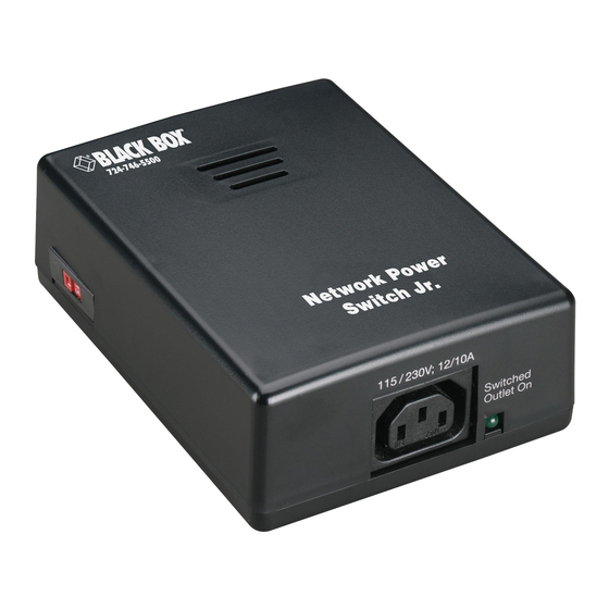
CHAPTER 3: Hardware Installation Network Power Switch Jr. Networked Device (PC Workstation, Router, etc.) 10/100BASE-T Unshielded Network Server Twisted Pair Figure 3-3. Connect a PC to an Ethernet device via the switch. 3.3 AC Power Connections 1. Connect the device to be powered ON and OFF to the IEC receptacle marked “Switched Outlet,”... - Page 25 NETWORK POWER SWITCH JR. 2. If a cord with a different terminating receptacle is required, be sure it is properly rated and meets all the local electrical standards. If the device to be powered uses an IEC-320 receptacle and a detachable power cord, you can use an IEC to IEC extension cord.
- Page 26 CHAPTER 3: Hardware Installation NOTE You can connect the switch to a power strip to allow simultaneous control of multiple devices. CAUTION Make sure that the combined load of all controlled devices does not exceed 10 amps for 210–240 VAC or 12 amps for 105–125 VAC.
-
Page 27: Configuration
NETWORK POWER SWITCH JR. 4. Configuration When configuring the Network Power Switch, Jr., fill in its user settings (MAC address, IP address, subnet mask, and gateway) in Chapter 7. IP Address The Network Power Switch Jr. comes with a factory- installed IP address of 192.168.1.254. - Page 28 CHAPTER 4: Configuration you must check the DHCP server to see what address is assigned to the switch. If you set the IP address using another method, the address becomes static. To return the switch to dynamic addressing using DHCP, change the IP address (using the Web browser) to 0.0.0.0.
- Page 29 NETWORK POWER SWITCH JR. Windows ® (98 and Later) 1. Open a DOS window. (Run Command.) 2. Type the following command, then press <Enter>: arp -s <IP Address><MAC Address> where <IP Address> is the desired IP address (in dotted decimal notation) for the Network Power Switch Jr.
- Page 30 CHAPTER 4: Configuration 4. Delete the entry from the ARP cache by typing arp -d <IP Address> and pressing <Enter>. 5. Ping the switch to confirm that it has been programmed. If the switch fails to respond, repeat steps 2–4. If the problem persists, contact Technical Support.
- Page 31 NETWORK POWER SWITCH JR. Open your browser and access the switch by entering the default (192.168.1.254) or current IP address into your browser’s address window. Enter the password (the factory default is PASS). NOTE The password is case-sensitive; make sure you enter it in all capital letters.
-
Page 32: Web Browser Operation
Figure 5-1). Write down your password and keep it in a secure place in case you forget it. If you forgot your password… Call Black Box Technical Support at 724-746-5500. NOTE The Network Power Switch Jr. is referred to as iBoot in the software that you received. - Page 33 NETWORK POWER SWITCH JR. Figure 5-1. Enter the password in the Setup screen. The Network Power Switch Jr. also uses an inactivity timer for security. When there is no activity for two minutes, the connection is closed and you will need to enter the password again for access.
-
Page 34: Control And Status Page
CHAPTER 5: Web Browser Operation 5.2 Control and Status Page Once you enter the password, the Control and Status page (shown in Figure 5-2) appears. Note that only one person can be connected to the Network Power Switch Jr. at a time. Figure 5-2. - Page 35 NETWORK POWER SWITCH JR. To control the power, click on the appropriate button (Power On, Power Off, or Cycle Power) in the Control and Status page. During power cycling, the power status bar will indicate the status by showing a blue background.
- Page 36 CHAPTER 5: Web Browser Operation factory default for the setup password (as well as the operation password) is PASS. Both passwords can be changed as described in Section 5.1. When you are finished with the Setup page, click on Logout. A confirmation page will appear. See Figure 5-3. If you close your browser window without first clicking on the Logout button, there will be a two-minute delay before you can re-access the switch.
-
Page 37: Setup
NETWORK POWER SWITCH JR. 5.3 Setup Pages The setup pages consist of several sections. Each time you change a setting, click on Apply to save the changes for that section. If you change the IP address via the TCP/IP settings page (Figure 5-5), you must reboot the switch to install the new address. - Page 38 CHAPTER 5: Web Browser Operation Figure 5-4. Set Device settings. Set a power cycle time (0 to 999 seconds). This is the length of time the power will be off during a reboot or during a power burst. Click on Apply. Once you finish setting the device settings, you are ready to set the TCP/IP settings.
-
Page 39: Tcp/Ip Settings
NETWORK POWER SWITCH JR. 5.3.2 TCP/IP S ETTINGS Enter either a new IP address, or enter address 0.0.0.0 to enable automatic IP addressing via DHCP. Enter the subnet mask and gateway. Record these settings in the chart in Chapter 7. Set the HTTP port. Click on Apply after entering all the parameters in the TCP/IP Settings screen. - Page 40 CHAPTER 5: Web Browser Operation Once you click on Apply, then click on the Reboot button that will appear at the top of the page. (See Figure 5-6.) The new IP address will not take effect until the switch is rebooted. Figure 5-6.
- Page 41 NETWORK POWER SWITCH JR. Change the subnet mask if required. To do this, go to the TCP/IP Settings screen shown in Figure 5-5 and enter the appropriate subnet mask. Record this setting in the chart in Chapter 7. The subnet mask will be automatically set if using DHCP.
-
Page 42: Auto-Ping Setup
CHAPTER 5: Web Browser Operation xxx.xxx.xxx.255 (where xxx.xxx.xxx is the subdomain you want to authorize). After changing the port, a reboot is necessary. Consult your network administrator for available port assignments. Click on the Reboot button at the top of the page to install the new port. -
Page 43: Advanced Operation
NETWORK POWER SWITCH JR. 6. Advanced Operation 6.1 Auto-Ping The auto-ping feature allows the Network Power Switch Jr. to automatically detect failed equipment and perform a timed reboot or other power control function (such as turning on an indicator or siren). Set any IP address to be periodically pinged. - Page 44 CHAPTER 6: Advanced Operation Local Ping Network Power Switch Jr. Example: The Network Power Switch Jr. monitors a local device and automatically reboots if there is no response. Local Device Internet or Intranet Remote Ping Example 1: The Network Power Switch Jr. monitors Network Power the network connection Switch Jr.
-
Page 45: Auto-Ping Setup Page
NETWORK POWER SWITCH JR. 6.1.1 A ETUP When auto-ping is enabled, the Network Power Switch Jr. pings the attached Ethernet device. If it gets no response from the device, the switch automatically powers off, powers on, or reboots the device. Figure 6-2 shows how to set up the auto-ping. - Page 46 CHAPTER 6: Advanced Operation Ping Address: Enter the IP address of the device to be pinged. Ping Frequency: Enter 1 to 999 seconds. The ping will go out to the selected device this often. Fail Counter: Enter how many times (1 to 99) the ping needs to fail consecutively before the selected action is taken.
-
Page 47: Using Auto-Ping
NETWORK POWER SWITCH JR. • Power Off—Follow: Upon loss of ping response, the switch will power off. When the ping response returns, the switch will power on. • Power Cycle: Upon loss of ping response, the switch will cycle the power. The switch will wait as long as the ping frequency. -
Page 48: Heartbeat Monitor
CHAPTER 6: Advanced Operation If the fail count has been exceeded, the fail count status will change to disabled. The trigger counter indicates the number of times the auto-ping feature has been triggered. A counter reset button is provided when logging in with the system password. - Page 49 NETWORK POWER SWITCH JR. Heartbeat Network Power Confirmation Switch Jr. Kiosk Figure 6-3. A kiosk generates heartbeat at a regular interval. When the kiosk crashes, the heartbeat stops, and the switch automatically reboots the kiosk. The heartbeat can be generated in any of several ways: •...
-
Page 50: Heartbeat Setup Page
• The heartbeat protocol allows developers to embed this capability directly into their software products. NOTE For heartbeat tools, contact Black Box Technical Support at 724-746-5500. 6.2.1 H EARTBEAT ETUP When heartbeat is enabled, the attached Ethernet device pings the Network Power Switch. - Page 51 NETWORK POWER SWITCH JR. Figure 6-4. Set up the heartbeat via the Heartbeat Monitor page. Enter the ping frequency, fail counter, and desired action in the Heartbeat Monitor page. Frequency: Enter 1 to 999 seconds. If the heartbeat is not received within this time, the counter will reset.
- Page 52 CHAPTER 6: Advanced Operation Fail Counter: Enter how many times (1 to 99) the heartbeat needs to fail before the selected action is taken. Action: Via the drop-down menu next to “Action” in Figure 6-4, select one of the following options: •...
-
Page 53: Using Heartbeat Monitor
A counter reset button is provided when logging in with the system password. 6.2.3 U SING THE EARTBEAT ROGRAM For details on how to use the heartbeat program, contact Black Box Technical Support at 724-746-5500. -
Page 54: Control Programs
CHAPTER 6: Advanced Operation 6.3 Control Programs A remote control program allows you to control the Network Power Switch Jr. directly. For details, contact Tech Support. 6.4 Direct TCP/Telnet Control For application developers, the Network Power Switch Jr. also supports control via direct TCP communications. To control the switch in this manner requires opening a socket to the Network Power Switch Jr. -
Page 55: User Settings
NETWORK POWER SWITCH JR. 7. User Settings Record your Network Power Switch Jr.’s settings here. MAC Address___________________________________ IP Address______________________________________ Subnet Mask____________________________________ Gateway________________________________________ Notes:... -
Page 56: Troubleshooting
CHAPTER 8: Troubleshooting 8. Troubleshooting 8.1 Calling Black Box If you determine that your Network Power Switch Jr. is malfunctioning, do not attempt to alter or repair the unit. It contains no user-serviceable parts. Contact Black Box at 724-746-5500. Before you do, make a record of the history of the problem. -
Page 57: Shipping And Packaging
• Package it carefully. We recommend that you use the original container. • If you are shipping the Network Power Switch Jr. for repair, make sure you include everything that came in the original package. Before you ship, contact Black Box to get a Return Authorization (RA) number.
Need help?
Do you have a question about the SWI080A-R3 and is the answer not in the manual?
Questions and answers