
Related Manuals for STIEBEL ELTRON DEL 18 SL


Summary of Contents for STIEBEL ELTRON DEL 18 SL
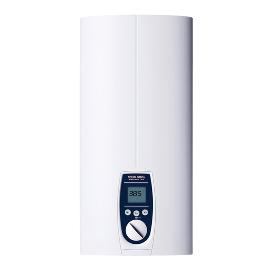
- Page 1 OPERATION AND INSTALLATION E l e ct r on i c a l l y c o n t r o ll e d i n s t a n t a n e o us water heater » DEL 18 / 2 1/ 24 S L e l e c t r o n ic L C D »...
-
Page 2: Table Of Contents
CONTENTS | SPECIAL INFORMATION SPECIAL INFORMATION SPECIAL INFORMATION OPERATION General information The appliance may be used by children aged Safety instructions Other symbols in this documentation 8 and up and persons with reduced physical, Units of measurement sensory or mental capabilities or a lack of Safety experience and know-how, provided that they Intended use... -
Page 3: General Information
OPERATION General information OPERATION 1.2 Other symbols in this documentation Note 1. General information Notes are bordered by horizontal lines above and below the text. General information is identified by the symbol The chapter "Operation" is intended for appliance users shown on the left. -
Page 4: Ce Designation
OPERATION Appliance description 3. Appliance description Where children or persons with limited physical, sensory or men tal abilities are allowed to use this appliance, we The electronically controlled instantaneous water heater recommend a permanent temperature limit. The limit can with automatic output matching maintains a consistent outlet be set by you or a contractor: temperature. -
Page 5: Settings And Displays
OPERATION Settings and displays 4. Settings and displays Set temperature setting range 30 - 60°C (without end-stop) 35°C to 43°C in 0.5°C increments, other temperature ranges in 1°C incerments 4.1 User interface 2 Call up preferred temperatures 3 Set the temperature limit Memory keys M1 and M2 can each be assigned a preferred temperature. -
Page 6: Inlet Temperature Information
OPERATION Cleaning, care and maintenance 6. Troubleshooting 4.3 Inlet temperature information If the inlet temperature is higher than the preferred Fault Cause Remedy temperature, e.g. if water has been preheated by solar The appliance will There is no voltage in the Check the fuses/MCBs in not start despite the appliance. -
Page 7: Installation
OPERATION Safety 8. Appliance description INSTALLATION 8.1 Standard delivery The following are delivered with the appliance: 7. Safety - Wall mounting bracket Only a qualified contractor should carry out installation, - Installation template commissioning, maintenance and repair of the appliance. - 2 twin connectors - Cross-piece 7.1 General safety instructions... -
Page 8: Preparations
OPERATION Preparations Load shedding relay (LR 1-A) Appliance with adjustable connected load The load shedding relay for installation in the distribution The appliance DEL 18/21/24 SL electronic LCD is factory board provides priority control for the instantaneous water set to 21kW. For other outputs, proceed as follows: heater when other appliances, such as electric storage Plug in the coding card according to the selected output;... -
Page 9: Standard Installation
OPERATION Operation 10. Installation Fit the wall mounting bracket. 10.1 Standard installation - Electrical connection in the lower section of the appliance for installation on unfinished walls - Water connection for installation on unfinished walls - For the appliance with adjustable connected load, the middle load is preset. - Page 10 INSTALLATION Installation Push the fixing toggle on to the threaded stud of the wall mounting bracket. Push the back panel of the appliance on to the wall. Turn the fixing toggle 90° clockwise to lock the appliance in place. 1 Plastic profile washer 2 Flow limiter Note Install the blue flow limiter (7.5 l/min) as standard.
-
Page 11: Completing The Installation
INSTALLATION Installation 10.3 Installation options Adjustable connected load Electrical connection from above on unfinished walls With the DEL 18/21/24 SL, 3 connected load stages can be selected. The middle load is preset. With a different connected Electrical connection on finished walls load, proceed as follows: Large cross-section for electrical connection from below Connecting a load shedding relay... - Page 12 INSTALLATION Installation Power cable for finished walls Water installation on finished walls Cut or break out the required entries in the back panel and Suitable pressure-tested taps can be ordered as accessories. appliance cover cleanly (for positions, see chapter "Specification / Dimensions and connections”). If necessary, use a file.
- Page 13 Wall mounting bracket when replacing an appliance fitting the appliance cover When replacing an appliance, you can use an existing wall mounting bracket of a Stiebel Eltron appliance. (except for a DHF instantaneouswater heater). Press the appliance over the threaded stud of the existing 3 3 3 wall mounting bracket.
-
Page 14: Commissioning
INSTALLATION Commissioning 11. Commissioning Pivoting appliance cover You can rotate the appliance cover for undersink installation. WARNING Electrocution Commissioning may only be carried out by an authorised contractor in accordance with the safety regulations. 11.1 Initial start-up electr o ni c comfor electr o nic comfor t... -
Page 15: Recommissioning
INSTALLATION Shutting down the system Appliance handover Explain the appliance function to users and familiarise them with its operation. Make users aware of potential dangers, especially the risk of scalding. Hand over these instructions. 11.2 Recommissioning See chapter "Settings and displays / Following an interruption to the water supply"... -
Page 16: Indicator Options For Led Diagnostic Traffic Light
INSTALLATION Maintenance 13.2 Indicator options for LED diagnostic traffic light Indicator options Illuminates in the event of a fault Yellow Illuminates during heating mode Green Flashing: Appliance is supplied with mains power 13.3 Fault table LED diagnostic Fault Cause Remedy traffic light No display No hot water. -
Page 17: Specification
INSTALLATION Maintenance 15. Specification 15.2 Wiring diagram 3/PE ~ 380-415 V 15.1 Dimensions and connections ≤ 20 1 Heater 2 High limit safety cut-out 3 Safety pressure limiter Priority control with load shedding relay (LR 1-A) See also chapter “Appliance description / Accessories”. Alternative connection options 1 Control cable to contactor of second appliance (e.g. -
Page 18: Dhw Output
Product data complies with EU regulations relating to the Directive on the ecodesign of energy related products (ErP). DEL 18/21/24 SL DEL 27 SL 233678 233679 Manufacturer STIEBEL ELTRON STIEBEL ELTRON Load profile Energy efficiency category Annual power consumption Energy efficiency Default temperature setting °C... -
Page 19: Data Table
INSTALLATION Specification 15.8 Data table DEL 18/21/24 SL DEL 27 SL 233678 233679 Electrical details Rated voltage Rated output kW 16.2/19/21.7 18/21/24 19.4/22.6/25.8 24.4 Rated current A 27.6/29.5/33.3 29/31/35 30.1/32.2/36.3 37.1 Fuse 32/32/35 32/32/35 32/32/40 Phases 3/PE 3/PE Frequency 50/60 50/60 50/- 50/-... - Page 20 Deutschland Verkauf Tel. 05531 702-110 | Fax 05531 702-95108 | info-center@stiebel-eltron.de STIEBEL ELTRON GmbH & Co. KG Kundendienst Tel. 05531 702-111 | Fax 05531 702-95890 | kundendienst@stiebel-eltron.de Dr.-Stiebel-Straße 33 | 37603 Holzminden Ersatzteilverkauf Tel. 05531 702-120 | Fax 05531 702-95335 | ersatzteile@stiebel-eltron.de Tel.
Need help?
Do you have a question about the DEL 18 SL and is the answer not in the manual?
Questions and answers