
Subscribe to Our Youtube Channel
Related Manuals for STIEBEL ELTRON DEL 27 AU


Summary of Contents for STIEBEL ELTRON DEL 27 AU
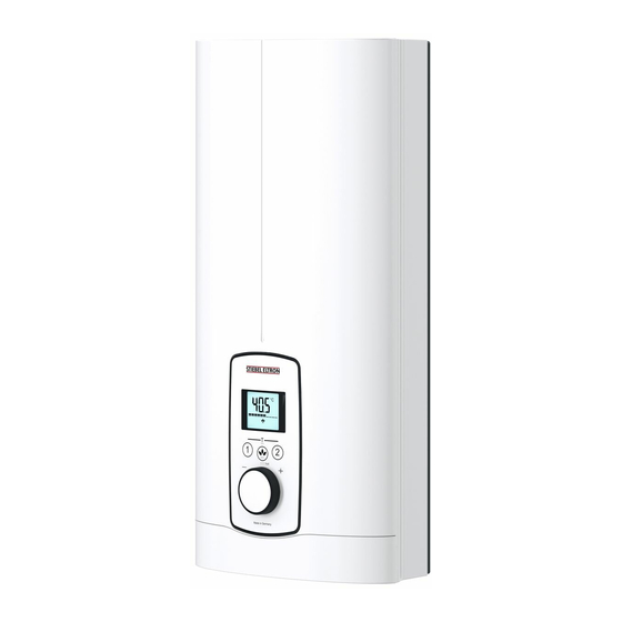
- Page 1 OPERATION AND INSTALLATION Electronically controlled instantaneous water heater » DEL 18 AU » DEL 27 AU Tmax...
-
Page 2: Table Of Contents
CONTENTS | SPECIAL INFORMATION SPECIAL INFORMATION SPECIAL INFORMATION OPERATION General information �����������������������������������������3 - The appliance may be used by children aged 8 Safety instructions ����������������������������������������������� 3 and up and persons with reduced physical, sen- Other symbols in this documentation ����������������������� 3 sory or mental capabilities or a lack of experience Units of measurement ������������������������������������������... -
Page 3: General Information
OPERATION General information OPERATION Other symbols in this documentation Note Notes are bordered by horizontal lines above and below the text. General information is identified by the symbol General information shown on the left. f Read these texts carefully. The chapter "Operation" is intended for appliance users and qual- ified contractors. -
Page 4: Safety
OPERATION Safety Safety CE designation The CE designation shows that the appliance meets all essential Intended use requirements according to the: - Low Voltage Directive This appliance is intended for domestic use. It can be used safely by untrained persons. The appliance can also be used in a non-do- - Electromagnetic Compatibility Directive mestic environment, e.g. -
Page 5: Settings And Displays
OPERATION Settings and displays Settings and displays 1 Set temperature setting range 30 - 60 °C (without end-stop) 35 °C ... 43 °C in 0.5 °C increments, other temperature ranges in 1 °C increments User interface 2 Call up preferred temperatures 3 Set the temperature limit Memory keys M1 and M2 can each be assigned a preferred tem- perature. -
Page 6: Inlet Temperature Information
OPERATION Cleaning, care and maintenance Inlet temperature information If you cannot remedy the fault, notify your qualified contractor. To facilitate and speed up your enquiry, please provide the serial If the inlet temperature is higher than the preferred temperature, number from the type plate (000000-0000-000000): e.g. -
Page 7: Installation
INSTALLATION Safety INSTALLATION Appliance description Standard delivery The following are delivered with the appliance: Safety - Wall mounting bracket Only a qualified contractor should carry out installation, commis- - Installation template sioning, maintenance and repair of the appliance. - 2 plugs - 2 extensions General safety instructions - 2 caps... -
Page 8: Installation Site
INSTALLATION Installation Installation site 10. Installation Material losses 10.1 Standard installation Only install the appliance in rooms free from the risk of - Electrical connection in the lower section of the appliance for frost. installation on unfinished walls - Water connection for installation on finished walls f Always install the appliance vertically near the draw-off - For the appliance with adjustable connected load, the middle point. - Page 9 INSTALLATION Installation Note f Install the blue flow limiter (7.5 l/min) as standard. f Use the brown flow limiter (12 l/min) in the follow- ing instances: - With an increased cold water inlet temperature, e.g. in the case of water preheated by solar energy. - When using the appliance for showering.
-
Page 10: Completing The Installation
INSTALLATION Installation Lower back panel installation f Screw the pre-assembled parts with flat gaskets to the cold 1 Connection pieces delivered in the pack water and DHW pipes of the appliance. 2 Screw f Fit the cold water inlet pipe and the DHW outlet pipe from f Cut open the lower part of the back panel (see illustration). -
Page 11: Installation Options
INSTALLATION Installation f When installing connection pipes that are not offset, break Note off the tabs on the cover guides. This type of connection changes the protection rating of f Click the cover guides into place in the pipe apertures. the appliance. - Page 12 INSTALLATION Installation f Rotate the wall mounting bracket 180° and mount it on the wall. Use the existing drill holes. Installation with offset tiles f Fit the strainer and the plastic profile washer in the tee for the cold water inlet. Damage to the appliance and environment The strainer must be fitted for the appliance to function.
-
Page 13: Commissioning
INSTALLATION Commissioning 11.1 Initial start-up Operation with preheated water You can limit the maximum inlet temperature by installing a cen- tral thermostatic valve. Anti-scalding protection / temperature limit 1 Position 43: Maximum temperature setting 43 °C 2 Position 60: No temperature limit, for temperature setting range, see chapter "Specification / Data table". -
Page 14: Recommissioning
INSTALLATION Shutting down the system 11.2 Recommissioning See chapter "Settings and displays / Following an interruption to the water supply" 12. Shutting down the system f Isolate all poles of the appliance from the power supply. f Drain the appliance (see chapter "Maintenance"). 13. -
Page 15: Indicator Options For Led Diagnostic Traffic Light
INSTALLATION Troubleshooting 13.2 Indicator options for LED diagnostic traffic light Indicator options Illuminates in the event of a fault Yellow Illuminates during heating mode Green Flashing: Appliance is supplied with mains power 13.3 Fault table LED diagnostic Fault Cause Remedy traffic light No display No hot water. -
Page 16: Maintenance
INSTALLATION Maintenance 14. Maintenance 15. Specification 15.1 Dimensions and connections WARNING Electrocution Before any work on the appliance, disconnect all poles from the power supply. ≤ 20 Draining the appliance You can drain the appliance for maintenance work or to protect it from frost. -
Page 17: Wiring Diagram
INSTALLATION Specification 15.2 Wiring diagram Connected load in kW 50 °C DHW output in l/min. Rated voltage Cold water inlet temperature 380 V 400 V 415 V 5 °C 10 °C 15 °C 20 °C 3/PE ~ 380-415 V 10.1 11.0 12.0 12.2 13.2 13.5 13.6 14.2... -
Page 18: Data Table
INSTALLATION Specification 15.7 Data table DEL 18 AU DEL 27 AU 233741 233742 Electrical data Rated voltage Rated output 16.2 19.4 23.5 Rated current 24.7 35.6 37.7 38.9 Fuse/MCB rating Phases 3/PE 3/PE Frequency 50/60 50/60 50/- 50/- 50/- 50/- ≥... -
Page 19: Environment And Recycling
Who gives the warranty 9.3. The name, address and contact details (such as phone The warranty is given by Stiebel Eltron (Aust) Pty Ltd number and e-mail address) of the owner; (A.B.N. 82 066 271 083) of Unit 4/8 Rocklea Drive, Port Mel- 9.4. - Page 20 The Stiebel Eltron warranty for the unit is in addition to any b) connection to an incorrect water supply; rights and remedies you may have under the Australian c) connection to water from a bore, dam or swimming Consumer Law.
- Page 21 NOTES www.stiebel-eltron.com DEL AU|...
- Page 22 NOTES | DEL AU www.stiebel-eltron.com...
- Page 23 NOTES www.stiebel-eltron.com DEL AU|...
- Page 24 Deutschland Verkauf Tel. 05531 702-110 | Fax 05531 702-95108 | info-center@stiebel-eltron.de STIEBEL ELTRON GmbH & Co. KG Kundendienst Tel. 05531 702-111 | Fax 05531 702-95890 | kundendienst@stiebel-eltron.de Dr.-Stiebel-Straße 33 | 37603 Holzminden Ersatzteilverkauf Tel. 05531 702-120 | Fax 05531 702-95335 | ersatzteile@stiebel-eltron.de Tel.
Need help?
Do you have a question about the DEL 27 AU and is the answer not in the manual?
Questions and answers