Table of Contents
Advertisement
SIMATIC NET
S7-1200 - Telecontrol
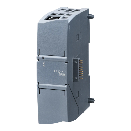
CP 1242-7 GPRS V2
Operating Instructions
C79000-G8976-C311-00
05/2014
C79000-G8976-C311-00
Preface
Application and properties
Configuration examples
LEDs and connectors
Installation, connecting up,
commissioning
Notes on configuration and
operation
Configuration and
programming
Service and maintenance
Technical specifications
Dimension drawings
Approvals
Accessories
References
1
2
3
4
5
6
7
8
A
B
C
D
Advertisement
Table of Contents

Related Manuals for Siemens CP 1242-7 GPRS V2


Summary of Contents for Siemens CP 1242-7 GPRS V2
- Page 1 Preface Application and properties Configuration examples SIMATIC NET LEDs and connectors S7-1200 - Telecontrol Installation, connecting up, CP 1242-7 GPRS V2 commissioning Notes on configuration and operation Operating Instructions Configuration and programming Service and maintenance Technical specifications Dimension drawings Approvals...
- Page 2 Note the following: WARNING Siemens products may only be used for the applications described in the catalog and in the relevant technical documentation. If products and components from other manufacturers are used, these must be recommended or approved by Siemens. Proper transport, storage, installation, assembly, commissioning, operation and maintenance are required to ensure that the products operate safely and without any problems.
-
Page 3: C79000-G8976-C311
Preface Validity of this manual This document contains information on the following product: CP 1242-7 GPRS V2 Order number 6GK7 242-7KX31-0XE0 Hardware product version 1 Firmware version V2.0 The device is the communications processor for data transmission using GPRS for the SIMATIC S7-1200. -
Page 4: Commissioning
Replaced documentation none Current manual release on the Internet You will also find the current version of this manual on the Internet pages of Siemens Automation Customer Support under the following entry ID: <TODO> A link to the current manual for the version history of SIMATIC NET program blocks can be found in the references in the Appendix of this manual. - Page 5 In addition to the product documentation, the comprehensive online information platform of Siemens Automation Customer Support supports at any time and at any location in the world. You will find the Service & Support pages on the Internet at the following address: http://support.automation.siemens.com/WW/llisapi.dll?func=cslib.csinfo2&aktprim=99&lang=en...
- Page 6 (http://www.automation.siemens.com/partner/guiwelcome.asp?lang=en) SITRAIN - Siemens training for automation and industrial solutions With over 300 different courses, SITRAIN covers the entire Siemens product and system spectrum in the field of automation and drive technology. Apart from the classic range of courses, we also offer training tailored for individual needs and a combination of different teaching media and sequences, for example self-learning programs on CD-ROM or on the Internet.
-
Page 7: Table Of Contents
Table of contents Application and properties ......................9 Connecting the S7-1200 to a GSM network ................9 Applications ............................10 Other properties of the CP ...................... 11 Performance data ........................11 Requirements for operation ....................13 Configuration examples ........................ 15 LEDs and connectors ........................ - Page 8 Table of contents Service and maintenance ......................49 Diagnostics ..........................49 Downloading firmware ......................50 Module replacement ........................50 Technical specifications ....................... 53 Dimension drawings ........................55 Approvals ........................... 57 Accessories..........................63 Antennas..........................63 TS Gateway ..........................65 References ..........................69 Index ............................71 CP 1242-7 V2 Operating Instructions, 05/2014, C79000-G8976-C311-00...
-
Page 9: Application And Properties
The CP 1242-7 GPRS V2 can receive and send SMS messages. The communications partner can be a mobile phone or an S7-1200. The CP 1242-7 GPRS V2 is suitable for use in industry worldwide and supports the following frequency bands:... -
Page 10: Applications
The function is not dependent on the operating mode of the CP. Via the CP 1242-7 GPRS V2, the CPU of a remote S7-1200 station can receive SMS messages from the GSM network or send messages by SMS to a configured mobile phone or an S7-1200. -
Page 11: Other Properties Of The Cp
Application and properties Other properties of the CP Other services and functions of the CP 1242-7 GPRS V2 Time-of-day synchronization of the CP via the Internet You can set the time on the CP as follows: – In "Telecontrol" mode, the time of day is transferred by the telecontrol server. The CP uses this to set its time. - Page 12 Application and properties Number of simultaneous connections in "Telecontrol" mode 1 reserved connection to the telecontrol server, for example for TeleService When connection establishment is active also: Max. 5 telecontrol connections (TCON_WDC) Max. 5 UDP connections (send only) Number of simultaneous connections in "GPRS direct" mode A total of maximum 4 connections Of which: Max.
-
Page 13: Requirements For Operation
Maximum 1000 frames Requirements for operation Hardware requirements Apart from the CP 1242-7 GPRS V2 in the remote S7-1200, the following hardware is also required: A CPU with firmware version as of V2.0 An external antenna for the CP 1242-7 GPRS V2, see Accessories (Page 63) In the "Telecontrol"... - Page 14 – The contract must allow the assignment of public IP addresses. – If there is to be direct communication between GPRS stations ("GPRS direct" mode), the GSM network provider must assign fixed IP addresses to the CP 1242-7 GPRS V2 and forward the frames to the destination subscribers.
-
Page 15: Configuration Examples
Figure 2-1 Sending messages by SMS from an S7-1200 station A SIMATIC S7-1200 with a CP 1242-7 GPRS V2 can send messages by SMS to a mobile phone or a configured S7-1200 station. The function can also be used to send diagnostics SMS messages to an authorized mobile phone. - Page 16 Figure 2-2 Communication between S7-1200 stations and a control center In telecontrol applications, SIMATIC S7-1200 stations with a CP 1242-7 GPRS V2 communicate with a control center via the GSM network and the Internet. The "TELECONTROL SERVER BASIC" (TCSB) application is installed on the telecontrol server in the master station.
- Page 17 In this configuration, two SIMATIC S7-1200 stations communicate directly with each other using the CP 1242-7 GPRS V2 via the GSM network. Each CP 1242-7 GPRS V2 has a fixed IP address. The relevant service of the GSM network provider must allow this.
- Page 18 Configuration examples 1.5 Requirements for operation TeleService with telecontrol server The connection runs via the telecontrol server. The engineering station and telecontrol server are connected via the Intranet (LAN) or Internet. The telecontrol server and remote station are connected via the Internet and via the GSM network.
- Page 19 Configuration examples 1.5 Requirements for operation TeleService without a telecontrol server The connection runs via the TeleService gateway. The connection between the engineering station and the TeleService gateway can be local via a LAN or via the Internet. Figure 2-5 TeleService via GPRS in a configuration with TeleService gateway CP 1242-7 V2 Operating Instructions, 05/2014, C79000-G8976-C311-00...
- Page 20 Configuration examples 1.5 Requirements for operation CP 1242-7 V2 Operating Instructions, 05/2014, C79000-G8976-C311-00...
-
Page 21: Leds And Connectors
LEDs and connectors Opening the housing Location of the display elements and the electrical connectors The LEDs for the detailed display of the module statuses are located behind the upper cover of the module housing. The socket for the power supply is located on the top of the module. The connector for the external antenna is located on the bottom of the module. -
Page 22: Leds
LEDs and connectors 3.2 LEDs LEDs LEDs of the module The module has various LEDs for displaying the status: LED on the front panel The "DIAG" LED that is always visible shows the basic statuses of the module. LEDs below the upper cover of the housing The LEDs below the upper cover provide more detailed information on the module status. - Page 23 LEDs and connectors 3.2 LEDs Display of the operating and communication status The LED symbols in the following tables have the following significance: Table 3- 3 Meaning of the LED symbols Symbol LED status ON (steady light) Flashing Not relevant The LEDs indicate the operating and communications status of the module according to the following scheme: Table 3- 4...
- Page 24 LEDs and connectors 3.2 LEDs Table 3- 5 Display schemes for detailed module statuses DIAG NETWORK CONNECT SIGNAL TELESERVI Meaning QUALITY (red / green) (red / green) (green) (yellow / (green) green) No connection to the GPRS service in the GSM network Connection exists to the GPRS service in the GSM network...
-
Page 25: Electrical Connections
LEDs and connectors 3.3 Electrical connections Electrical connections Power supply The 3-pin socket for the external 24 V DC power supply is located on the top of the module. The matching plug ships with the product. You will find the pin assignment of the socket in section Pin assignment of the socket for the external power supply (Page 34). - Page 26 LEDs and connectors 3.3 Electrical connections CP 1242-7 V2 Operating Instructions, 05/2014, C79000-G8976-C311-00...
-
Page 27: Installation, Connecting Up, Commissioning
Installation, connecting up, commissioning Important notes on using the device Safety notices on the use of the device The following safety notices must be adhered to when setting up and operating the device and during all work relating to it such as installation, connecting up, replacing devices or opening the device. - Page 28 Installation, connecting up, commissioning 4.1 Important notes on using the device WARNING Replacing components EXPLOSION HAZARD SUBSTITUTION OF COMPONENTS MAY IMPAIR SUITABILITY FOR CLASS I, DIVISION 2 OR ZONE 2. WARNING Requirements for the cabinet/enclosure When used in hazardous environments corresponding to Class I, Division 2 or Class I, Zone 2, the device must be installed in a cabinet or a suitable enclosure.
-
Page 29: Installing And Commissioning The Cp
Installation, connecting up, commissioning 4.2 Installing and commissioning the CP Overvoltage protection NOTICE Protection of the external power supply If power is supplied to the module or station over longer power cables or networks, the coupling in of strong electromagnetic pulses onto the power supply cables is possible. This can be caused, for example by lightning strikes or switching of higher loads. - Page 30 Installation, connecting up, commissioning 4.2 Installing and commissioning the CP Step Execution Notes and explanations Turn off the power supply to the station. Release the slide for the SIM card on the bottom of the CP by gently pressing the release pin.
- Page 31 30 mm 15 mm CM 1242-5 (PROFIBUS slave) CP 1242-7 GPRS V2 (GPRS CP) 30 mm 15 mm * Width B: The distance between the edge of the housing and the center of the hole in the DIN rail mounting clip DIN rail mounting clips All CPUs, SMs, CMs and CPs can be installed on the DIN rail in the cabinet.
- Page 32 Installation, connecting up, commissioning 4.2 Installing and commissioning the CP Procedure for installation and commissioning NOTICE Installation location The module must be installed so that its upper and lower ventilation slits are not covered, allowing adequate ventilation. Above and below the device, there must be a clearance of 25 mm to allow air to circulate and prevent overheating.
- Page 33 Installation, connecting up, commissioning 4.2 Installing and commissioning the CP Table 4- 2 Procedure for installation and connecting up Step Execution Notes and explanations Mount the CP on the DIN rail and connect it to Use a 35 mm DIN rail. the module to its right.
-
Page 34: Pin Assignment Of The Socket For The External Power Supply
Installation, connecting up, commissioning 4.3 Pin assignment of the socket for the external power supply Pin assignment of the socket for the external power supply Figure 4-2 Socket for the external 24 VDC power supply (view from above) Table 4- 3 Pin assignment of the socket for the external power supply Labeling Function... -
Page 35: Notes On Configuration And Operation
Modes and communications partners of the CP 1242-7 GPRS V2 Modes and communications partners of the CP For communication with the CP 1242-7 GPRS V2 via GPRS, the CP is set to one of the following modes: Telecontrol This CP mode allows the GPRS station to exchange data with a telecontrol server. -
Page 36: Connection Modes And Connection Establishment
The possible communications services and security functions (for example VPN) depend on what is offered by the network provider. Possible communications partners of the GPRS station with a CP 1242-7 GPRS V2 in "GPRS direct" mode are: – A subscriber that can be reached by the CP via an IP address (for example S7-1200 with CP 1242-7 GPRS V2) –... -
Page 37: The Wake-Up Sms
Notes on configuration and operation 5.3 The wake-up SMS Triggering connection establishment for permanent stations ("Telecontrol" mode) In the "Telecontrol" mode, the permanent connection to the telecontrol server is established when the station starts up. If the connection is interrupted, the CP attempts to re-establish the connection at 15 minute intervals. - Page 38 – Text for the wake-up SMS message for establishing a connection to the substitute telecontrol server: TELECONTROL BACKUP The configuration of the telecontrol server for the CP 1242-7 GPRS V2 is set in STEP 7 in "Telecontrol interface > Operating mode > main or substitute telecontrol server". Note Wake-up with a mobile phone One of the texts listed above can be used in a wake-up SMS message.
-
Page 39: Calling A Teleservice Connection
Calling a TeleService connection Requirement for the engineering station The STEP 7 project with the CP 1242-7 GPRS V2 is stored on the engineering station. Requirement for switching the connection The request for connection establishment is triggered by the engineering station. To switch the connection to the remote station, a telecontrol server or a TeleService gateway is required. -
Page 40: Connection Monitoring, Data Buffering, Acknowledgement
Notes on configuration and operation 5.5 Connection monitoring, data buffering, acknowledgement Working with TeleService Note Loading only in offline mode Loading software and blocks with TeleService via GPRS by calling the function "Load to device" only works when no TeleService connection is established. Canceling a TeleService connection when calling online dialogs An existing TeleService connection is canceled when you attempt to access an additional station or a node. -
Page 41: Connection Monitoring Time
Notes on configuration and operation 5.5 Connection monitoring, data buffering, acknowledgement three times 20 s redial delay + three times the connection monitoring time configured for the CP (time until the arrival of the TCP acknowledgement from the communications partner) Note Depending on your contract, costs may result from each connection establishment attempt. -
Page 42: Frame Buffer And Acknowledgement
ERROR and STATUS condition codes. The sending of the frame is not automatically repeated. Recipient: CP 1242-7 GPRS V2 - "GPRS direct" mode If the network interface acknowledges that the frame was sent successfully, it sends the message "TC_SEND" DONE. -
Page 43: Data Transfer Between Communications Partners
1. Copy the database file from the following directory of the main system: Programdata > Siemens > Automation > TCS Basic > Data > "Smsc.sqlite" 2. Insert the database file at the same location in the file system of the substitute system. -
Page 44: Reading Out Time By Cpu
RDREC. The parameters of the RDREC need to have the following settings: As the logical address, enter the hardware identifier of the CP 1242-7 GPRS V2. MLEN Enter a length of 12 bytes. -
Page 45: Configuration And Programming
Requirements for operation (Page 13). You can configure a maximum of three CMs/CPs per station. If you insert several modules of the type CP 1242-7 GPRS V2 in an S7-1200, you can, for example, establish redundant communications paths. - Page 46 Configured PIN and PIN on the SIM card must match. If you enter the PIN of the SIM card of the CP 1242-7 GPRS V2 incorrectly during STEP 7 configuration and download the station, the CP stores the wrong PIN. An incorrectly entered PIN is transferred by the CP only once so that the SIM card is not locked.
- Page 47 Configuration and programming 6.2 Information required for configuration Information required in "Telecontrol" mode The following information is required for the STEP 7 configuration of the CP 1242-7 GPRS Address of the telecontrol server – IP address – Name of the telecontrol server that can be resolved by DNS –...
- Page 48 6.2 Information required for configuration CP parameter for configuring the telecontrol server The following parameters from the STEP 7 configuration of the CP 1242-7 GPRS V2 are also required for the configuration of the telecontrol server: Address and port of the telecontrol server...
-
Page 49: Service And Maintenance
SMS message with the following text from this telephone: CPDIAG The diagnostics SMS message that is then sent contains the following data of the S7 station: Firmware version of the CP 1242-7 GPRS V2 Mode of the CPU (RUN / STOP) Status of the GPRS connection... -
Page 50: Downloading Firmware
New firmware versions If a new firmware version is available for the module, you will find this on the Ethernet pages of the Siemens Automation Customer Support under the following ID: <TODO> On the Internet page, select the "Entry list" tab and the "Download" entry type. You will find the firmware file and a description of the procedure there. - Page 51 Service and maintenance When the station starts up again, the new CP reads the project data from the CPU. If you replace a module, remember to take the SIM card from the old module and insert it in the new CP. WARNING Read the system manual "S7-1200 Programmable Controller"...
- Page 52 Service and maintenance CP 1242-7 V2 Operating Instructions, 05/2014, C79000-G8976-C311-00...
-
Page 53: Technical Specifications
Technical specifications Table 8- 1 Technical specifications of the CP 1242-7 GPRS V2 Technical specifications Order number 6GK7 242-7KX31-0XE0 Wireless interface Antenna connector Amount Design SMA socket Nominal impedance 50 ohms Frequency bands GPRS 850, 900, 1800, 1900 MHz Maximum transmit power GSM 850, class 4 +33 dBm ±2dBm... - Page 54 Dimension drawings Technical specifications Permitted ambient conditions Ambient temperature During operation with the rack 0 °C to +55 °C installed horizontally During operation with the rack 0 °C to +45 °C installed vertically During storage -40 °C to +70 °C During transportation -40 °C to +70 °C Relative humidity...
-
Page 55: Dimension Drawings
Dimension drawings Note All dimensions in the drawings are in millimeters. Figure A-1 CP 1242-7 GPRS V2 - front view CP 1242-7 V2 Operating Instructions, 05/2014, C79000-G8976-C311-00... - Page 56 Dimension drawings Figure A-2 CP 1242-7 GPRS V2 - side view left Figure A-3 CP 1242-7 GPRS V2 - view from above CP 1242-7 V2 Operating Instructions, 05/2014, C79000-G8976-C311-00...
-
Page 57: Approvals
SIMATIC NET products are regularly submitted to the relevant authorities and approval centers for approvals relating to specific markets and applications. If you require a list of the current approvals for individual devices, consult your Siemens contact or check the Internet pages of Siemens Automation Customer Support: 45605894 (http://support.automation.siemens.com/WW/view/en/45605894) - Page 58 (R&TTE) EU Directive 2002/95/EC (RoHS) The EC Declaration of Conformity is available for all responsible authorities at: Siemens Aktiengesellschaft Industry Automation Industrielle Kommunikation SIMATIC NET Postfach 4848 D-90327 Nürnberg...
- Page 59 Approvals C.1 Antennas ATEX approval ATEX approval: II 3 G Ex nA II T4 Test number: KEMA 10 ATEX 0166X EN 60079-0:2006: Potentially explosive atmosphere - general requirements EN 60079-15:2005: Electrical apparatus for explosive gas atmospheres; type of protection 'n' Over and above this, the following conditions must be met for the safe deployment of the CP: Install the modules in a suitable enclosure with degree of protection of at least IP54 to EN 60529 and take into account the environmental conditions for operation of the...
- Page 60 Approvals C.1 Antennas brouillage radioélectrique subi, même si le brouillage est susceptible d'en compromettre le fonctionnement. Mexico approval “La operación de este equipo está sujeta a las siguientes dos condiciones: (1) es posible que este equipo o dispositivo no cause interferencia perjudicial y (2) este equipo o dispositivo debe aceptar cualquier interferencia, incluyendo la que pueda causar su operación no deseada.”...
-
Page 61: Environmental Conditions
Approvals C.1 Antennas Standards and test specifications The device meets the following standards and test specifications. The test criteria for the device are based on these standards and test specifications. Industrial environments The CP was developed for use in industrial environments. Application Requirements for emissions Requirements for immunity... - Page 62 Approvals C.1 Antennas Environmental conditions - transportation and storage EN 60068-2-14, Test Na, temperature shock -40°C to +70°C, dwell time 3 hours, 2 cycles EN 24180-2 Free fall 0.3 m in dispatch packaging Atmospheric pressure 1 080 to 660 hPa (corresponding to an altitude of -1 000 to 3 500 m) Environmental conditions - operation Ambient temperatures / air humidity 0 °C to 55 °C for horizontal installation of the rack...
-
Page 63: Accessories
SMA connector, including installation bracket, screws, wall plugs You will find detailed information in the device manual. You will find this on the Internet on the pages of Siemens Industrial Automation Customer Support under the following entry ID: 23119005 (http://support.automation.siemens.com/WW/view/en/23119005) CP 1242-7 V2... - Page 64 You will find detailed information in the device manual. You will find this on the Internet on the pages of Siemens Industrial Automation Customer Support under the following entry ID: 48729835 (http://support.automation.siemens.com/WW/view/en/48729835) Technical specifications of the ANT794-4MR GSM/GPRS antenna...
-
Page 65: Ts Gateway
Accessories C.2 TS Gateway ANT794-4MR Construction Antenna with fixed HF cable and SMA male connector Dimensions (D x H) in mm 25 x 193 Weight Antenna incl. cable 310 g Fittings 54 g Installation With supplied bracket Technical specifications of the flat antenna ANT794-3M Order number 6NH9870-1AA00 Mobile wireless networks... - Page 66 Accessories C.2 TS Gateway What functions does the TeleService gateway provide? The TeleService gateway has the following functions: Switching station The TeleService gateway is a PC in the network that serves as the intermediary between the engineering station and remote S7 station. Since a firewall is normally closed for connection requests from the outside, a switching station between the remote station and the engineering station is required.
- Page 67 – Connection to LAN or Internet access for connecting to the engineering station – Internet access for connecting to the remote S7 station – Installation of the "TS Gateway" application The software ships with the CP 1242-7 GPRS V2 (see product DVD). CP 1242-7 V2 Operating Instructions, 05/2014, C79000-G8976-C311-00...
- Page 68 Accessories C.2 TS Gateway CP 1242-7 V2 Operating Instructions, 05/2014, C79000-G8976-C311-00...
-
Page 69: References
References Where to find Siemens documentation You will find the order numbers for the Siemens products of relevance here in the following catalogs: – SIMATIC NET Industrial Communication / Industrial Identification, catalog IK PI – SIMATIC Products for Totally Integrated Automation and Micro Automation, catalog... - Page 70 References D.2 /2/ SIMATIC NET TELECONTROL SERVER BASIC Operating Instructions Siemens AG entry ID: 50898745 (http://support.automation.siemens.com/WW/view/en/50898745) SIMATIC NET TS Gateway Operating Instructions Siemens AG Entry ID: 48548898 (http://support.automation.siemens.com/WW/view/en/48548898) CP 1242-7 V2 Operating Instructions, 05/2014, C79000-G8976-C311-00...
-
Page 71: Index
Index Hazardous area, 27 Acknowledgment of frames, 42 ATEX, 28 Inserting/removing a SIM card, 29 Authorized phone numbers, 37 Instructions, 13 Inter-station communication, 9 CDMA, 9 Connection abort, 42 Load to device, 40 Connection establishment active/passive, 11 Connection interrupted, 36 Connection modes, 36 Connection resources, 11 Main gateway, 66... - Page 72 Index Safety notices, 27 Server password, 47 SIMATIC NET glossary, 5 SMS gateway, 38 Standards, 61 STEP 7 version, 13 Substitute gateway, 66 Support, 5 Telecontrol (mode), 35 Telecontrol connection, 12 Telecontrol server, 35 TELECONTROL SERVER BASIC, 35 TeleService, 46 TeleService gateway, documentation, 14 TeleService via GPRS, 10 Test specifications, 61...
Need help?
Do you have a question about the CP 1242-7 GPRS V2 and is the answer not in the manual?
Questions and answers