Advertisement
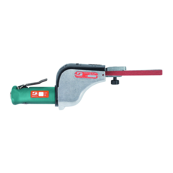
Dynafile
Models:
14000 – 20,000 RPM
14010 – Versatility Kit
Read and understand this tool manual before operating your air tool. Follow all safety rules for the protection of operating personnel
as well as adjacent areas. Always operate, inspect and maintain this tool in accordance with the American National Safety Institute
(ANSI) Safety Code for Portable Air Tools – B186.1. For additional safety information, refer to Safety Requirements for the Use, Care
and Protection of Abrasive Wheels – ANSI B7.1, Code of Federal Regulation – CFR 29 Part 1910, European Committee for Standards
(EN) Hand Held Non-Electric Power Tools – Safety Requirements and applicable State and Local Regulations.
Read and understand tool manual before
work starts to reduce risk of injury to
operator, visitors, and tool.
Eye protection must be worn at all times,
eye protection to conform to ANSI Z87.1.
Respiratory protection to be used when exposed to
contaminants that exceed the applicable threshold
limit values required by law.
Carefully Read all instructions before operating or servicing any Dynabrade
Products offered by Dynabrade are not to be modified, converted or otherwise alerted from the original design without expressed written consent from Dynabrade, Inc.
Tool Intent: Dynafile
®
abrasive belt machine replaces tedious hand filing and sanding and can be used for grinding, deburring, blending and polishing. Can be used on most
materials including metal, plastic, fiberglass, composites, rubber, glass and stone.
Training: Proper care, maintenance, and storage of your tool will maximize its performance.
• Employer's Responsibility – Provide Dynafile
Accessory Selection:
• Abrasive/accessory RPM (speed) rating MUST be approved for AT LEAST the tool RPM rating.
• Before mounting an accessory, visually inspect for defects. Do not use defective accessories.
• Mount only recommended accessories. See back page of manual and Dynabrade catalog.
• Follow tool specifications before choosing size and type of accessory.
• Only use recommended fittings and air line sizes. (See tool Machine Specifications table.)
Warning: Always wear eye protection. Operator of tool is responsible for following: accepted eye, face, respiratory, hearing and body protection.
Caution: Hand, wrist and arm injury may result from repetitive work, motion and overexposure to vibration.
®
Air Tool Manual – Safety, Operation and Maintenance
SAVE THIS DOCUMENT, EDUCATE ALL PERSONNEL
WARNING
SAFETY LEGEND
WARNING
WARNING
WARNING
SAFETY INSTRUCTIONS
®
Do Not Use Tool For Anything Other Than Its Intended Applications.
®
operators with safety instructions and training for safe use of tools and accessories.
OPERATING INSTRUCTIONS
(continued on next page)
Practice safety requirements. Work alert,
have proper attire, and do not operate tools under
the influence of alcohol or drugs.
Ear protection to be worn when exposure to sound,
exceeds the limits of applicable Federal, State or
local statues, ordinances and/or regulations.
Air line hazard, pressurized supply lines and flexible
hoses can cause serious injury. Do not use damaged,
frayed or deteriorated air hoses and fittings.
Abrasive Power Tool.
Parts Page Reorder No. PD02•01R
Effective January, 2002
For Serial No. 2C1000 and Higher
WARNING
WARNING
WARNING
Advertisement

Related Manuals for Dynabrade Dynafile 14000


Summary of Contents for Dynabrade Dynafile 14000
- Page 1 Carefully Read all instructions before operating or servicing any Dynabrade ® Abrasive Power Tool. Products offered by Dynabrade are not to be modified, converted or otherwise alerted from the original design without expressed written consent from Dynabrade, Inc. Tool Intent: Dynafile ®...
- Page 2 (6.2 Bar) Valve • Ideally the air supply should be free from moisture. • Dynabrade Air Power Tools are designed to Incorporating a refrigerated air dryer after the operate at 90 PSIG (6.2 Bar/620 kPa) maximum compressor and drain valves at each tool station...
-
Page 3: Maintenance Instructions
• Refer to Dynabrade's Warning/Safety Operating Instructions Tag (Reorder No. 95903) for safety information. After maintenance is performed on tool, add a few drops of Dynabrade Air Lube (P/N 95842) to the air line and start the tool a few times to lubricate air motor. -
Page 4: Table Of Contents
Dynafile ® Index Key No. Part # Description Complete Assembly Breakdown 1 Contact Arm Assembly (See pages 8-11) 2 95218 Knob Assembly 3* 11420 Idler Arm Assy., Includes: 95070 Threaded Insert 11040 Spring 4 11359 Tension Spring 5* 95162 Screw (2) 6* 11011 Idler Wheel Assy. - Page 5 7. Check clearance between rotor and bearing plate by using a .001" feeler gauge. Clearance should be at .001" to .0015". Adjust clearance by repeating steps 1-4 with different shim if necessary. 8. Once proper rotor/gap clearance is achieved, install well lubricated 01011 Blades (4) into rotor slots. Dynabrade air lube P/N 95842 is recommended for lubrication.
-
Page 6: Contact Arm Assembly
Important: Motor should now be tested for proper operation at 90 PSIG. If motor does not operate properly or operates at a higher RPM than marked on the tool, the tool should be serviced to correct the cause before use. Before operating, place 2-3 drops of Dynabrade Air Lube (P/N 95842) directly into air inlet with throttle lever depressed. -
Page 7: Knob Assembly
This service chart is published as a guide to expectant life of component parts. The replacement levels are based on average tool usage over one year. Dynabrade Inc. considers one year usage to be 1,000 hours or 50% of a man year. Parts included in motor tune-up kit are identified by High Wear and Medium Wear items. -
Page 8: Bearing
Dynafile ® Standard Contact Arm Assemblies Part Abrasive Contact Wheel Contact Wheel Contact Wheel Bearing Number Belt Size Description Comments Assembly Only (2) Req. Shaft 11178 1/2" x 34" 5/16" Dia. x 3/8" W Steel 9" Reach 11068 11067 11051 11054 11179 1/2"... - Page 9 Dynafile ® Standard Contact Arms Standard Contact Arms allow for a 4" workable reach. 11212 File round openings as small as 7/16". 11219 No platen due to offset design. 45 PSIG maximum. Grind radiuses, slack polish. Offset for slack polishing Belt Size: 1/4"...
- Page 10 Dynafile ® Specialized Contact Arms Designed to solve tough production problems. 11237 and 11238 Turbine Blade Arms 45 PSIG maximum. 11255 Cross-Bow Arm • I.D. polishing or deburring with one 180° wrist turn. • Deburr leading radius of 1" to 4" round openings. 11237: 1/4"...
-
Page 11: Drive Wheel
Contact Arm Assembly/Disassembly Instructions 11279 CONTACT WHEEL SHAFT 11275 CONTACT WHEEL SHAFT ADHESIVE REMOVAL TOOL PIPE CLEANER PRESS FIT SLIP FIT INSERT INTO BORE OF BEARING 11271 WHEEL POSITION BLOCK BEARING REMOVE CONTACT ARM FROM MACHINE. PRESS CONTACT WHEEL SHAFT OUT OF CONTACT ARM. MOISTEN TIP OF PIPE CLEANER WITH CONTACT WHEEL SHAFT ADHESIVE AND APPLY TO ID OF BEARINGS BEFORE INSTALLING PROPER SHAFT. -
Page 12: Lock Ring
Visit Our Web Site: www.dynabrade.com Email: Customer.Service@Dynabrade.com DYNABRADE, INC., 8989 Sheridan Drive • Clarence, NY 14031-1490 • Phone: (716) 631-0100 • Fax: 716-631-2073 • International Fax: 716-631-2524 DYNABRADE EUROPE S.àr.l., Zone Artisanale • L-5485 Wormeldange—Haut, Luxembourg • Telephone: 352 76 84 94 1 • Fax: 352 76 84 95 1 ©...
Need help?
Do you have a question about the Dynafile 14000 and is the answer not in the manual?
Questions and answers