Advertisement
Quick Links
REG. DESIGN NO: 3016251
Installation Safety Notes.....................................................................................................................2
Parts List.............................................................................................................................................4
Installation Instructions.......................................................................................................................6
Product Dimensions..........................................................................................................................14
B-Tech Contact Details.....................................................................................................................16
INSTALLATION TOOLS REQUIRED
13mm (1/2") &
10mm (2/5")
spanner or socket
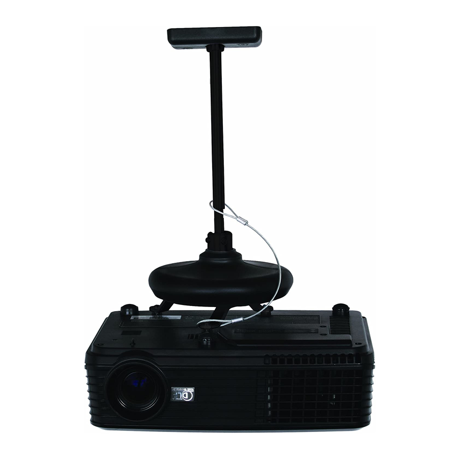
B-TECH AUDIO VIDEO MOUNTS
BT881
UNIVERSAL PROJECTOR CEILING MOUNT
INSTALLATION GUIDE & PARTS LIST
This Pack Contains 1 Mount
PLEASE KEEP THIS FOR FUTURE REFERENCE
CONTENTS
Drill
Crosshead
screwdriver
www.btechavmounts.com
FEATURES
● Suitable for projectors up to 10kg (22lbs)
● Mounts projector only 115mm (4.5") from ceiling or 280mm (11")
with supplied extension rod
● +/-90º tilt adjustment, +/-90º roll adjustment and 360º swivel
● Easy to adjust and fix projector in position
● Steel safety wire for extra security
● Maximum distance between any two fixing points
on projector: 340mm (13.4")
● Suitable for projectors with M2.5, M3, M4, M5 and M6 fixings
● Simple installation with all mounting hardware included
8mm (5/16") masonry bit
or 5mm (3/16") wood bit
Pencil
Stud finder
(optional)
Advertisement

Related Manuals for B-Tech BT881

Summary of Contents for B-Tech BT881
-
Page 1: Table Of Contents
Parts List.............................4 Installation Instructions........................6 Product Dimensions..........................14 B-Tech Contact Details........................16 INSTALLATION TOOLS REQUIRED 13mm (1/2") & Pencil Stud finder Drill Crosshead 8mm (5/16") masonry bit 10mm (2/5") (optional) or 5mm (3/16") wood bit screwdriver spanner or socket B-TECH AUDIO VIDEO MOUNTS www.btechavmounts.com... -
Page 2: Installation Safety Notes
Do not attempt to install this product until all instructions and warnings have been read and properly understood. Please keep these instructions for future reference. B-Tech International Limited, its distributors and dealers are not liable or responsible for damage or injury caused by improper installation, improper use or failure to observe these safety instructions. In such cases, all guarantees will expire. - Page 3 Niniejszy produkt musi być zamontowany na odpowiedniej powierzchni, a podczas użytkowania nie wolno przekraczać podanego maksymalnego obciążenia. A B-Tech International Ltd. recomenda que a instalação deste produto seja efectuada por um instalador de AV profissional ou outra pessoa devidamente habilitada. A B-Tech International Ltd. e os seus distribuidores e concessionários não são responsáveis por danos ou lesões causados por uma instalação incorrecta.
-
Page 4: Parts List
BT881 PARTS LIST Suitable for loads up to 10kg (22lbs) Ceiling Plate Assembly Interface Assembly... - Page 5 PART NAME CEILING PLATE SPACER BALL JOINT SHORT EXTENSION ROD LONG EXTENSION ROD ADAPTOR COVER PLATE (FOR PART 1) SECURITY CABLE M8 NUT M8 SPRING WASHER M6 X 6mm GRUB SCREW M6 X 10mm GRUB SCREW CAROUSEL LONG LEG SHORT LEG CAROUSEL COVER PLATE M8 X 20mm HEX SCREW THUMB WHEEL...
-
Page 6: Installation Instructions
INSTALLATION INSTRUCTIONS Loosen the grub screws, take the adaptor and cover plates off the ceiling plate. OPTIONAL - LONG CEILING DROP i. Disassemble, remove ii. Re-assemble, replacing short extension rod part 4 with part 5... - Page 7 i. Fix ceiling plate to the ceiling. ONLY USE PART A3 WHEN FIXING TO CONCRETE CEILINGS ii. Slide on the cover plates.
- Page 8 Attach interface assembly to projector. i. Attach legs to projector.
- Page 9 ii. Attach the adaptor to carousel and place on legs. iii. Attach the carousel to the legs. Using quick release hand wheels or using secure dome nuts and spacers.
- Page 10 Attach the projector to the ceiling plate assembly and secure with parts 12.
- Page 11 Attach the security cable. i. Un-screw one interface screw to attach security cable. ii. Loop the security cable over the leg.
- Page 12 iii. Re-attach the leg to the projector...
- Page 13 Adjusting the projector. To tilt/roll and swivel, loosen parts 11, adjust and re-tighten. 90° 360° Slide cover plates onto interface assembly.
-
Page 14: Product Dimensions
BT881 PRODUCT DIMENSIONS 92mm 50mm 3.6" 2" 12mm (0.5") THESE INSTRUCTIONS ARE INTENDED AS A GUIDE ONLY AND B-TECH ACCEPTS NO LIABILITY FOR THE ACCURACY OF THE INFORMATION CONTAINED IN THIS DOCUMENT. - Page 15 PRODUCT DIMENSIONS CEILING PLATE 88mm 3.5" 14.5mm 0.6" 45mm 1.8" 59mm 2.3" 74mm 2.9" INTERFACE PLATE 340mm 13.4" THESE INSTRUCTIONS ARE INTENDED AS A GUIDE ONLY AND B-TECH ACCEPTS NO LIABILITY FOR THE ACCURACY OF THE INFORMATION CONTAINED IN THIS DOCUMENT.
-
Page 16: B-Tech Contact Details
©2010 Bennett Technologies Limited. All rights reserved. B-Tech Audio Video Mounts is a division of Bennett Technologies Limited. B-Tech, Better By Design and Mountlogic are registered trademarks of Bennett Technologies Limited. All other brands and product names are trademarks of their respective owners.
Need help?
Do you have a question about the BT881 and is the answer not in the manual?
Questions and answers