Advertisement
Quick Links
Description
Demonstration Circuit DC2064A is a bidirectional cell
balancer using two
LTC
3300-1
®
balancing of up to 12 Li-Ion batteries. The board uses the
LTC6803-2
multi-cell addressable battery stack monitor to
measure cell voltages and two LTC3300-1 ICs to provide
active cell balancing. The demonstration circuit uses a two
window GUI developed for the DC2064A. One window is
a modified version of the GUI for the LTC6803-2 and also
contains a tab to control the LTC3300-1 ICs through the
DC590B USB Serial controller and the second window
performance summary
Battery Voltage Range
Stack Voltage
Average Battery Balancing Charge Current (12 Cell)
Average Battery Balancing Discharge Current (12 Cell)
Average Battery Balancing Charge Current (6 Cell)
Average Battery Balancing Discharge Current (6 Cell)
Balancing Efficiency
*The battery voltage range may be expanded to 2.5V-4.5V by changing resistor R
The demo board's average balancing current is adjustable up to 4A by scaling and installing new values of RS1A and RS1B through RS12A and RS12B.
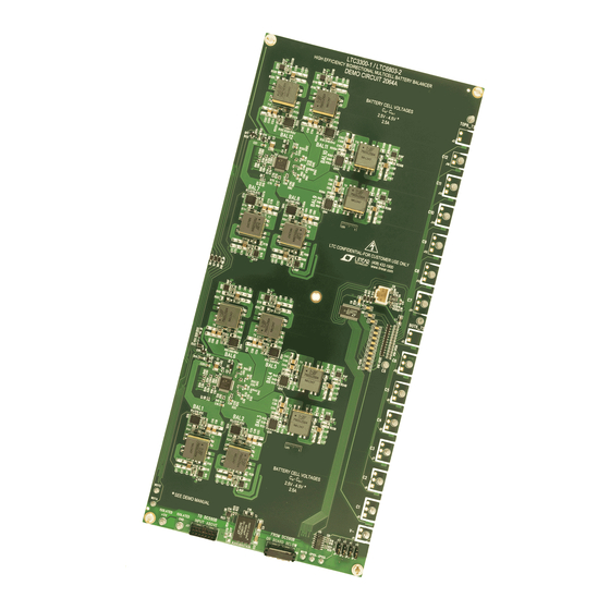
BoarD photo
ICs to achieve active cell
Specifications are at T
DEMO MANUAL DC2064A
LTC3300-1/LTC6803-2
Bidirectional Cell Balancer
reports the status of the LTC3300-1 devices. All the
functions of the LTC6803-2 GUI are supported except
that cell balancing is achieved through the LTC3300-1
ICs by transferring charge from one to six batteries per
LTC3300-1 to the stack or from the stack to one to six
batteries per LTC3300-1.
Design files for this circuit board are available at
http://www.linear.com/demo/DC2064A
L, LT, LTC, LTM, Linear Technology and the Linear logo are registered trademarks of Linear
Technology Corporation. All other trademarks are the property of their respective owners.
= 25°C
A
3.2V to 4.5V (2.5V to 4.5V)*
60V Max
2.6A (Typ) (4A)*
2.4A (Typ) (3.6A)*
2.2A (Typ) (3.3A)*
2.4A (Typ) (3.6A)*
92% (Typ)
to 19.1k and resistor R
TONS
TONP
to 29.4k.
dc2064afa
1
Advertisement

Related Manuals for Linear LTC3300-1


Summary of Contents for Linear LTC3300-1
- Page 1 LTC3300-1 ICs through the L, LT, LTC, LTM, Linear Technology and the Linear logo are registered trademarks of Linear DC590B USB Serial controller and the second window Technology Corporation. All other trademarks are the property of their respective owners.
- Page 2 DEMO MANUAL DC2064A Description Power Stage Discharge Efficiency Power Stage Charge Efficiency 6-CELL 6-CELL 12-CELL 12-CELL CELL VOLTAGE (V) CELL VOLTAGE (V) Figure 1. DC2064A Size 5.5" × 12.2" dc2064afa...
-
Page 3: Operating Principle
GUI, one window based on the DC1652A GUI to control off. The charge in the primary inductor is transferred to the LTC6803-2 with a tab to control the LTC3300-1 for the secondary inductor which is connected across the battery balancing and the second window to display the 12-cell pack. - Page 4 Figure 6. Start Cell Voltage Read Box measured on the cells when balancing. To avoid the To access the LTC3300-1 screen, click on the LTC3300-1 program from suspending balancing from an OV or UV tab in the upper left of the LTC6803-2 GUI window.
- Page 5 “None”, the remaining times to balance are recalculated, The LTC3300-1 GUI allows the user to program the balancer then the remaining cells continue to balance until the next to charge or discharge each cell for a specific amount of cell(s) have completed.
- Page 6 Stack voltage measurements should voltage and the primary side and secondary side current be made at the BOT6_TS and TOP6_TS turrets and their sense inputs to the LTC3300-1. return path turret. Figures 16 through 19 are cell and stack currents taken To calculate cell balancer efficiency use the expressions over a range of cell voltages from 2.6V to 4.0V.
- Page 7 DEMO MANUAL DC2064A Quick start proceDure 12 Cell Discharge 6 Cell Discharge Table 2. Typical 12 Cell Discharge Data Table 4. Typical 6 Cell Discharge Data Cell I (A) Stack I (A) Frequency (kHz) Efficiency Cell I (A) Stack I (A) Frequency (kHz) Efficiency 2.444...
- Page 8 DEMO MANUAL DC2064A Quick start proceDure 12-CELL 12-CELL 6-CELL 6-CELL CELL VOLTAGE (V) CELL VOLTAGE (V) Figure 16. Cell Discharge Current Figure 18. Cell Charge Current 0.50 0.50 0.45 0.45 6-CELL 0.40 6-CELL 0.40 0.35 0.35 0.30 0.30 12-CELL 0.25 0.25 12-CELL 0.20...
- Page 9 DEMO MANUAL DC2064A Quick start proceDure Two Board Setup and Operation: must be connected to the PC USB port and the bottom DC2064A board first and then the top DC2064A board As a result of communication latency to the PC, the system may be connected.
- Page 10 DEMO MANUAL DC2064A Quick start proceDure Figure 21. 24 Cell Interconnected Stacks dc2064afa...
- Page 11 Hex Address Box. voltage drop which will minimize the current in the parallel diode within the LTC3300-1 as well as surviving the fusing current of the 7A fuses on the DC2064A. Two overvoltage detection circuits have been added to the...
- Page 12 V of the lowest LTC3300-1 and from the top cell to when selecting the capacitance value. If a connection is the cell below it to insure an equal voltage across all cells lost during balancing, the differential voltage seen by the when the battery stack is initially connected.
- Page 13 DEMO MANUAL DC2064A Quick start proceDure Figure 24. DC2064A LTC6803-2 Setup Screen dc2064afa...
- Page 14 G11P 1µF 4.7µF I11P 0603 0805 C10K G10P 1µF 4.7µF I10P 0603 0805 1µF 4.7µF 0603 0805 1µF 4.7µF – 0603 0805 1µF 4.7µF 0603 0805 4.7µF WDTC 0805 DC2064a F26 Figure 26. Bypass Capacitors on the Top LTC3300-1 dc2064afa...
- Page 15 DEMO MANUAL DC2064A Quick start proceDure Figure 27. DC2064A LTC3300-1 Setup Screen with Timed Balance Controls Figure 28. DC2064A LTC3300-1 Status GUI Screen dc2064afa...
- Page 16 DEMO MANUAL DC2064A Quick start proceDure System Setup Requirements: LFP or Li-Ion Battery ≥ 10AHr Internal Resistance < 30mΩ Recommended Battery Simulator: Power Supply 2V to 5.0 V ±10A Interconnect Resistance < 25mΩ Figure 29. Proper Measurement Equipment Setup for Bidirectional Cell Balancer Note: All connections from equipment should be Kelvin connected directly to the Board Pins which they are connected to on this diagram and any input, or output, leads should be twisted pair, where possible.
- Page 17 DEMO MANUAL DC2064A Quick start proceDure System Setup Requirements: LFP or Li-Ion Battery ≥ 10AHr Internal Resistance < 30mΩ Recommended Battery Simulator: Power Supply 2V to 5.0 V ±10A Interconnect Resistance < 25mΩ Figure 30. Proper Equipment Setup for Cell Balancer Efficiency Measurements dc2064afa...
- Page 18 DEMO MANUAL DC2064A Quick start proceDure System Setup Requirements: LFP or Li-Ion Battery ≥ 10AHr Internal Resistance < 30mΩ Recommended Battery Simulator: Power Supply 2V to 5.0 V ±10A Interconnect Resistance < 25mΩ Figure 31. Proper Equipment Setup for Minimum Number of Cell Efficiency Measurements dc2064afa...
- Page 19 DEMO MANUAL DC2064A Quick start proceDure System Setup Requirements: LFP or Li-Ion Battery ≥ 10AHr Internal Resistance < 30mΩ Recommended Battery Simulator: Power Supply 2V to 5.0 V ±10A Interconnect Resistance < 25mΩ Figure 32. Configuring the Board for Six Batteries dc2064afa...
- Page 20 DEMO MANUAL DC2064A Quick start proceDure System Setup Requirements: LFP or Li-Ion Battery ≥ 10AHr Internal Resistance < 30mΩ Recommended Battery Simulator: Power Supply 2V to 5.0 V ±10A Interconnect Resistance < 25mΩ Figure 33. Configuring the Board for Seven Batteries dc2064afa...
- Page 21 DEMO MANUAL DC2064A Quick start proceDure System Setup Requirements: LFP or Li-Ion Battery ≥ 10AHr Internal Resistance < 30mΩ Recommended Battery Simulator: Power Supply 2V to 5.0 V ±10A Interconnect Resistance < 25mΩ Figure 34. Configuring the Board for Eight Batteries dc2064afa...
- Page 22 DEMO MANUAL DC2064A Quick start proceDure System Setup Requirements: LFP or Li-Ion Battery ≥ 10AHr Internal Resistance < 30mΩ Recommended Battery Simulator: Power Supply 2V to 5.0 V ±10A Interconnect Resistance < 25mΩ Figure 35. Configuring the Board for Nine Batteries dc2064afa...
- Page 23 DEMO MANUAL DC2064A Quick start proceDure System Setup Requirements: LFP or Li-Ion Battery ≥ 10AHr Internal Resistance < 30mΩ Recommended Battery Simulator: Power Supply 2V to 5.0 V ±10A Interconnect Resistance < 25mΩ Figure 36. Configuring the Board for Ten Batteries dc2064afa...
- Page 24 DEMO MANUAL DC2064A Quick start proceDure System Setup Requirements: LFP or Li-Ion Battery ≥ 10AHr Internal Resistance < 30mΩ Recommended Battery Simulator: Power Supply 2V to 5.0 V ±10A Interconnect Resistance < 25mΩ Figure 37. Configuring the Board for Eleven Batteries dc2064afa...
-
Page 25: Schematic Diagrams
DEMO MANUAL DC2064A schematic Diagrams dc2064afa... - Page 26 DEMO MANUAL DC2064A schematic Diagrams dc2064afa...
- Page 27 DEMO MANUAL DC2064A schematic Diagrams WDTC WDTA dc2064afa...
- Page 28 DEMO MANUAL DC2064A schematic Diagrams dc2064afa...
- Page 29 DEMO MANUAL DC2064A schematic Diagrams dc2064afa...
-
Page 30: Pcb Layout
DEMO MANUAL DC2064A pcB layout Figure 43. Top Silk Screen dc2064afa... - Page 31 DEMO MANUAL DC2064A pcB layout Figure 44. Bottom Silk Screen dc2064afa...
- Page 32 DEMO MANUAL DC2064A pcB layout Figure 45. Layer 1 dc2064afa...
- Page 33 DEMO MANUAL DC2064A pcB layout Figure 46. Layer 2 dc2064afa...
- Page 34 DEMO MANUAL DC2064A pcB layout Figure 47. Layer 3 dc2064afa...
- Page 35 DEMO MANUAL DC2064A pcB layout Figure 48. Layer 4 dc2064afa...
-
Page 36: Parts List
CENTRAL SEMI, CMPDM8002A T1-T12 TRANSFORMER, 1:1, 3.0µH, 10.8A WURTH, 750312504 U1,U2 IC, SMT, BIDIRECTIONAL BATTERY BALANCER LINEAR, LTC3300ILXE-1#PBF IC, EEPROM 2KBIT, 400KHZ, 8TSSOP MICROCHIP TECH. 24LC025-I/ST IC, SMT, OP AMP LINEAR, LT6004IMS8#PBT IC, GATE NAND QUAD 2-PIN 14-SO FAIRCHILD, MM74HC00M... - Page 37 Information furnished by Linear Technology Corporation is believed to be accurate and reliable. However, no responsibility is assumed for its use. Linear Technology Corporation makes no representa- tion that the interconnection of its circuits as described herein will not infringe on existing patent rights.
- Page 38 Linear Technology Corporation (LTC) provides the enclosed product(s) under the following AS IS conditions: This demonstration board (DEMO BOARD) kit being sold or provided by Linear Technology is intended for use for ENGINEERING DEVELOPMENT OR EVALUATION PURPOSES ONLY and is not provided by LTC for commercial use. As such, the DEMO BOARD herein may not be complete in terms of required design-, marketing-, and/or manufacturing-related protective considerations, including but not limited to product safety measures typically found in finished commercial goods.
Need help?
Do you have a question about the LTC3300-1 and is the answer not in the manual?
Questions and answers