Table of Contents
Advertisement
Quick Links
DESCRIPTION
Demonstration circuit 2830A features the
a 40A high efficiency, switch mode step-down µModule
regulator which is controlled by the
precision, bidirectional, 7-Bit current DAC with PMBus
interface. The LTC7106 is used to adjust the output volt-
age of the LTM4636 by way of the PMBus. The LTM4636's
input voltage range is from 4.7V to 15V and the output
voltage range is from 0.6V to 3.3V. De-rating is necessary
for certain VIN, VOUT, frequency and thermal conditions.
The LTC7106 requires an input voltage from 2.5V to 5.5V
and on DC2830A it's powered directly from the DC1613A
dongle. The LTC7106 provides three ranges of IDAC out-
put current: Nominal Range (–64µA to 63µA), Range High
(–256µA to 252µA) and Range Low (–16µA to 15.75µA).
The nominal range is optimized with the highest accuracy.
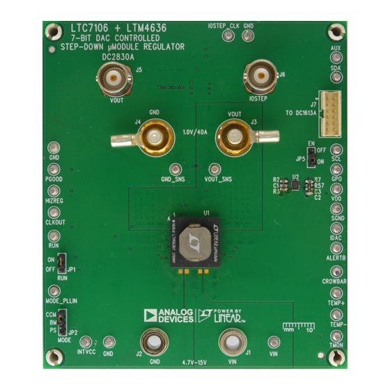
BOARD PHOTO
DEMO MANUAL DC2830A
7-Bit DAC with PMBus Controlled
Step-Down µModule Regulator
LTM
4636EY,
It is recommended that users design the resistor divider
®
using the nominal range of the IDAC setting.
®
LTC
7106EDDB, a
®
To explore the power system management features of
the LTC7106, download the GUI software LTpowerPlay
onto your PC and use ADI's I
DC1613A to connect to the board. LTpowerPlay allows the
user to reconfigure the part on-the-fly, view IDAC current
value and fault status.
The LTM4636 and LTC7106 data sheets must be read in
conjunction with this demo manual prior to working on
or modifying demo circuit DC2830A.
Design files for this circuit board are
All registered trademarks and trademarks are the property of their respective owners.
LTC7106 and LTM4636
2
C/SMBus/PMBus Dongle
®
available.
Rev 0
1
Advertisement
Table of Contents

Related Manuals for Linear ANALOG DEVICES LTC7106


Summary of Contents for Linear ANALOG DEVICES LTC7106
- Page 1 DEMO MANUAL DC2830A LTC7106 and LTM4636 7-Bit DAC with PMBus Controlled Step-Down µModule Regulator DESCRIPTION Demonstration circuit 2830A features the 4636EY, It is recommended that users design the resistor divider ® a 40A high efficiency, switch mode step-down µModule using the nominal range of the IDAC setting. ®...
-
Page 2: Performance Summary
DEMO MANUAL DC2830A PERFORMANCE SUMMARY Specifications are at T = 25°C PARAMETER CONDITIONS UNITS LTM4636 Input Voltage Range Output Voltages 1.0 ±2.3% Maximum Continuous Output Current De-rating is necessary for certain operating conditions. See data sheet for details. Operating Frequency Efficiency = 12V, V = 1.0V, I... -
Page 3: Ltpowerplay Software Gui
LTC3882, LTC3815, LTC2974 and LTC2978. The soft- downloaded from: ware supports a variety of different tasks. You can use http://www.analog.com/en/design-center/ LTpowerPlay to evaluate Linear Technology ICs by con- ltpower-play.html. necting to a demo board system. LTpowerPlay utilizes the To access technical support documents for LTC Digital DC1613A USB-to-SMBus controller to communicate with Power Products visit Help. - Page 4 DEMO MANUAL DC2830A LTpowerPlay SOFTWARE GUI Figure 3. LTpowerPlay Main Interface for LTC7106 Rev 0...
- Page 5 DEMO MANUAL DC2830A LTpowerPlay QUICK START PROCEDURE The following procedure describes how to use LTpowerPlay to monitor and change the settings of LTC7106. 1. Download and install the LTPowerPlay GUI: http://www.analog.com/en/design-center/ ltpower-play.html 2. Launch the LTpowerPlay GUI. a. The GUI should automatically identify the DC2830A. The system tree on the left-hand side should look like this: d.
- Page 6 DEMO MANUAL DC2830A If the write is successful, you will see the following e. If you want to change the IDAC current to a negative message: value (meaning sinking current), you need to change the MFR_IOUT_MAX_LTC7106 to a negative value first (see data sheet for more details).
-
Page 7: Parts List
DEMO MANUAL DC2830A PARTS LIST ITEM QTY REFERENCE PART DESCRIPTION MANUFACTURER/PART NUMBER Required Circuit Components CAP ., 1µF, X5R, 10V, 10%, 0603 MURATA, GRM188R61A105KA61D CAP ., 100pF, X7R, 25V, 5%, 0603 AVX, 06033C101JAT2A CAP ., 2200pF, X7R, 25V, 10%, 0603 AVX, 06033C222KAT2A C19, C25 CAP ., 0.1µF, X5R, 16V, 10%, 0603... - Page 8 DEMO MANUAL DC2830A PARTS LIST Hardware: For Demo Board Only E1, E2, E3, E4, E5, E6, E7, E8, E9, TEST POINT, TURRET, 0.064", MTG. HOLE MILL-MAX, 2308-2-00-80-00-00-07-0 E10, E11, E12, E13, E14, E15, E16, E17, E18, E19, E20, E21, E22, E23, E24, E25 J1, J2 CONN., BANANA JACK, FEMALE, THT, NON-INSULATED,...
-
Page 9: Schematic Diagram
DEMO MANUAL DC2830A SCHEMATIC DIAGRAM Rev 0 Information furnished by Analog Devices is believed to be accurate and reliable. However, no responsibility is assumed by Analog Devices for its use, nor for any infringements of patents or other rights of third parties that may result from its use. Specifications subject to change without notice. - Page 10 DEMO MANUAL DC2830A ESD Caution ESD (electrostatic discharge) sensitive device. Charged devices and circuit boards can discharge without detection. Although this product features patented or proprietary protection circuitry, damage may occur on devices subjected to high energy ESD. Therefore, proper ESD precautions should be taken to avoid performance degradation or loss of functionality. Legal Terms and Conditions By using the evaluation board discussed herein (together with any tools, components documentation or support materials, the “Evaluation Board”), you are agreeing to be bound by the terms and conditions set forth below (“Agreement”) unless you have purchased the Evaluation Board, in which case the Analog Devices Standard Terms and Conditions of Sale shall govern.
Need help?
Do you have a question about the ANALOG DEVICES LTC7106 and is the answer not in the manual?
Questions and answers