
Related Manuals for Invacare Concept 45


Summary of Contents for Invacare Concept 45
-
Page 1: User Manual
® Invacare Concept 45 Wheelchair User Manual This manual MUST be given to the user of the product. BEFORE using this product, read this manual and save for future reference. - Page 2 © 2017 Invacare Corporation. All rights reserved. Republication, duplication or modification in whole or in part is prohibited without prior written per- mission from Invacare. Trademarks are identified by ™ and ®. Making Life's Experiences Possible is a registered trademark in the U.S.A. All trademarks are owned by or licensed to Invacare Corporation or its subsidiaries unless otherwise noted.
-
Page 3: Table Of Contents
Operating Information..........................11 Safety/Handling of Wheelchairs......................18 SECTION 3—OVERVIEW ..............25 Label Locations............................25 Component Identification........................26 Specifications............................. 27 SECTION 4—SAFETY INSPECTION/TROUBLESHOOTING ....28 Safety Inspection Checklist........................28 Troubleshooting............................31 Maintenance .............................. 32 ® Part No. 1088191 Invacare Concept 45 Wheelchair... - Page 4 SECTION 8—REAR WHEELS ............. 41 Removing/Installing Rear Wheels ......................41 Repositioning The Rear Wheels ......................43 Replacing Rear Wheel Handrim ......................45 SECTION 9—FRONT CASTERS ............46 Installing/Replacing Five/Eight Inch Front Casters/Forks..............46 Adjusting Forks ............................47 Replacing Front Casters..........................48 ® Invacare Concept 45 Wheelchair Part No. 1088191...
- Page 5 Using/Adjusting Patient Operated Wheel Locks................52 SECTION 11—SEAT TO FLOOR ............54 Changing Seat-to-Floor Height......................54 SECTION 12—OPTIONS ..............56 Installing the Seat Positioning Strap..................... 56 Installing the Wheel Lock Extension Handle..................57 ® Part No. 1088191 Invacare Concept 45 Wheelchair...
-
Page 6: Section 1-General
Caution indicates a potentially hazardous situation which, if not avoided, may result in property damage or minor injury or both. IMPORTANT Indicates a hazardous situation that could result in damage to property if it is not avoided. Gives useful tips, recommendations and information for efficient, trouble-free use. ® Invacare Concept 45 Wheelchair Part No. 1088191... -
Page 7: Limited Warranty
(seat, back and armrests of the arm assembly) and remaining components of this product when purchased new and unused to be free from defects in materials and workmanship for a period of thirteen (13) months from date of purchase from Invacare or a dealer, with a copy of the seller’s invoice required for coverage under this warranty. -
Page 8: Section 2-Safety
Use of non-Invacare accessories may result in injury or damage. Invacare products are specifically designed and manufactured for use in conjunction with Invacare accessories. Accessories designed by other manufacturers have not been tested by Invacare and are not recommended for use with Invacare products. - Page 9 WARNING As a manufacturer of wheelchairs, Invacare endeavors to supply a wide variety of wheelchairs to meet many needs of the end user. However, final selection of the type of wheelchair to be used by an individual rests solely with the user and his/her healthcare professional capable of making such a selection.
-
Page 10: Intended Use
Normal wear and tear items and components include but are not limited to: all upholstery items including seat and back upholstery, arm and calf pads, cushions, wheels, tires and casters. Invacare reserves the right to ask for any item back that has an alleged defect in workmanship. See Warranty policy shipped with the product for specific warranty information. -
Page 11: Operating Information
2-inch ground clearance. Anti-tippers must be attached at all times. Inasmuch as the anti-tippers are an option on this wheelchair (you may order with or without the anti-tippers), Invacare strongly recommends ordering the anti-tippers as a safeguard for the wheelchair user. - Page 12 The gas cylinder MUST be operational before using the chair. DO NOT operate the tilt-in space if the gas cylinder is not operational. DO NOT operate the tilt-in-space if the trigger release lever and cable is not properly adjusted to ensure the gas cylinder locks in place when being engaged. ® Invacare Concept 45 Wheelchair Part No. 1088191...
- Page 13 ALWAYS use the handrims for self-propulsion. Inasmuch as the handrims are an option on this wheelchair (you may order with or without the handrims), Invacare strongly recommends ordering the handrims as an additional safeguard for the wheelchair user.
- Page 14 DO NOT attempt to ride over curbs or obstacles. Doing so may cause your wheelchair to tip over and cause bodily harm to you or damage to the wheelchair. NEVER leave an unoccupied wheelchair on an incline. DO NOT attempt to stop the wheelchair while on a sloped surface. ® Invacare Concept 45 Wheelchair Part No. 1088191...
- Page 15 ALWAYS wear your seat positioning strap. Inasmuch as the seat positioning strap is an option on this wheelchair (you may order with or without the seat positioning strap), Invacare strongly recommends ordering the seat positioning strap as an additional safeguard for the wheelchair user. The seat positioning strap is a positioning strap only. It is not designed for use as a safety device withstanding high stress loads such as auto or aircraft safety belts.
- Page 16 • ✓ ✓ ✓ ✓ ✓ • ✓ ✓ BACK ANGLE ✓ ✓ ✓ ✓ REAR WHEELS • ✓ ✓ ✓ • ✓ SEAT DEPTH ✓ ✓ ✓ ✓ WHEEL LOCKS • ® Invacare Concept 45 Wheelchair Part No. 1088191...
-
Page 17: Weight Limitation
WARNING Invacare does not recommend the use of its wheelchairs as a weight training apparatus. Invacare wheelchairs have not been designed or tested as a seat for any kind of weight training. If occupant uses said wheelchair as a weight training apparatus, Invacare shall not be liable for bodily injury or damage to the wheelchair and the warranty is void. -
Page 18: Safety/Handling Of Wheelchairs
It is Invacare’s position that users of wheelchairs should be transferred into appropriate seating in vehicles for transportation and use be made of the restraints made available by the auto industry. Invacare cannot and does not recommend any wheelchair transportation systems. - Page 19 DO NOT move beyond the center of gravity. Virtually all activities which involve movement in the wheelchair have an effect on the center of gravity. Invacare recommends using seat/chest positioning straps for additional safety while involved in activities that shift your weight.
- Page 20 Coping With Everyday Obstacles Coping with the irritation of everyday obstacles can be alleviated somewhat by learning how to manage your wheelchair. Keep in mind your center of gravity to maintain stability and balance. ® Invacare Concept 45 Wheelchair Part No. 1088191...
- Page 21 Push the wheelchair forward until the rear wheels roll up and over the Step Tube curb. FIGURE 2 Method 1 - Wheelchair With Step Tubes ® Part No. 1088191 Invacare Concept 45 Wheelchair...
- Page 22 Extreme caution is advised when it is necessary to move an occupied or unoccupied wheelchair up or down the stairs. Invacare recommends that, if possible, the user be removed from the wheelchair prior to moving. Invacare recommends using two assistants and making thorough preparations. Make sure to use only secure, non-detachable parts for hand-held supports.
- Page 23 The wheelchair should not be lowered until the last stair has been negotiated and the wheelchair has been rolled away from the stairway. If necessary, rotate the anti-tippers so the wheels are facing down. FIGURE 4 Stairways ® Part No. 1088191 Invacare Concept 45 Wheelchair...
- Page 24 Shift body weight into seat with transfer. During independent transfer, little or no seat platform will be beneath you. Use a transfer board if at all possible. FIGURE 5 Transferring To and From Other Seats ® Invacare Concept 45 Wheelchair Part No. 1088191...
-
Page 25: Section 3-Overview
Documentation can be obtained at: adéquat de l’antibascule. • www.invacare.com • ph (440) 329-6000 No. 1091554 • One Invacare Way, Elyria OH 44035-2125 ® Part No. 1088191 Invacare Concept 45 Wheelchair... -
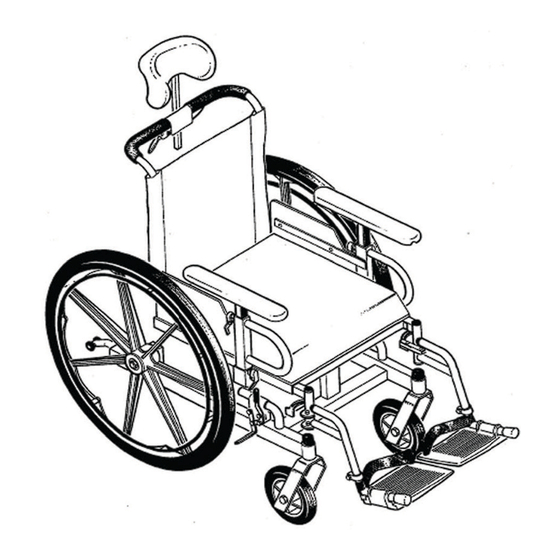
Page 26: Component Identification
3 OVERVIEW Component Identification Headrest Tilt-in-Space Release Lever Adjustable Armrest Anti-Tippers Swing Away Footrest Armrest Release Lever Flip Up Foot Plate Wheel Lock Footrest Release Lever Front Caster ® Invacare Concept 45 Wheelchair Part No. 1088191... -
Page 27: Specifications
Wheel Locks: Push or Pull to Lock Caster: 7 inch Composite Urethane Upholstery: Black Nylon (screw on) Weight Limit: 250 lbs Weight: 55 pounds (Aprox.)16 X 16 inch Seat, Without Front Riggings ® Part No. 1088191 Invacare Concept 45 Wheelchair... -
Page 28: Section 4-Safety Inspection/Troubleshooting
Inspect the back cane hand grips for wear/looseness/deterioration. ❑ Inspect seat positioning strap for any signs of wear. Ensure buckle latches. Verify hardware that attaches strap to frame is secure and undamaged. Replace if necessary. ® Invacare Concept 45 Wheelchair Part No. 1088191... - Page 29 Check that all labels are present and legible. Replace if necessary. ❑ Inspect the gas cylinders for leaking oil. Replace if necessary. ❑ Inspect the trigger release lever and cable to ensure proper release and engage the tilt-in-space lock. ® Part No. 1088191 Invacare Concept 45 Wheelchair...
- Page 30 Check headtube locknuts for tightness. Inspect/Adjust Periodically ❑ Inspect frame and crossbraces for loose or missing hardware. ❑ Inspect for bent frame or crossbraces. ❑ Check that wheel locks are easy to engage. ® Invacare Concept 45 Wheelchair Part No. 1088191...
-
Page 31: Troubleshooting
LOOSENESS SOLUTIONS RIGHT/LEFT OR PERFORMANCE FLUTTER RATTLES IN CHAIR Check tires for correct and equal pressure Check for loose nuts and bolts. Check that both casters contact ground at the same time. ® Part No. 1088191 Invacare Concept 45 Wheelchair... -
Page 32: Maintenance
As with any vehicle, check the wheels and tires periodically for cracks and wear. Replace as recommended. The rear wheels, casters and tires should be checked periodically for cracks and wear, and should be replaced by a qualified technician if damaged. ® Invacare Concept 45 Wheelchair Part No. 1088191... - Page 33 11. Periodically check gas cylinders for oil leaks. If oil leak is detected, replace the cylinder(s). Replacing/Repairing Rear Wheel Tire/Tube WARNING Replacement of solid urethane tires is not recommended. If the solid urethane tire needs repaired, Invacare recommends replacing the complete wheel assembly. Replacement of rear wheel tube must be performed by a qualified technician.
-
Page 34: Section 5-Front Riggings
Release Lever Removing Hinge Plates Push the front rigging release lever inward. Rotate swingaway front rigging assembly outward. Lift the swingaway front rigging assembly off the hinge pins. FIGURE 1 Installing/Removing Front Riggings ® Invacare Concept 45 Wheelchair Part No. 1088191... -
Page 35: Adjusting Footplate Height
Reinstall the front rigging. Refer to Installing/Removing Front Riggings on page 34 Repeat STEPS 1-5 to adjust the remaining footrest. Legrest Tube Footplate Assembly Swingaway footrest shown. Hex Head Screw and Locknut FIGURE 2 Adjusting Footplate Height ® Part No. 1088191 Invacare Concept 45 Wheelchair... -
Page 36: Raising/Lowering Elevating Legrest Assembly
Support user leg with one hand. Push release lever downward with other hand. FIGURE 4 Adjusting the Calfpad Gently, lower user leg down and rest against the legrest. Release Lever Support Tube FIGURE 3 Raising/Lowering Elevating Legrest Assembly ® Invacare Concept 45 Wheelchair Part No. 1088191... -
Page 37: Section 6-Arms
Adjust armrest to desired height. (Pull to Unlock Armrest) Release the armrest adjustment pin to lock the armrest at the desired height. FIGURE 1 Removing/Installing/Adjusting the Armrest Repeat STEPS 1-3 for other armrest. ® Part No. 1088191 Invacare Concept 45 Wheelchair... -
Page 38: Section 7-Seat And Back
The back MUST be locked securely in place before Lock using the wheelchair. FIGURE 1 Folding/Unfolding the Back Canes To fold the back, pick up on the release cord and push the back towards the front of the chair. ® Invacare Concept 45 Wheelchair Part No. 1088191... -
Page 39: Back Angle Adjustments
The necessary back angle MUST be selected BEFORE repositioning the rear wheels forward 90° and adjusting the limit stops. Invacare DOES NOT Mounting Holes 110° recommend adjusting the back angle after the rear wheels have been repositioned forward. If the rear... -
Page 40: Engaging The Tilt-In-Space System
Both gas cylinders MUST be operational before using the chair. DO NOT operate the tilt-in-space if only one (1) of the cylinders is operational. The Concept 45 wheelchair MUST be operated by an attendant when in any tilted position. Place the chair on a level surface. -
Page 41: Section 8-Rear Wheels
If necessary, repeat STEPS 1-2 for opposite rear wheel. Installing Install permanent axle through the rear wheel, axle bracket, washer and locknut. Securely tighten with the existing locknut. Torque to 20-40 ft-lbs. ® Part No. 1088191 Invacare Concept 45 Wheelchair... - Page 42 8 REAR WHEELS Reinstall the dust cap. If necessary, repeat STEPS 1-3 for opposite rear wheel. Locknut Permanent Axle Axle Bracket Wheelchair Dust Cap Frame Washer Rear Wheel FIGURE 1 Removing/Installing Rear Wheels ® Invacare Concept 45 Wheelchair Part No. 1088191...
-
Page 43: Repositioning The Rear Wheels
Repeat procedure for opposite axle mounting plate and anti-tipper bracket. WARNING The locking pins MUST BE protruding past the inside of the rear wheel mounting bracket. Both rear wheels MUST be in the same position on the chair frame. ® Part No. 1088191 Invacare Concept 45 Wheelchair... - Page 44 Repeat the above procedures until the wheelchair is stable. Adjust the wheel locks. Refer to Adjusting Patient Operated Wheel Locks on page 53. Adjusts Backward Adjusts Forward Axle Mounting Bracket Locknut Bolt Washers Wheelchair Frame FIGURE 2 Repositioning The Rear Wheels ® Invacare Concept 45 Wheelchair Part No. 1088191...
-
Page 45: Replacing Rear Wheel Handrim
Secure the new handrim to the rear wheel with mounting screws. Tighten securely. Reinstall rear wheel to the wheelchair. Refer to Removing/Installing Rear Wheels on page 41. FIGURE 3 Replacing Rear Wheel Handrim ® Part No. 1088191 Invacare Concept 45 Wheelchair... -
Page 46: Section 9-Front Casters
Slide the new fork assembly into the caster headtube. Reassemble by reversing STEPS 1-3. Repeat STEPS 1-6 for the opposite fork assembly. Adjust the forks. Refer to Adjusting Forks on page 47. FIGURE 1 Installing/Replacing Five/Eight Inch Front Casters/Forks ® Invacare Concept 45 Wheelchair Part No. 1088191... -
Page 47: Adjusting Forks
Repeat STEPS C-D until wheels swing once to one-side, then IMMEDIATELY rest in a downward position. Test wheelchair for maneuverability. Readjust locknuts if necessary, and repeat STEPS 1-2 until correct. Snap dust cover over the locknut and stem. ® Part No. 1088191 Invacare Concept 45 Wheelchair... -
Page 48: Replacing Front Casters
Remove the hex screw, locknut and the two washers and spacers that secure the front caster to the fork. Front Caster Spacer Washer To reinstall the new front caster onto the fork, reverse STEP 1. FIGURE 2 Replacing Front Casters ® Invacare Concept 45 Wheelchair Part No. 1088191... -
Page 49: Section 10-Anti-Tippers/Wheel Locks
If ground clearance cannot be achieved, DO NOT use the wheelchair. Contact a qualified technician. Invacare strongly recommends that anti-tippers be used at all times. Anti-tippers MUST be fully engaged and release buttons fully protruding out of the adjustment holes. - Page 50 FIGURE 1 Installing Anti-Tippers If the distance between the bottom of anti-tipper wheels and the -1/2 ground/floor is not 1 to 2 inches, adjust anti-tippers. Refer to Adjusting the Anti-Tippers on page 51. ® Invacare Concept 45 Wheelchair Part No. 1088191...
- Page 51 Using the locking screw, secure the wheeled portion of the Locking Screw anti-tipper to the anti-tipper tube. Repeat STEPS 2-4 to adjust the remaining anti-tipper. FIGURE 2 Adjusting the Anti-Tippers Ensure both anti-tippers are adjusted to the same height. ® Part No. 1088191 Invacare Concept 45 Wheelchair...
-
Page 52: Using/Adjusting Patient Operated Wheel Locks
Unlocked Position Wheel Lock Unlocked Position Wheel Lock Locked Position Locked Position FIGURE 3 Using Patient Operated Wheel Locks ® Invacare Concept 45 Wheelchair Part No. 1088191... -
Page 53: Adjusting Patient Operated Wheel Locks
Repeat STEPS 1-7 for the opposite wheel lock. Wheel Engage both wheel locks and ensure the occupied wheelchair is held Wheel Lock Shoe in place when pushed. FIGURE 4 Using Patient Operated Wheel Locks ® Part No. 1088191 Invacare Concept 45 Wheelchair... -
Page 54: Section 11-Seat To Floor
Front Casters on page 46. Reinstall the rear wheels onto the wheelchair in the mounting position indicated in the chart. Refer to Removing/Installing Rear Wheels on page 41. ® Invacare Concept 45 Wheelchair Part No. 1088191... - Page 55 22 inch BOTTOM 5 inch MIDDLE 17 1/2 22 inch BOTTOM 7 inch FIGURE 1 Changing Seat-to-Floor Height 18 1/4 24 inch BOTTOM 8 inch 18 1/4 24 inch BOTTOM 5 inch MIDDLE ® Part No. 1088191 Invacare Concept 45 Wheelchair...
-
Page 56: Section 12-Options
ALWAYS wear your positioning strap. Inasmuch as the Seat Positioning Strap is an option on this wheelchair (You may order with or without the seat restraint), Invacare strongly recommends ordering the Seat Positioning Strap as an additional safeguard for the wheelchair user. -
Page 57: Installing The Wheel Lock Extension Handle
Install the extension handle over the wheel lock handle (Detail “B”). Detail “B” Detail “A” Wheel Lock Rubber Tip Extension Handle Wheel Lock Handle Wheel Lock Handle Wheel Lock Wheel Lock FIGURE 2 Installing the Wheel Lock Extension Handle ® Part No. 1088191 Invacare Concept 45 Wheelchair... - Page 58 NOTES NOTES ® Invacare Concept 45 Wheelchair Part No. 1088191...
- Page 59 NOTES NOTES ® Part No. 1088191 Invacare Concept 45 Wheelchair...
- Page 60 Invacare Corporation Canada INVAMEX S.DE R.L. DE C.V. One Invacare Way 570 Matheson Blvd E Avenida Industrial el Puente s/n Elyria, Ohio USA Unit 8 Parque Industrial el Puente 44035 Mississauga Ontario Manimex 800-333-6900 L4Z 4G4 Canada Reynosa, Tamaulipas MEXICO 800-668-5324 C.P.
Need help?
Do you have a question about the Concept 45 and is the answer not in the manual?
Questions and answers