Advertisement
Table of Contents
*P516-958*
P516-958
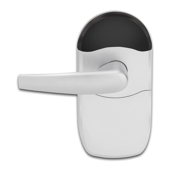
Model NDE80
Key
Outside Lever
Cylinder
Strike
Strike Options
ANSI Strike
Installation Preparation
Tools Needed
• Phillips screwdriver
• Pin wrench
• Pencil
Optional
• T-15 Tamper Torx screwdriver
IMPORTANT NOTES
Magnet tray and included strike MUST be installed!
The magnet is used to indicate door position.
Door position MUST be calibrated using the application.
Install and test lock with door open to avoid being locked out.
MOBILE APPLICATION
Search for "Schlage Engage" in the
Apple App Store or Google Play Store to
download.
Navigate to the website to set up your
online account.
NDE Wireless Lock
Outside Assembly
Chassis
Latch
Backplate
T-Strike
Door preparation:
For door preparation
instructions, see included
instructions or contact
Technical Service at
1-877-671-7011.
Ribbon Cable
Spring Cage
Mounting
Screws
Battery Strap
A
Install latch.
The bevel must face toward the door stop.
Installation Instructions and User Guide
Pin wrench
Inside
Assembly
Escutcheon
Screws
Battery Cover
Battery Holder
Actual Size
Cylinder Options
Full Size IC (FSIC)
Small Format (SFIC)
Standard Cylinder
Inside Lever
Battery Cover
Screw
Advertisement
Table of Contents

Related Manuals for Schlage NDE80


Summary of Contents for Schlage NDE80
- Page 1 Door position MUST be calibrated using the application. Install and test lock with door open to avoid being locked out. MOBILE APPLICATION Actual Size Search for “Schlage Engage” in the Apple App Store or Google Play Store to download. Navigate to the website to set up your...
- Page 2 Door Thickness Adjustment Install strike and magnet tray assembly. For 1B\,” or 2” thick doors, complete the following door thickness Note: If dustbox is included, install first. adjustment steps. CAUTION L For 1C\v” thick doors, NO ADJUSTMENT IS REQUIRED. Continue to step 3. Magnet tray and included strike must be installed! DO NOT DISCARD! Remove chassis from outside assembly.
- Page 3 Reinstall adjustment plate. To change handing, pull lever post until it stops, then Tighten until door thickness insert enters notch in adjustment plate. rotate 180 degrees. Align lever catch pin and slide hole to latch side. Release lever post. Assembly will click into place. CAUTION Do not route ribbon cable before rotating chassis! Lever Catch Pin...
- Page 4 Align assembly and install on door. Install spring cage. Let the wire hang on the other side, through the hole. Align lever catch pin to door edge. WARNING Do not pinch ribbon cable! WARNING Ensure that the lever catch pin is aligned with latch side before continuing! Lever Catch Pin Actual Size...
-
Page 5: Install Batteries
Install Batteries Install battery cover screw. Choose either standard Phillips screw or Torx screw. Install batteries into battery holder. Push the tab on the right of the battery securing band, and pull out to release battery holder. Connect cable from battery holder to connector on circuit board. - Page 6 Lever Removal Lever With Interchangeable Core Cylinder Install cylinder tailpiece. Rotate cam in lever post until the cam stops. To remove a lever with a To remove a lever without a cylinder, insert key first, and cylinder, press pin wrench into turn it 90 degrees toward door hole in lever, and pull off.
-
Page 7: Need Help
Master Programming Credential will not grant access. It is used only to add additional credentials. 1. Download the mobile application. Search for “Schlage Engage” in the App Store. L Use the same Master Programming Credential for all the locks in the facility. -
Page 8: Troubleshooting
FDR mode. the expected lock Mode before BLE • Install the battery If you have used this NDE in Construction Access Mode, you must name, or “Schlage will work. cover. Lock”. • The tamper switch • Turn the outside lever, complete a FDR before it will communicate on BLE. -
Page 9: Fcc Statement
FCC Statement Possible Problem Action This equipment has been tested and found to comply with the limits for a Class B digital Cause device, pursuant to Part 15 of the FCC Rules. These limits are designed to provide reasonable protection against harmful interference in a residential installation. This Intermittent Wi-Fi •...
Need help?
Do you have a question about the NDE80 and is the answer not in the manual?
Questions and answers