Table of Contents
Advertisement
Quick Links
Advertisement
Table of Contents

Related Manuals for PCE Instruments PCE-USC 30


Summary of Contents for PCE Instruments PCE-USC 30
- Page 1 User Manual PCE-USC 30 User manuals in various languages (Deutsch, français, italiano, español, português, nederlands, türk, polski, русский, 中文) can be downloaded here: www.pce-instruments.com Last change: 6 January 2017 v1.0 © PCE Instruments...
-
Page 2: Table Of Contents
Labelling is made on the flaw detector casing by polygraphic technique......52 Pattern approval mark is made on the flaw detector electronic unit by at least two seals made on screws of casing cover....................52 Composition and Delivery Set ............53 © PCE Instruments... - Page 3 10.1 The list of the most common and probable failures is given in Table 9......58 Table 9 – Typical failures and troubleshooting ................58 11 Transportation and Storage ............... 58 12 Warranty ....................58 13 Disposal ....................59 © PCE Instruments...
-
Page 5: Safety Notes
Thank you for purchasing a PCE-USC 30 from PCE Instruments. Safety notes Please read this manual carefully and completely before you use the device for the first time. The device may only be used by qualified personnel and repaired by PCE Instruments personnel. Damage or injuries caused by non- observance of the manual are excluded from our liability and not covered by our warranty. -
Page 6: Specifications
We expressly point to our general guarantee terms which can be found in our general terms of business. If you have any questions, please, contact PCE Instruments. The contact details can be found at the end of this manual. Safety symbols Safety-related instructions the non-observance of which can cause damage to the device or personal injury carry a safety symbol. - Page 7 Weight of the flaw detector with a storage battery (without ECP set, cables and casing) – no more than 0.9 kg. Overall dimensions of the flaw detector – no more than 230 mm x 135 mm x 98 mm. © PCE Instruments...
-
Page 8: System Description
System description Device User manual of PCE-USC 30 portable eddy current flaw detector (hereinafter referred to as "Flaw detector"), is intended for the study of operation principles of the flaw detector and its operating instructions, and includes the information on application, specifications, operating principle and structure, operating instruction, and also other information allowing a full-scale implementation of flaw detector technical capabilities. -
Page 9: Display And Side Panels
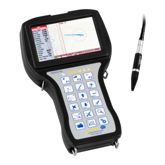
1 – Ethernet port for connecting a communication cable to PC; 2 – USB port for updating the flaw detector software and recording the testing results on the external Flash-Card Fig. 1 – PCE-USC 30 Rear Panel © PCE Instruments... - Page 10 Data of receiver «+» Data of receiver «–» ERA.0S.304.CLL (front view) Table 2 – Description of connector for the instrument connection to the PC USB port Contact Signal type (front view) +5 V Data - Data + Common © PCE Instruments...
- Page 11 Front Panel Fig. 2 – PCE-USC 30 Front Panel © PCE Instruments...
- Page 12 1 - LEMO jack for headphones with microphone connection; 2 - Charger connector; 3 - Switching On/Off the instrument. Fig. 3 – PCE-USC 30 Left Side Panel Table 3 – Description of LEMO jack for headphones with microphone connection Cont.
- Page 13 Right side panel of the flaw detector: 1 – Single coil (parametric) eddy current probe (ECP) connector; 2 - Universal connector for eddy current probe (ECP) and eddy current rotary scanner; 3 - Encoder (Enc) connector Fig. 4 – PCE-USC 30 Right Side © PCE Instruments...
- Page 14 Table 6 – description of encoder (Enc) connector Cont. Signal Lemo EGG.1B.308CLL Positive signal input "A" (front view) Power "+5V" Negative signal input "Z" Positive signal input "Z" Negative signal input "B" Positive signal input "B" Negative signal input "A" Common © PCE Instruments...
-
Page 15: Function Keys
"F1 Import data", "F2 Export data "– in “MEMORY” menu; "F1 Load", "F2 Create/ Save","F3 Delete"– in "RESULTS"/"SETTINGS" submenu; "F1 An" (An - amplitude noise) – in "VIEW" menu; "F2 OK” save calibration curve – in "CALIBRATION" menu. © PCE Instruments... - Page 16 - pressing the key in "TEST" menu results in saving of current setup as a default one (if the current item is above the ALARM item); - add point in “CALIBRATION" menu - quick access to "TEST" menu - quick access to "SETTINGS" menu © PCE Instruments...
- Page 17 - quick access to "CALIBRATION" menu - automatically sets the parameters of single coil (parametric) ECP with switched On Single input; - sets the number of rounds while operating with eddy current rotary scanner - switches On/Off the instrument © PCE Instruments...
-
Page 18: Design Of The Flaw Detector
Design of the Flaw Detector Instrument Appearance Fig. PCE-USC 30 eddy current flaw detector © PCE Instruments... -
Page 19: Structural Scheme
ALARM and overloading, Ethernet port for connection to PC, USB port for external flash-card connection, charger connector, headphones and microphone; b) connector, ECP connector; c) TFT display; d) processor and memory boards; e) analog board; f) battery. © PCE Instruments... -
Page 20: Appearance Of The Flaw Detector Screen
FREQ – test frequency; PRE AMP – preamplifier gain; GAIN – main gain; H GAIN – horizontal gain; V GAIN – vertical gain; DRIVE – probe drive level; PHASE – phase adjustment; FILTER – filter type; POSITION – spot position; © PCE Instruments... - Page 21 1 – Navigation menu 2 – Time charts 3 – ALARM frame 4 – Eddy current signal 5 - Signal display area © PCE Instruments...
- Page 22 Lighting of a left overload indicator (pos. 10, Fig. 8) – indicates that unacceptably large amplitude signal came to the input of the receiving circuit. The flaw detector electronic unit displays the signal in the complex plane that allows to foil defects by waveform analysis (Fig. 9): © PCE Instruments...
- Page 23 ALARM for each frequency and mix. ALARM itself is the response of flaw detector to the event occurring at crossing or non-crossing of alarm frame (threshold level) by a signal. All in all one alarm frame can be activated for each frequency. © PCE Instruments...
- Page 24 (see Fig. 11): differential ECP, connection by the bridge circuit; single transformer ECP; differential ECP, connection by the bridge circuit; differential transformer ECP with center-point ground; single (parametric) ECP; differential transformer ECP. © PCE Instruments...
-
Page 25: Menu Structure
Fig.11 – Circuits of probe connection Menu Structure Fig. 12 – Menu Structure © PCE Instruments... -
Page 26: Test" Menu
ALARM and general flaw detector parameters. © PCE Instruments... - Page 27 Moving through the vertical menu of the electronic unit parameters is carried out by keys. In order to change the value of any parameter one should use keys. A step of parameter variations can be changed by multiple pressing of key. © PCE Instruments...
- Page 28 If the flaw detector was once balanced and its operating frequencies were not changed, it is possible to carry out centring. Operating frequency of probe is selected from the rage of frequencies indicated in the registration certificate for the given ECP. © PCE Instruments...
- Page 29 PHASE" - signal phase change (signal turn) – from 0 to 360˚ 7. " with a step of 0.1˚, 1˚, 10˚. ECP exciting voltage is selected from the range indicated in the registration certificate for the given ECP. © PCE Instruments...
- Page 30 Since differential probes generate a dual signal that changes more quickly than that of an absolute probe at the same speed, you © PCE Instruments...
- Page 31 Bandpass Switching on of a bandpass filter activates its settings: Carrier frequency F is set from 1 to 5000 Hz with a step of 1; 10; 100; 1000 Hz; © PCE Instruments...
- Page 32 17. "Mix type" – is selected for the frequencies mixing (setting is available in double frequency mode), where: "+" – summation, "–" – subtraction, "~X+" - summation with inversion in Х-direction, "~Y+" - summation with inversion in Y-direction. © PCE Instruments...
- Page 33 Threshold levels setup Setup of "Circle" type frame To set up circle type frame, operator should select "Type: " in special item of settings ALARM – (see Figure 14). Fig. 14 – Setup of “Type: “ threshold level © PCE Instruments...
- Page 34 Parameter variation is carried out in the range from 0 to 32768 with a step of 1, 10, 100, 1000, 10000 (see Fig. 15). Setup of "Sector" type frame To set up sector type frame, operator should select "Type: " in special item of settings ALARM – (see Figure 16). © PCE Instruments...
- Page 35 – the signal gets beyond the limits of the threshold level; – the signal is within the limits of the threshold level. If the symmetrical displaying of threshold level on the position “Symm:” with keys is required, this parameter can be activated. © PCE Instruments...
- Page 36 - 32768 with a step of 1; 10; 100; 1000; 10000 (see Fig. 17). Select the frame polarity "Pol:", which makes the alarm trigger: – the signal gets beyond the limits of the threshold level – the signal is within the limits of the threshold level. © PCE Instruments...
-
Page 37: Guidelines For Overload Processing
If the left indicator lights, then repeat the steps described for overload processing for the left indicator (see above); If the right indicator lights only, then it is required alternately reduce the “ 4.6.3.2 AMP” and “ GAIN”. After each gain change it is required to press key. © PCE Instruments... -
Page 38: Conductivity" Mode
Conductivities of metals at ambient temperature are typically in the range of 1 to 60 MegaSiemens per meter. The PCE-USC 30 measures the conductivity of non-magnetic metals and alloys in the range 0.8 to 110.0 % IACS. It uses the Eddy Current technique for measuring the conductivity of materials in % IACS, or MSiemens/meter. - Page 39 «CP13 – 480 kHz». Fig. 19 – Choosing and activating Settings “CP 13 – 60 KHZ” After settings activation make calibration at standard samples Note – For setting up procedure, use certified calibration blocks only. © PCE Instruments...
- Page 40 Set the eddy current probe on the sample with Cond 1 conductivity and press Figure 20 – Entering the conductivity value for the sample Cond 1 Set the eddy current probe on the sample with Cond 2 conductivity and press © PCE Instruments...
- Page 41 Note. In case, the ambient and test object temperature will be different from 20 ˚С (68˚ F), then the displayed value will be with an error. © PCE Instruments...
-
Page 42: General Settings" Menu
ALARM shall be triggered, when the measured value of electric conductivity gets beyond the selected range Min – Max. Measuring Conductivity and Coating Thickness with the PCE-USC 30 Guidelines for successful operation: For accurate measurement of conductivity, the surface coating thickness should be 0.5 mm (0.020 inches). - Page 43 - "Date" – selection of current date (year, month, date); - "Time" – selection of current time (hours, minutes, seconds) 4 Cenc value (pulses/mm) is indicated in the registration certificate for the scanning device where an encoder (Enc) is used © PCE Instruments...
-
Page 44: View
The values of amplitude in volts, phase in degrees and defect depth in millimetres or percent are displayed in the information line. © PCE Instruments... -
Page 45: Memory" Menu
"RESULTS" or "SETTINGS" and press key. The flaw detector is capable of storing of more than 1000 settings and up to 1000 testing results (depending on the defectogram size) in the memory. Fig. 20 – "RESULTS" menu © PCE Instruments... -
Page 46: Results" Menu
With the help of function keys "F3 Delete" (see Figure 27) – an operator can load the selected result (settings and data are automatically loaded), save the current result and delete the selected result. Fig. 27 - Operations with the testing results © PCE Instruments... -
Page 47: Settings" Menu
Figure 29). The signals from the defect are not bound to stay only within the limits of one screen scan. When operating with MDF probes, the mark on ECP case must coincide with the direction of scanning trajectory. © PCE Instruments... - Page 48 4 - Calibration block selection 5 - Position of the measuring cursor on the time chart; 6 - Width of the measuring cursor on the time chart; 7 - The type of the measuring cursor, see item 3.9 © PCE Instruments...
- Page 49 (see Fig. 31). Then it is essential to perform similar operations for all other defects by setting corresponding depth. Fig. 31 – Plotting of the calibration curve © PCE Instruments...
-
Page 50: Communication With Pc
4.14 Communication with PC The flaw detector in a set with "PCE-USC 30" software ensures communication mode with a PC for the information input to the PC from the flaw detector memory (testing results, operating setups) and the possibility to print out this information and to form a report. - Page 51 (by default the "RESULTS" folder is proposed, saved on the hard disk drive of PC in the program directory of «PCE-USC 30»). This file can be located in the flaw detector memory or also be stored on hard disk drive of PC (if previously copied to the hard disk drive (4.14.3.2)).
- Page 52 Fig. 35 – “Selecting the interface language” window Note – Reload the program to change the interface language. Select "Exit" subitem to finish the "PCE-USC 30" program. When selecting "Report" item of the main menu, there appears a window for filling in the report form of the testing carried out (Fig.
- Page 53 - Cnt-Pk (centre peak - the measurements is made between the cursor centre and the point situated at the max. distance from the centre in cursor width); - Cnt-K (centre cursor - the measurements is made between the centre and the cross point of cursor centre signal); © PCE Instruments...
- Page 54 - scaling down the signal image - restoring the initial horizontal to vertical ratio. Scale (H) – allows to adjust the horizontal scaling of a signal image: - scaling-up the signal image horizontally; - scaling down the signal image horizontally; © PCE Instruments...
- Page 55 To save the testing results from the flaw detector memory to PC, connect the flaw detector to PC using a USB cable (item 4.14.3.1). In the menu of «PCE-USC 30» program select the item "Loading", and after, in the program window there are displayed the files of all the testing results stored in the flaw detector memory.
-
Page 56: Labelling And Sealing
4.14.3.3 Viewing results of testing Download «PCE-USC 30» program to PC. In "File" item of the main menu choose the sub-item "Open". In the window that appears, choose the path to removable media – the flaw detector memory or the path where previously there was stored data on PC, move the cursor to the necessary file with the testing results and click "Open". -
Page 57: Composition And Delivery Set
Composition and Delivery Set Basic delivery set consists of the following components: Table 8 Name and reference designation Quantity PCE-USC 30 electronic unit SS340K09DA0 eddy current probe in protective case Connection cable (Electronic unit/ECP) Connection cable (PC/electronic unit) Automatic charger Mascot Calibration block SOP 2353.08 (Rz 40, D16T) -
Page 58: Instructions For Use
6 It is recommended, the signal from the defect to be placed in the first or second quadrant of the complex plane. To correct the ECP phase use parameter. 7 Increasing the gain on preamplifier and amplifier you should maximize the signal amplitude, but at the same monitor behind parameters of the input circuit. © PCE Instruments... -
Page 59: Rotation Probe
After the ALARM was properly set up, the light alarm will be triggered on the flaw detector keypad at detecting the defect (digital indicators on the display) and sound alarm (if it has not been turned off in "SETTINGS" menu). © PCE Instruments... -
Page 60: Maintenance
The maintenance inspection includes an external examination and is performed by attending personnel before starting the flaw detector electronic unit operation. Replacement of the battery pack. 9.4.1 Unscrew two screws (item 1 Fig. 39). Fig. 39 © PCE Instruments... - Page 61 Open the contact terminal (item 1 Figure 40), pressing the clip (item 2 Figure 40). Fig. 40 9.4.3 Remove the battery pack (item 1 Figure 41). Fig. 41 9.4.4 Battery pack mounting is carried out strictly in reverse order. © PCE Instruments...
-
Page 62: Typical Failures And Troubleshooting
Evaluation of stability of the flaw detector and ECP performance under the effect of electromagnetic interferences should correspond to "B" criterion according to GOST 29073. Warranty You can read our warranty terms in our General Business Terms which you can find here: https://www.pce-instruments.com/english/terms. © PCE Instruments... -
Page 63: Disposal
For countries outside the EU, batteries and devices should be disposed of in accordance with your local waste regulations. If you have any questions, please contact PCE Instruments. APPENDIX A Requirements to Charging Device for Portable Eddy Current Flaw... - Page 64 Lemo FGG.1B.304.CLАD42 Component side view Front “-“ Charging device “+” Charging device Fig. A.1 – Soldering pattern of charging device output cable for the flaw detector connection © PCE Instruments...
- Page 65 PCE Instruments contact information Germany France Spain PCE Deutschland GmbH PCE Instruments France EURL PCE Ibérica S.L. Im Langel 4 76, Rue de la Plaine des Bouchers Calle Mayor, 53 D-59872 Meschede 67100 Strasbourg 02500 Tobarra (Albacete) Deutschland France España Tel.: +49 (0) 2903 976 99 0...
- Page 66 User manuals in various languages (German, French, Italian, Spanish, Portuguese, Dutch, Turkish, Polish, Russian, Chinese) can be downloaded here: www.pce-instruments.com Specifications are subject to change without notice. © PCE Instruments...
Need help?
Do you have a question about the PCE-USC 30 and is the answer not in the manual?
Questions and answers