Advertisement
Quick Links
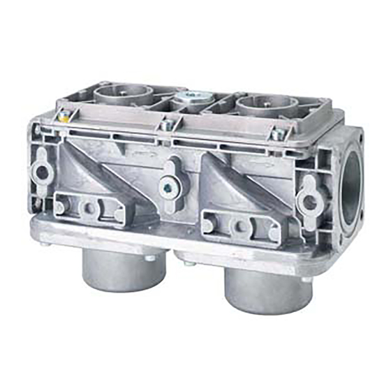
VGD Series
VGDxx.xxxU Gas Valves
for use with SKPxx.xxxU electro‐hydraulic actuators
VGD20.xxxU
ISO 9001 and 14000
REGISTERED FIRM
Description
Only with series SKPxx.xxxUx actuators
The normally closed VGDxx.xxxU series of modular double‐body gas valves combine
with SKPxx.xxxU series electro‐hydraulic actuators to provide safety shut‐off, gas
pressure regulation and/or air‐gas ratio control for commercial or industrial gas
burners.
Table 1. VGDxx.xxxU model numbers
Model Numbers
VGD20.253U
VGD20.323U
VGD20.403U
VGD20.503U
VGD40.065U
VGD40.080U
VGD40.100U
VGD40.150U
Technical Instructions
Body style
Double
Double
Double
Double
Double
Double
Double
Double
Document No. 7631
VGDxx.xxxU
November 08, 2017
VGD40.xxxU
Connection
NPT thread
NPT thread
NPT thread
NPT thread
NPT thread
NPT thread
ANSI flange
ANSI flange
Siemens AG Building Technologies Division
Advertisement


Need help?
Do you have a question about the VGD20.253U and is the answer not in the manual?
Questions and answers