Dell Edge Gateway 3001 Installation And Operation Manual
Hide thumbs
Also See for Edge Gateway 3001:
- Installation and operation manual (99 pages) ,
- Getting started manual (28 pages) ,
- Installation and operation manual (73 pages)

Related Manuals for Dell Edge Gateway 3001


Summary of Contents for Dell Edge Gateway 3001
-
Page 1: Installation And Operation Manual
Dell Edge Gateway 3001 Installation and Operation Manual Regulatory Model: N03G Regulatory Type: N03G001... - Page 2 WARNING: A WARNING indicates a potential for property damage, personal injury, or death. Copyright © 2016 Dell Inc. or its subsidiaries. All rights reserved. Dell, EMC, and other trademarks are trademarks of Dell Inc. or its subsidiaries. Other trademarks may be trademarks of their respective owners.
-
Page 3: Table Of Contents
Contents 1 Overview............................2 System views..........................................................Top view ................................Bottom view ................................... Left view ................................. Right view 3 Installing your Edge Gateway............................................. 10 Professional installation instructions ......................11 Instructions d'installation professionnelles ................Federal Communication Commission interference statement ............................ Industry Canada statement .......................... - Page 4 ..........................Flashing a new OS Image ..............................Flashing the BIOS ........................54 Edge Gateway CAN Module Functions 5 References..........................56 6 Contacting Dell.........................
-
Page 5: Overview
Overview The Edge Gateway 3000 Series is an Internet of Things device. It is mounted at the edge of a network, enabling you to collect, secure, analyze, and act on data from multiple devices and sensors. It enables you to connect with devices used in transportation, building automation, manufacturing, and other applications. -
Page 6: System Views
System views Top view Table 1. Top view Features Wireless LAN/Bluetooth/GPS port Connect the antenna to increase the range and strength of wireless/bluetooth/satellite signals. Mobile broadband antenna port one (3G/LTE) Connect a mobile broadband antenna to increase the range and strength of mobile broadband signals. ZigBee antenna port Connect a ZigBee antenna for intermittent data transmissions from a ZigBee-compliant sensor or input... -
Page 7: Bottom View
Table 2. Bottom view Features Service Tag label The Service Tag is a unique alphanumeric identifier that allows Dell Service technicians to identify the hardware components in your Edge Gateway and access warranty information. Earth A large conductor attached to one side of the power supply, which serves as the common return path for current from many different components in the circuit. - Page 8 Features NOTE: A intrusion event is triggered by a third-party enclosure to the Edge Gateway through a sensor. The sensor should have a cable, which is compatible with the intrusion switch connector on the Edge Gateway. Power/Ignition port Connect a 12-57V DC power cable for supplying power to the Edge Gateway.
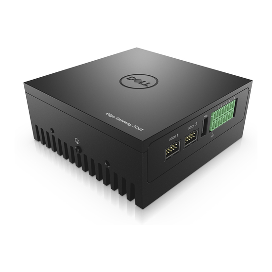
- Page 9 Right view Table 5. Right view — 3001 Features RS232/RS422/RS485 port one (configurable in the BIOS) Provides data transfer speeds up to 1 Mbps in RS232 and 12 Mbps in RS422/RS485. RS232/RS422/RS485 port two (configurable in the BIOS) Provides data transfer speeds up to 1 Mbps in RS-232 and 12 Mbps in RS422/RS485.
-
Page 10: Right View
Right view Table 5. Right view — 3002 Features CANbus port Enables the CANbus connection USB 2.0 port Connect a USB enabled device. Provides data transfer speeds up to 480 Mbps. Ethernet port two (Non-Poe) Connect an Ethernet (RJ45) cable for network access. Provides data transfer speeds up to 10/100 Mbps. -
Page 11: Installing Your Edge Gateway
WARNING: Before you begin any of the procedures in this section, read the safety information that shipped with your system. For additional best practices information, go to www.dell.com/regulatory_compliance. WARNING: The Edge Gateway is to be installed by knowledgeable, skilled persons familiar with local codes and regulations. -
Page 12: Instructions D'installation Professionnelles
Installation location The product shall be installed at a location where the radiating antenna is kept 20 cm from nearby persons in its normal operation condition in order to meet regulatory RF exposure requirements. External antenna Use only approved antenna(s). Non-approved antenna(s) may produce spurious or excessive RF transmitting power which may lead to a violation of FCC/IC limits. -
Page 13: Industry Canada Statement
FCC caution: · Any changes or modifications not expressly approved by the party responsible for compliance could void the user's authority to operate this equipment. · This transmitter must not be co-located or operating in conjunction with any other antenna or transmitter. Radiation exposure statement: This equipment complies with FCC radiation exposure limits for an uncontrolled environment. - Page 14 · Standard mount · DIN rail mount · Quick mount · Perpendicular mount · Cable control bar · VESA mount NOTE: Edge Gateway mounting options are sold separately. Connect an Ethernet cable (optional). Install the antenna(s) depending on the configuration ordered.
- Page 15 The antenna(s) supported in the Edge Gateway vary depending on the configuration ordered. Table 7. Antennas supported in Edge Gateway 3000 Series Antennas supported Signals 3000 Not applicable Not applicable 3001 Not applicable 3002 3003 Not applicable NOTE: Some of the antenna ports may be capped, depending on the configuration ordered.
- Page 16 NOTE: Mobile broadband antenna port two is for LTE only. It does not support 3G. Connect a USB cable to connect a display, keyboard, and mouse. Connect all cables to the appropriate I/O ports on the Edge Gateway. Open the micro-SIM/micro-SD card access door. Insert a micro-SIM card into the top micro-SIM card slot and activate your mobile broadband.
- Page 17 Replace the screw and close the access door. 10. Connect a ground cable to the Edge Gateway. 11. Connect the Edge Gateway to one of the following power source. · DC-IN...
-
Page 18: Activating Your Mobile Broadband
· PoE 12. When setting up the Edge Gateway for the first time, complete the operating system setup. For more information, Setting up your operating system. NOTE: The Edge Gateway is shipped with Windows 10 Enterprise 2016 or Snappy Ubuntu Core Series 16 operating system. - Page 19 Replace the screw and close the micro-SIM card access door. Turn on your Edge Gateway. Connect to a mobile network. Windows operating system If the Edge Gateway is shipped with LTE Verizon (DW5815) WWAN or LTE AT&T (DW5815) card: Select the network icon from the taskbar and then click Cellular. Select your Mobile Broadband Carrier →...
-
Page 20: Mounting Your Edge Gateway
NOTE: If the command runs successfully, the message OK appears. Configure the Network Control Mode with the at#ncm command. Example: at#ncm=1,3. Activate the Packet Data Protocol with the at+cgact command. Example: at+cgact=1,3. To view the PDP Context Read Dynamic Parameters, that is, bearer_id, apn, ip_addr, subnet_mask, gw_addr, DNS_prim_addr, DNS_sec_addr, P-CSCF_prim_addr, and P-CSCF_sec_addr parameters, run the at +cgcontrdp command. - Page 21 Place the Edge Gateway against the wall, and align the holes in the standard-mount bracket with the holes on the wall. Screw holes on the bracket have a diameter of 3 mm (0.12 in).
- Page 22 Place the standard-mount bracket on the wall, and, using the holes above the screw holes on the bracket, mark the location to drill the four holes.
- Page 23 Drill four holes in the wall that correspond to the holes in the standard-mount bracket.
- Page 24 Insert and tighten four screws (not supplied) to secure the Edge Gateway to the wall. It is recommended to use M4x9 screws.
- Page 25 Secure the Edge Gateway to the wall.
-
Page 26: Mounting The Edge Gateway On A Din Rail Using The Din-Rail Bracket
Mounting the Edge Gateway on a DIN rail using the DIN-rail bracket NOTE: The DIN-rail bracket includes the screws that are required for securing the bracket to the Edge Gateway. Align the screw holes on the DIN-rail bracket with the screw holes at back of the Edge Gateway. Place the two M4x7 screws on the DIN-rail bracket and secure it to the Edge Gateway. - Page 27 Secure the DIN-rail mounting bracket to the Edge Gateway by using the two M4x7 screws provided. NOTE: Torque the screws at 8+/-0.5 kilograms-centimeter (17.64+/-1.1 pounds-inch) on the DIN-rail mounting bracket.
- Page 28 Place the Edge Gateway on the DIN rail at an angle, and then pull the Edge Gateway down to compress the springs at the top of the DIN-rail mounting bracket. Push the Edge Gateway towards the DIN-rail brackets to secure the lower clip of the bracket onto the DIN rail.
-
Page 29: Mounting The Edge Gateway Using The Quick-Mount Bracket
Mounting the Edge Gateway using the quick-mount bracket The quick-mount bracket is a combination of the standard-mount bracket and DIN-rail bracket. NOTE: The mounting brackets are shipped with only those screws that are required for securing the mounting brackets to the Edge Gateway. Place the standard-mount bracket on the wall, and, using the holes above the screw holes on the bracket, mark the location to drill the four holes. - Page 30 Drill four holes in the wall that correspond to the holes in the standard-mount bracket. Screw holes on the bracket have a diameter of 3 mm (0.12 in).
- Page 31 Secure the standard-mount bracket to the wall with four screws (not supplied). Screw holes on the bracket have a diameter of 4.5 mm (0.04 in)
- Page 32 Align the screw holes on the DIN-rail bracket with the screw holes at the back of the Edge Gateway. Place the two M4x7 screws on the DIN-rail bracket and secure it to the Edge Gateway.
- Page 33 Mount the Edge Gateway on the standard-mount bracket and secure the Edge Gateway to the standard mount by pressing the latch.
- Page 34 Place the Edge Gateway on the standard mount at an angle, and then pull the Edge Gateway down to compress the springs at the top of the DIN-rail bracket.
- Page 35 Push the Edge Gateway towards the DIN-rail brackets to secure it on the standard-mount bracket. Secure the Edge Gateway to the standard-mount bracket.
-
Page 36: Mounting The Edge Gateway Using The Perpendicular Mount
Mounting the Edge Gateway using the perpendicular mount NOTE: The perpendicular mount is designed for DIN-rail applications only. Align the screw holes on the perpendicular-mount bracket with the screw holes on the Edge Gateway. - Page 37 Tighten the four M4x7 screws to secure the Edge Gateway to the perpendicular-mount bracket. NOTE: Torque the screws at 8+/-0.5 kilograms-centimeter (17.64+/-1.1 pounds-inch).
- Page 38 Align the screw holes on the DIN-rail mount bracket with the screw holes on the perpendicular-mount bracket, and tighten the two screws. NOTE: Torque the screws at 8+/-0.5 kilograms-centimeter (17.64+/-1.1 pounds-inch).
- Page 39 Place the Edge Gateway on the DIN rail at an angle. Pull the Edge Gateway down to compress the springs on the DIN-rail mount brackets and push the Edge Gateway towards the DIN-rail brackets to secure the bottom of the bracket to the DIN rail.
- Page 40 Push the Edge Gateway towards the DIN-rail brackets to secure the lower clip of the bracket onto the DIN rail. Secure the Edge Gateway on the DIN rail.
-
Page 41: Attaching The Cable Control Bars To The Standard-Mount Bracket
Attaching the cable control bars to the standard-mount bracket Mount the Edge Gateway on the wall using the standard-mount bracket quick-mount bracket. Place the cable control bar on the mounting bracket and secure it to the notch. - Page 42 Align the screw holes on the cable control bar with the screw holes on the mounting bracket. Tighten the six M3 x 3.5 mm screws that secure the cable control bar to the mounting bracket. NOTE: Torque the screws at 5+/-0.5 kilograms-centimeter (11.02+/-1.1 pounds-inch).
- Page 43 Connect the cables to the Edge Gateway. Loop the cable lock (not supplied) to secure each cable to the cable control bar.
-
Page 44: Mounting The Edge Gateway Using A Vesa Mount
Mounting the Edge Gateway using a VESA mount The Edge Gateway can be mounted on a standard VESA mount (75 mm x 75 mm). NOTE: VESA mount option is sold separately. -
Page 46: Setting Up Your Operating System
Create a new user name and password with admin rights to secure the system. Delete the default profile. Windows 10 IOT Enterprise LTSB 2016 basic functions BIOS Update BIOS updates for the Edge Gateway can be downloaded from www.dell.com/support. The download includes an executable that may be ran from the local machine. -
Page 47: Snappy Ubuntu Core Series 16
Watchdog Timer The Watchdog Timer for Windows 10 IoT Enterprise LTSB 2016 is controlled through the BIOS setting. Enter the BIOS during boot by pressing F2. The Watchdog Timer is enabled and disabled under the BIOS setting Watchdog Timer. TPM Support Windows 10 IoT Enterprise LTSB 2016 supports TPM 2.0. -
Page 48: Updating Operating System And Applications
NOTE: The user name and password are both lowercase. For example; Ubuntu 16.04 localhost.localdomain tty1 localhost login: ubuntu Password: ubuntu Press Enter, the following text is displayed: Ubuntu 16.04 localhost.localdomain tty1 localhost login: ubuntu Password Last login: Mon Nov 2 16:47:43 UTC 2015 on tty1 Welcome to Ubuntu Core Series 16, a transactionally updated Ubuntu * See http://ubuntu.com/snappy... -
Page 49: Useful Commands
NOTE: Check if a newer version of the software is available. For more information on checking for updates, see Updating operating system and applications. Useful commands To access the built-in help, run the (plano)ubuntu@localhost:~$ snap --help command. To see the system attributes, run the (plano)ubuntu@localhost:~$ snap info command. To see a list of all the snaps that are currently installed, run the (plano)ubuntu@localhost:~$ snap list command. -
Page 50: Network Communication Interfaces
Got to line number 42 and change the first console-ttyS0 so that it points to ttyS6 console=ttyS6. Now the line in the file should look like this: 42 set cmdline="root=LABEL=$label ro init=/lib/systemd/systemd console=ttyS6 console=tty1 panic=-1" Save the file, and reboot the Edge Gateway. Upon reboot you will be able to see the Operating System boot process as well as you will be able to login to the gateway via the console screen that is using the serial port on the front of the Edge Gateway. - Page 51 Access the command line utility. (plano)ubuntu@localhost:~$ sudo ./apps/bin/bluetoothctl To see what Bluetooth devices are installed on the system under test run the [bluetoothclt]# list command. To view the status of the installed Bluetooth device, run the [bluetoothclt]# show command. If the installed Bluetooth device is not powered on, run the [bluetoothclt]# power on command. If the installed Bluetooth device is not discoverable, run the [bluetoothclt]# discoverable on command.
-
Page 52: Additional Communication Interfaces
The CANbus LEDs default state is OFF, and will only be ON when data is being transmitted. Ready to use software to control or manipulate the device is not available from Dell. The information listed below is provide by the device’s manufacturer. Dell does not have any specifications regarding the function of F/W design of... -
Page 53: Security
Security Trusted Platform Module (TPM) TPM is supported on the Dell Edge Gateway 3000 Series. This setting is configurable in the BIOS and manageable in the Watchdog Timer WDT is recommended to be default enabled to active the fail-safe circuitry, Snappy is a Watchdog Timer compatible OS provides capability to detect and recover system from malfunctions, the design reacts by itself when system hangs unexpected crash. -
Page 54: Restoring Snappy Ubuntu Core Series 16
Connect a keyboard, mouse, and monitor to the Edge Gateway, or connect to the Edge Gateway through a KVM session. Turn on the system. Press F12 when the Dell logo is displayed on the screen to enter the boot menu. Select Factory Restore from the boot menu. -
Page 55: Flashing The Bios
Insert the USB flash drive in one of the available USB ports on the Edge Gateway. Turn on the Edge Gateway. Press F12 when the Dell logo is displayed on the screen to enter the One-time boot screen. On the One-time boot screen, choose Flash the BIOS . - Page 56 Linux host. There are no native application software on the factory installed OS image to perform CAN protocol for this device. The CAN module presence on the Gateway can be identified by issuing “lsusb” command in the Linux prompt and looking for “Microchip Technology Inc., ”...
-
Page 57: References
· Dell Command | Monitor User's Guide · Dell Command | Update User's Guide · Dell Command | PowerShell Provider User's Guide Additionally, for more information on using Dell Data Protection | Encryption see the documentation for the software at www.dell.com/support/manuals. -
Page 58: Contacting Dell
Go to www.dell.com/contactdell. Verify your country or region in the drop-down list at the bottom of the page. Select the appropriate service or support link based on your requirement or choose the method of contacting Dell that is convenient for you.
Need help?
Do you have a question about the Edge Gateway 3001 and is the answer not in the manual?
Questions and answers