
Related Manuals for Extron electronics VNM Enterprise


Summary of Contents for Extron electronics VNM Enterprise
- Page 1 User Guide Streaming AV Products VNM Enterprise Controller VN-Matrix ® Enterprise Controller 68-1999-01 Rev. C 07 13...
- Page 2 Safety Instructions Chinese Simplified Safety Instructions • English (简体中文) 警告: 产品上的这个标志意在警告用户该产品机壳内有暴露的危险 WARNING: This symbol, , when used on the product, is intended to 电压, 有触电危险。 alert the user of the presence of uninsulated dangerous voltage within the product’s enclosure that may present a risk of electric shock. 注...
- Page 3 “ Guide ” on the Extron website. Copyright © 2013 Extron Electronics. All rights reserved. Trademarks All trademarks mentioned in this guide are the properties of their respective owners. The following registered trademarks , registered service marks...
- Page 4 Conventions Used in this Guide Notifications The following notifications are used in this guide: DANGER: A danger indicates a situation that will result in death or severe injury. WARNING: A warning indicates a situation that has the potential to result in death or severe injury.
-
Page 5: Table Of Contents
Controller List ........17 VNS 104 Software Decoder Configuration ..64 Configuring the VN-Matrix Devices ....18 Actions Menu Bar ......... 64 VNS 104 Decode Windows ......68 About the Switcher Page ........70 Hidden Devices ..........72 VNM Enterprise Controller • Contents... - Page 6 Serial Port (COM) Connection ..... 153 About the Source Format Editor ..... 127 Using the VNM Enterprise Controller About the Display Format Editor ..... 128 User Interface ..........153 HLI Command Tables ........154 HLI Responses ........... 154 VNM Enterprise Controller • Contents...
- Page 7 UL Guidelines for Rack Mounting ....173 Basic Rack Mounting ........174 Rack Mounting Using Rack Rails ....175 HLI Command Overview ......... 178 HLI Command Examples ........ 179 General Commands ........180 Preset Commands.......... 198 VNM Enterprise Controller • Contents...
- Page 8 VNM Enterprise Controller • Contents viii...
-
Page 9: Introduction
VN-Matrix 200 / 225 / 300 / 325 devices, VNM recorders, and VNS software decoders. The menus on the VNM Enterprise Controller contain configuration and control menus for these devices. Where necessary, differences in the configuration and operation of controls for a specific VN-Matrix model or series is identified. VNM Enterprise Controller • Introduction... -
Page 10: About The Vnm Enterprise Controller
However, for large systems (more than ten devices) the VNM Enterprise Controller provides a more sophisticated user interface that simplifies the configuration and usability of a VN-Matrix system. VNM Enterprise Controller • Introduction... -
Page 11: About Dual (Redundant) Vnm Enterprise Controllers
RGB/DVI OVER IP Cluster Port 192.168.254.253 LAN-1 LAN-2 STATUS VN-MATRIX 225 SERIES RGB/DVI OVER IP VNM Enterprise Controller (Secondary) Multiple VNM 200 and 225 Series Devices Browser Based User Control Figure 2. Dual (Redundant) VNM Enterprise Controller System VNM Enterprise Controller • Introduction... -
Page 12: Transport Protocols Used For Streaming
However, because RTP is a connectionless protocol, data delivery is not guaranteed. When data packets are lost (for example, due to excessive network traffic) the VN-Matrix 200 / 225 / 300 / 325 devices carefully manage the data stream to minimize image disruption. VNM Enterprise Controller • Introduction... -
Page 13: Unicast Rtp - An Overview
Figure 5. Unicast TCP Streaming specified encoder. The decoder defines which source it connects to. Other than defining an IP address and source type (if required), no special source encoder setup is required. VNM Enterprise Controller • Introduction... -
Page 14: Definitions
Supplies the network heartbeat for encoder and decoder synchronization and communication. • High-level interface provides single point of control for external control systems. • Manage multiple VN-Matrix systems in combined or independent domains. • Provides redundant control in mission critical applications. VNM Enterprise Controller • Introduction... -
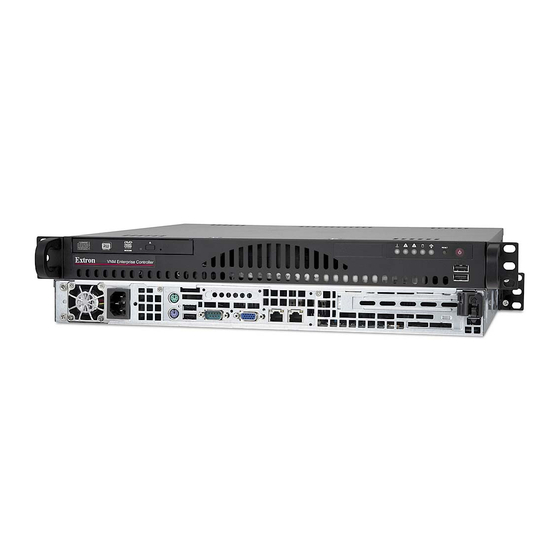
Page 15: Panels And Cabling
VN‑Matrix Product Variants on page 161. Do not remove the compact flash drive when the ATTENTION: VNM Enterprise Controller is powered on. Power down the controller before removing the compact flash drive. VNM Enterprise Controller • Panels and Cabling... - Page 16 When the main power is turned off, standby power is actively supplied to the controller. USB (Universal Serial Bus) ports — Insert any compatible USB device into these ports. The ports are not required for normal operation. VNM Enterprise Controller • Panels and Cabling...
-
Page 17: Rear Panel Features
Ethernet connector (eth1) — Connect an RJ-45 cable to this port. This port connects to a second VNM Enterprise Controller and is used to monitor the status of the primary VNM Enterprise Controller in a redundant configuration. This port is also referred to as the "cluster" or "service" port. VNM Enterprise Controller • Panels and Cabling... -
Page 18: Controller Configuration And Operation
Update the firmware of connected VN-Matrix devices. • Record and play back video using a connected VN-Matrix recorder. • Create and save presets to quickly reconfigure devices. • Stream to desktops with VN-Matrix software decoders. VNM Enterprise Controller • Controller Configuration and Operation... -
Page 19: Accessing The Web-Based User Interface
Administrator — This profile allows full access to all of the web-based user interface configuration settings and is the default configuration profile. Administrator username — Default: admin • Administrator password — By default, no password is required. • VNM Enterprise Controller • Controller Configuration and Operation... -
Page 20: Power Down Procedure
Front Panel Features on page 7). The power LED turns off. NOTE: Turning off the controller using the power button removes the main power, but standby power is still supplied to the system. VNM Enterprise Controller • Controller Configuration and Operation... -
Page 21: Single Enterprise Controller Configuration
Firmware and License Updates on page 155). Power down the VNM Enterprise Controller (see Power Down Procedure on page 12) and all configured devices. After a few seconds, power on the VNM Enterprise Controller and all necessary devices. VNM Enterprise Controller • Single Enterprise Controller Configuration... -
Page 22: Single Vnm Enterprise Controller Settings Configuration
Make sure the VNM Enterprise Controller is not "paired". If it is paired, the unit must first be unpaired (see Unpairing controllers on page 148). Be aware that unpairing and then pairing a VNM Enterprise Controller deletes device files and custom input or output modes. VNM Enterprise Controller • Single Enterprise Controller Configuration... -
Page 23: Setting The Role
For information on the other device modes, see Role Page on page 22. NOTE: Click ( d ). Apply Changes NOTE: The web-based user interface returns to the login page after saving the configuration. VNM Enterprise Controller • Single Enterprise Controller Configuration... -
Page 24: Configuring The Transport Protocol
VN-Matrix system ( c ). The default transport protocol is Unicast. For more information on NOTE: transport protocols, see Transport Protocols Used for Streaming page 4 . Click ( d ), to save the configuration. Apply Changes VNM Enterprise Controller • Single Enterprise Controller Configuration... -
Page 25: Configuring A Single Enterprise Controller As The System Controller
Controllers IP addresses and clicking Delete Click ( d ) to save the configuration. Apply Changes The VNM Enterprise Controller restarts the user interface, and is assigned as the system controller. VNM Enterprise Controller • Single Enterprise Controller Configuration... -
Page 26: Configuring The Vn-Matrix Devices
Actions menu bar at the bottom of the page to configure the selected devices (see About the Actions Menu Bar on page 40, and Mode Menu page 57). For information on configuring VN-Matrix devices, see the user guide for each device. VNM Enterprise Controller • Single Enterprise Controller Configuration... -
Page 27: Advanced Controller Configuration
System Config Page • About the System Info Page About the Default Multicast Address • NOTE: Cluster Page on page 146 and Node Test Page on page 149 appear only when paired VNM Enterprise Controllers are used. VNM Enterprise Controller • Advanced Controller Configuratione... -
Page 28: Network Page
MAC address — This field details the MAC address assigned to the secondary (eth1) IP address. This field cannot be modified. For information on how to change the network settings of the VNM Enterprise Controller see Configuring the Network Settings on page 14. VNM Enterprise Controller • Advanced Controller Configuration... -
Page 29: Password Page
The password can consist of Password letters, numbers, and the underscore character. Password entries are case sensitive. Re-enter the password in the bottom field. Password Click , to save the password. Apply Changes VNM Enterprise Controller • Advanced Controller Configuration... -
Page 30: Role Page
For information on setting the different device modes, (see Setting the Role on page 15, Setting the Role of the Primary Enterprise Controller on page 137, and Setting the Role of the Secondary Enterprise Controller on page 138). VNM Enterprise Controller • Advanced Controller Configuration... -
Page 31: Time Page
This panel contains a read-only field that displays the current system time of the controller that is logged in to. NOTE: When logged into a cluster, the time of the primary controller is displayed in this field. VNM Enterprise Controller • Advanced Controller Configuration... -
Page 32: Clock Synchronization Panel
Enter the desired IP address and click Repeat steps 1 through 3 for each controller in the VN-Matrix system. When finished adding controllers, click located at the lower right corner Apply Changes of the web page. VNM Enterprise Controller • Advanced Controller Configuration... -
Page 33: Clock Settings Panel
Set date — Enter the current date into this field or use the calendar button located at the right side of this field to open a calendar and select the desired date. The date is entered as follows. Use the ) format. For example, • MM/DD/YYYY month/day/year 05/14/2012 VNM Enterprise Controller • Advanced Controller Configuration... -
Page 34: Time Zone Panel
Setting the time zone Select the desired time zone from the drop-down menu. Set timezone Click , located at the lower right corner of the web page, to save the Apply Changes configuration. VNM Enterprise Controller • Advanced Controller Configuration... -
Page 35: Upgrade Page
VNM Enterprise Controller. DRBD is used to manage and sync a cluster of VNM Enterprise Controllers. • linux kernel — This field displays the version of Linux that is running on the VNM Enterprise Controller. VNM Enterprise Controller • Advanced Controller Configuration... -
Page 36: System Config Page
(source) (see Unicast RTP — An Overview on page 5). tcp — This transport protocol supports one endpoint (display) per single stream • (source). (see Unicast TCP — An Overview on page 5). VNM Enterprise Controller • Advanced Controller Configuration... - Page 37 Adding and removing controllers from this field is similar to adding and removing controllers on the Time page. See Adding controllers to the Sources list page 24 and Removing controllers from the Sources list on page 25 for information on how to add and remove controllers. VNM Enterprise Controller • Advanced Controller Configuration...
-
Page 38: About The System Info Page
— This field displays the date and time that the cluster last switched roles (primary to secondary or secondary to primary). • time.source — This field displays the device being used for clock synchronization within the VN-Matrix system. VNM Enterprise Controller • Advanced Controller Configuration... -
Page 39: About The Default Multicast Address
00 = audio – 01 = video – 10 = whiteboard – 11 = data – z represents the value of the fourth octet in the host IP address. VNM Enterprise Controller • Advanced Controller Configuration... - Page 40 Resulting third octet 000 000 01 Deriving the Fourth Octet Fourth octet (z) Takes the value of the last octet in the device IP address. Final Multicast Address Video stream multicast address 239.192.1.102 VNM Enterprise Controller • Advanced Controller Configuration...
- Page 41 0 makes the port number an – even value. 0 + 1 makes the port number an – odd value. Derived port Derived even port number plus 1. 9004 + xxxyyzzzzzzzz0 + 1 number (odd) VNM Enterprise Controller • Advanced Controller Configuration...
- Page 42 The even port number is for RTP stream data. The odd port number is for the associated RTCP data. Final port number (RTP, video) The sum of 9004 and 9720 the port offset value, 716. Second port number (RTCP, Even port number plus 9721 video) VNM Enterprise Controller • Advanced Controller Configuration...
-
Page 43: Vn-Matrix Device Configuration And Control
This section provides instructions on how to view VN-Matrix codecs, recorders, and software decoders on a VNM Enterprise Controller, configure the devices for proper operation, and to operate those devices in a VN-Matrix network. -
Page 44: Devices Page Overview
IP address. NOTE: Some listed devices may not show an IP address. These devices are inactive. A device is considered inactive if it is disconnected from the network or powered down. VNM Enterprise Controller • Device Configuration and Control... - Page 45 IP Address — The IP address of the device is shown in this column. NOTE: The IP address of a device is shown only if the device is currently present on the network and configured to use the VNM Enterprise Controller. VNM Enterprise Controller • Device Configuration and Control...
-
Page 46: Sorting Devices By Column
(see figure 24). Use this menu to sort columns in ascending or descending order and populate the page with necessary information by adding and subtracting columns. A checkmark indicates the column is visible. Figure 24. Advanced Column Sorting VNM Enterprise Controller • Device Configuration and Control... -
Page 47: Sorting Devices By Group
Expand All — Reveals all the devices. The devices are displayed under the appropriate group name. • Collapse All — Hides all devices. Only the group names are displayed on the page. VNM Enterprise Controller • Device Configuration and Control... -
Page 48: About The Actions Menu Bar
The following fields are read-only (cannot be edited). • Device ID — Displays the device ID number of the selected device. • Device Name — Displays the name of the selected device. VNM Enterprise Controller • Device Configuration and Control... -
Page 49: Connections Menu
Using the unicast RTP transport protocol, the stream number is displayed. Four • streams are available, numbered , and Using the multicast RTP transport protocol, this field displays 0 for a source and • -1 for a display. VNM Enterprise Controller • Device Configuration and Control... -
Page 50: Configure Menu
When entering HLI or CLI commands into a control program from an external control system, the parameter names identify devices. The names can be comprised of letters, numbers, and the underscore character. Spaces are not allowed. VNM Enterprise Controller • Device Configuration and Control... -
Page 51: Format Menu
Lock — If this field displays a value of , the VN-Matrix device has not locked on to the incoming source. A value of indicates the VN-Matrix device has locked on to the source. VNM Enterprise Controller • Device Configuration and Control... - Page 52 Automatic phase adjustment maximizes the contrast between pixels. A good image for phase adjustment should have adjacent black and white pixels. NOTE: Phase adjustment is only required on analog sources. VNM Enterprise Controller • Device Configuration and Control...
- Page 53 Values can be chosen from any of the stored EDID codes used on previously connected devices. NOTE: If the option is used, the EDID of the last display or the transparent currently connected display is reported. VNM Enterprise Controller • Device Configuration and Control...
- Page 54 VN‑Matrix 325: Up to four groups can be selected. • Stereo: The selection boxes indicate the stereo pair selected for transport with the • video stream. Only one stereo pair can be selected at a time. VNM Enterprise Controller • Device Configuration and Control...
- Page 55 Settings that add little overhead may not provide a sufficient level of protection on networks with a poor Quality of Service (QoS). • The recommended starting point for the FEC row and column error correction is 5,5. VNM Enterprise Controller • Device Configuration and Control...
-
Page 56: Format Menu (Decoders Only)
Scaling adds two frames of latency to the delay between source capture and display output. • Scaling is disabled when is selected in the auto Output Format drop-down menu or when the scaling ratio is 1:1 VNM Enterprise Controller • Device Configuration and Control... - Page 57 Genlock is added to the VN-Matrix 3xx menu, selected with the check box: • Genlock — When selected, enables a local SDI source with the same refresh rate as the streamed video to act as a digital genlock signal to synchronize the decoder. VNM Enterprise Controller • Device Configuration and Control...
-
Page 58: Compression Menu (Encoders Only)
Luma Compression When this check box is selected, the field tracks the Chroma Compression field by a fixed value of +1 (Luma Compression = 1) or Luma Compression +2 (Luma Compression > 1). VNM Enterprise Controller • Device Configuration and Control... - Page 59 44 kHz to 22 kHz (784 kbps) encoded (430 kbps) 16 bit data, 1/4 sample rate 16 bit data, zeros run length 44 kHz to 11 kHz (418 kbps) encoded (430 kbps)` VNM Enterprise Controller • Device Configuration and Control...
- Page 60 19 out of every 20 frames reducing a 60 frames per second (fps) video signal to 3 fps. 1 fps is the minimum frame rate. A value of results in all frames being dropped due to rounding. VNM Enterprise Controller • Device Configuration and Control...
-
Page 61: Peripherals Menu
Destination: — This option can only be modified when the serial port is in client mode. • The dropdown list allows a passthrough connection request from each VN-Matrix device in the network, regardless of whether the device is currently configured as a server. VNM Enterprise Controller • Device Configuration and Control... -
Page 62: License Menu (2Xx And 3Xx Devices)
VN-Matrix devices (see figure 36). VN-Matrix 2xx VN-Matrix 3xx Figure 36. License Menu NOTE: The Licensed Features panel and Current Structure panel contain fields that are read-only (cannot be edited). VNM Enterprise Controller • Device Configuration and Control... - Page 63 The Extron S3 Sales and Technical Support Hotline provides a structure key and a checksum. Enter the structure key into the field. • Structure Enter the checksum into the field. • Checksum Click to save the new license. Update License VNM Enterprise Controller • Device Configuration and Control...
-
Page 64: Upgrade Menu (2Xx And 3Xx Devices)
If the desired version is not available in the drop-down list: Select a Version Devices About the Devices Select a device or multiple devices from the page (see Page on page 36). Click on the Actions toolbar. Upgrade VNM Enterprise Controller • Device Configuration and Control... -
Page 65: Mode Menu
. On the action toolbar, click Mode menu opens. Mode Select to set the codec as a display device or select to set the codec Decoder Encoder as a source device. VNM Enterprise Controller • Device Configuration and Control... -
Page 66: Misc Menu
A device can only be deleted when it is offline. Active devices can not be removed from the device list. Multiple Device Licensing Select this option to open a dialog box to upgrade the feature sets of multiple devices simultaneously. NOTE: This option is currently not available. VNM Enterprise Controller • Device Configuration and Control... - Page 67 Selecting this option opens a dialog box used to send High Level Interface (HLI) command strings to VN-Matrix devices (see figure 42). Figure 42. HLI Command Window To send a command, click in the text window, type the command, (enter command line) VNM Enterprise Controller • Device Configuration and Control...
-
Page 68: Group Menu
The box displays Info Device Information read-only information for the selected recorder or sub-channel. The display is the same for the VNR 100 and VNM Recorder (see figure 44). Figure 44. VN‑Matrix Recorders, Device Information VNM Enterprise Controller • Device Configuration and Control... -
Page 69: Recorder Menu
Length – The duration of the recording in hours, minutes, and seconds (HH:MM:SS). Streams – The stream types included in the recording, v=video, a=audio, and d=data. Description – A text string entered by the user when the recording is created. VNM Enterprise Controller • Device Configuration and Control... -
Page 70: Configure Menu
User Parameters — Up to three user parameters can be entered in these three fields • to customize the operation of the recorder. Networking Panel • Multicast TTL: — Specifies the number of router hops multicast traffic can make between routed domains. VNM Enterprise Controller • Device Configuration and Control... -
Page 71: License Menu
Structure — This field details the current structure key for the recorder. • Checksum — This field details the current checksum for the recorder. Change Device Structure The Change Device Structure panel is not functional at this time. VNM Enterprise Controller • Device Configuration and Control... -
Page 72: Vns 104 Software Decoder Configuration
VNS 104 Actions: Info Connections Configure Audio Misc Group VNS 104 Decode Windows Actions: Info Misc Group Format Figure 49. VNS 104 Action Bar, Main Menu VNM Enterprise Controller • Device Configuration and Control... - Page 73 This box contains Connections connections dialog general information for the connected VNS 104 device showing the active stream source for each of the four connections. Figure 51. VNS 104 Root Device ‑ Connections VNM Enterprise Controller • Device Configuration and Control...
- Page 74 Disable – Disables decoding and displays a splash screen, if enabled, or black. • Standby – Disables decoding and displays a black screen. • Test – Disables decoding and displays a splash screen, if enabled, or black. VNM Enterprise Controller • Device Configuration and Control...
- Page 75 The miscellaneous menu provides the following items: VNS 104 Misc Main VNS 104 Misc Single Stream Figure 54. Actions Bar ‑ VNS 104 Root, Misc Delete Device: – Deletes the VNS 104 device from the Enterprise Controller Devices list. VNM Enterprise Controller • Device Configuration and Control...
-
Page 76: Vns 104 Decode Windows
VNS 104 Decode Windows Actions: Info Misc Group Format Figure 56. VNS 104 Action Bar, Single Stream Menu Info The information dialog menu is the same as the main VNS 104 root device. VNM Enterprise Controller • Device Configuration and Control... - Page 77 Preset manager device attributes control for the VNS 104. • The settings operate on a last takes precedence basis. Modifications to the settings made in either the device list page or preset manager page overwrite previous settings. VNM Enterprise Controller • Device Configuration and Control...
-
Page 78: About The Switcher Page
• If a VNS 104 is in full screen mode, only a single channel is available for switching. The other three channels are still listed, but are dimmed. VNM Enterprise Controller • Device Configuration and Control... - Page 79 Select (see next page) to display a pop-up that allows the Edit Hidden Devices selection of any device the user may not want to appear on the Switcher page. VNM Enterprise Controller • Device Configuration and Control...
-
Page 80: Hidden Devices
A checkmark in the box indicates the device is hidden. To display the device, uncheck the box. If a device or series of devices needs to be hidden, place a checkmark in each device box. VNM Enterprise Controller • Device Configuration and Control... -
Page 81: Preset Manager
Recording presets (encoders and recorders only) – Connect input devices to the inputs (Record) of the recorder in order to record the connected stream. • Player presets (players and decoders only) – Connect recorder outputs (Play) to stream previously recorded programs to an output device. VNM Enterprise Controller • Preset Manager... -
Page 82: Preset Manager Page
( Ñ When a new preset is configured or an existing preset modified, it is saved using the toolbar at the bottom of the preset design area ( VNM Enterprise Controller • Preset Manager... -
Page 83: Preset List
Stop • Connections between encoders or players and decoder or recorders are removed. • An active recording or playback is stopped. VNM Enterprise Controller • Preset Manager... - Page 84 : Update the preset list with the latest status. Refresh • : Activate the selected preset. Launch • : For a player or recorder preset, Transport controls displays the transport controls pop up. • : Deletes the currently selected preset. Delete VNM Enterprise Controller • Preset Manager...
-
Page 85: Matrix Devices List
When the list is too long to display all devices, a scroll bar allows navigation of the list. • Devices are selected one at a time. It is not possible to select multiple devices from the list. VNM Enterprise Controller • Preset Manager... -
Page 86: Preset Design Panel
Additionally, it is not possible to place fixed function devices such as encoder-only or decoder-only devices into an illegal position in the preset. NOTE: The maximum number of connections made to an encoder in UNICAST transport mode is four. VNM Enterprise Controller • Preset Manager... -
Page 87: Device Attributes
Attributes – Encoders and Device Attributes – Decoders in the following pages). Device Attributes – Encoders Encoders have no attributes configurable by the preset manager. The attribute panel for an encoder contains a read-only device name field. VNM Enterprise Controller • Preset Manager... -
Page 88: Device Attributes - Decoders
The Player device attributes for a 5-channel device provide the following functions: NOTE: The attributes for individual channels 2, 3, 4, and 5 (shown in figure 63, right) are a reduced set of the attributes for Ch1. Figure 63. Device Attributes, 5 Channel Player VNM Enterprise Controller • Preset Manager... -
Page 89: Device Attributes - Vn-Matrix Recorder: Record Mode
Description — A user defined text field used to describe the recording. Audio — Select Yes to enable or No to disable the audio stream. Whiteboard — Enable/disable whiteboard (see Recorder Configuration on page 60). Data — Enable/disable a data stream (see Recorder Configuration on page 60). VNM Enterprise Controller • Preset Manager... -
Page 90: Device Attributes - Vnr 100 Player
Record — When the preset is launched starts the recording immediately. • Description — A user defined text field to describe the recording. VNM Enterprise Controller • Preset Manager... -
Page 91: Device Attributes - Vns 104 Software Decoder: Decode Window
User Guide for more details on how these screen modes appear on a VNS 104 display. Screen Layout — Select between Full screen or QuadSplit screen layouts. In Full Screen layout, the selected channel is the only one available to the display (see VNS 104 Software Decoder Configuration on page 64). VNM Enterprise Controller • Preset Manager... -
Page 92: Recorder Directory And File Management
Create Folder Delete Folder Rec-2013-02-20-12-11-43 Rec-2013-03-01-15-52-44 Rec_2013-30-18-10-36-50 lost+found Figure 69. Recording Browser Window, Create Folder Select the root folder, <right-click> on the folder, then click Create Folder dialog box appears. Create Folder Open Close VNM Enterprise Controller • Preset Manager... - Page 93 Automatically Set the Recording Directory for the other Recorders in the Preset? Figure 72. Recording Browser, Auto Populate Other Recorders If multiple recorder devices (single or 5-channel) are in the preset, using NOTE: the same directory simplifies file selection for replay. VNM Enterprise Controller • Preset Manager...
- Page 94 Although it is possible to enter different directory names in the other four channels, the name used for the directory when the preset is launched is the directory name last entered. Therefore, all channels use the directory name entered last and ignore the previous entries. VNM Enterprise Controller • Preset Manager...
- Page 95 < > Delete Folder Figure 76. Delete Directory All files in the directory are deleted. A warning is given to confirm the deletion. NOTE: The root directory can not be deleted. VNM Enterprise Controller • Preset Manager...
-
Page 96: File Management Overview
/ \ *, % ! " £ $ % ^ & * ( )@~#?><. These characters are blocked from use. Underscore (_) and hyphen (–) are permitted. Figure 78. Create a File Using Direct Text Input VNM Enterprise Controller • Preset Manager... -
Page 97: Completed Directory Structure
When selecting a previously recorded file for playback, navigate to the directory using the . When the directory is selected, files in the directory are loaded into all Recording Browser players automatically. It is not necessary to select individual files for each player device. VNM Enterprise Controller • Preset Manager... -
Page 98: Creating Presets
To create an encoder to decoder preset: Select the New button at the base of the panel to create a blank preset Preset List (see Preset Manager Page on page 74). Figure 81. Preset List - New Preset VNM Enterprise Controller • Preset Manager... - Page 99 Drop the device ( d ). Devices dragged into the design area are positioned in the first open NOTE: space vertically on the left hand side of the design area in the order they are placed. VNM Enterprise Controller • Preset Manager...
- Page 100 While holding the decoder, place it on top the previously placed Encoder1, then release ( g ). The preset completes after a moment. NOTE: The connection between the devices is made only when the preset is launched. VNM Enterprise Controller • Preset Manager...
-
Page 101: Saving Presets
( c ). Type a name using the standard naming format, then click The new name appears in the Preset List Click on the toolbar to activate the preset ( f ). Launch Preset List VNM Enterprise Controller • Preset Manager... -
Page 102: Using The Vns 104 In A Preset
Presets, Drag and Drop an Encoder Devices dragged into the design panel are positioned in the first open NOTE: space vertically on the left hand side of the design area in the order they are placed. VNM Enterprise Controller • Preset Manager... - Page 103 Either drop more software channels onto the encoder, or drag more encoders into the preset, then drop additional software decoder channels onto them as required. In this manner, connections are made between inputs (sources) and any or all channels of the VNS 104 Multi-stream Software Decoder. VNM Enterprise Controller • Preset Manager...
-
Page 104: Recorder Presets
Select the remaining recording options as needed. Saving Presets In the Preset Design panel, click (see on page 93). Save The record preset is now complete. Click in the Preset List panel to start the recording. Launch VNM Enterprise Controller • Preset Manager... -
Page 105: Player Presets
In the Preset Design panel, click , then name the preset (see Saving Presets Save page 93). The play preset is now ready. Click in the Preset List panel to start playback of the file. Launch VNM Enterprise Controller • Preset Manager... -
Page 106: Launch Behavior
NOTE: All channels on a 5-channel recorder are automatically set to the same mode (record or play) whether they are present in the active preset or not. VNM Enterprise Controller • Preset Manager... - Page 107 The Player panel also provides the following functionality: Preset Name File Duration Player Status Progress Bar Current File Time Slider Shuttle Control Transport Control Jog Control Stop, Play, Pause Figure 89. Transport Dialog Box ‑ Player VNM Enterprise Controller • Preset Manager...
- Page 108 File duration = file length [time]. forward and reverse direction. Progress bar = not updated. Only active from Pause mode. Current file time=not updated. Shuttle control = Pause File [time] is displayed to the nearest second. NOTE: VNM Enterprise Controller • Preset Manager...
-
Page 109: Selecting A File For Playback
The file recording browser opens. In the browser, click the directory containing the desired file, then click Open IITSEC InfoComm2011 RecTst_chase_01 Rec_Test-2013-03-18-10-44-03 Rec_Test-2013-03-18-10-48-42 RecTest_01 Test_01 Test_02 Test_03 Test_04 Open Close Figure 91. Recorder Browser, Directory Browsing VNM Enterprise Controller • Preset Manager... - Page 110 Recorder Device Attributes, File Selection The browser opens to the directory shown (see figure 94) with a list of the available files. Select the desired file, then click Open Figure 94. File Browser, Select File VNM Enterprise Controller • Preset Manager...
- Page 111 Adjustment of both settings is limited to be within the time of the recorded file. NOTE: An end time can not be set for live play mode. File length The read-only file length field displays the total play time in hh:mm:ss format. VNM Enterprise Controller • Preset Manager...
-
Page 112: Transport Bar Shortcut
Transport Bar Shortcut The transport bar can also be launched by <right-clicking> the preset, then choosing Transport Controls Figure 96. Right‑click Access to Transport Controls VNM Enterprise Controller • Preset Manager... -
Page 113: Chase-Play Feature (Vnr 100 Only)
Launch the player preset. The transport bar appears with the player in pause. The player file transport bar displays the file information for the live recording. Transport control behavior in live flow is shown in the following table. VNM Enterprise Controller • Preset Manager... - Page 114 The content is paused and the previous NOTE: If the fast reverse time is equal frame is decoded each time the control to the start time of the file then the is operated. transport mode remains paused. VNM Enterprise Controller • Preset Manager...
-
Page 115: About The Format Editor Page
The Format Editor page manages and creates resolutions that can be used by sources and displays on the VN-Matrix system. NOTE: The VN-Matrix 3xx series input and output resolutions are fixed and can not be modified. VNM Enterprise Controller • About the Format Editor Page... -
Page 116: About Custom Source And Display Formats
STATUS VN-MATRIX 225 SERIES VN-MATRIX 225 SERIES RGB/DVI OVER IP RGB/DVI OVER IP VN-Matrix Decoder VN-Matrix Encoder VNM Enterprise Controller Figure 101. Recommended Setup for Creating Custom Input and Output Modes VNM Enterprise Controller • About the Format Editor Page... -
Page 117: Creating A New Source Format (Input Mode)
(see images below). On the left tab, select the Devices page (see below, left). The Device page opens (see figure 102 on page 110). Left Tab, Devices Selected Right Tab, Format Editor Selected VNM Enterprise Controller • About the Format Editor Page... - Page 118 From the Actions bar located at the bottom of the Devices page (see figure 102, h ), click Format The Source Format dialog box opens. Select from the drop-down list (see figure 103, i ). auto Mode Figure 103. Source Format Menu VNM Enterprise Controller • About the Format Editor Page...
- Page 119 Otherwise, select any source format from the list. Figure 104. Source Format Editor Page (VN‑Matrix 2xx Only) Click on the button ( q ), to save the resolution. SaveAs VNM Enterprise Controller • About the Format Editor Page...
- Page 120 720 x 480 59.94p HDFrEND Figure 105. Saving a Source Format The name of the new source is shown above the source format properties (see figure 106, s ). Figure 106. New Source Format Saved VNM Enterprise Controller • About the Format Editor Page...
- Page 121 Format - 1280 x 600 60p Test) (see figure 108, u ). Figure 108. Enter Values Into the Source Format Editor Page Click on (see figure 108, v ), to save the resolution. Save VNM Enterprise Controller • About the Format Editor Page...
- Page 122 ( ) and make sure the new source is saved. Source Format Editor Check that the values entered into the dialog box • Source Format Editor (step 21) have been input correctly. VNM Enterprise Controller • About the Format Editor Page...
- Page 123 Note the values in the fields (see figure 110). First Pixel First Line 1280 x 600 60p Test analog 26.805 1308 Figure 110. Source Format Menu First Pixel and First Line Values VNM Enterprise Controller • About the Format Editor Page...
- Page 124 Figure 111. Enter Values Into the Source Format Editor Page Click (see figure 111, b ), located at the lower right corner of the web page, to Save save the resolution. VNM Enterprise Controller • About the Format Editor Page...
- Page 125 Source Format Editor dialog box, forcing a resync of the source (using the first tab, Source Format Editor), and checking the image on the loop-through display. 1280 x 600 60p Test Analog 26.805 1308 Figure 112. Force a Resync of the Source VNM Enterprise Controller • About the Format Editor Page...
- Page 126 20 or 30 pixels. Per Line If banding is visible and all of the image is shown, increase the • Pixels Per Line value by 20 or 30 pixels. VNM Enterprise Controller • About the Format Editor Page...
- Page 127 Using the left tab (Source Format), note the value of the field (see First Pixel figure 115). 1280 x 600 60p Test Analog 26.805 1308 Figure 115. Note Source Format Menu Values VNM Enterprise Controller • About the Format Editor Page...
- Page 128 Mode NOTE: The loop-through display should now display the left side of the image correctly. 1280 x 600 60p Test Analog 26.805 1308 Figure 117. Force a Resync of the Source VNM Enterprise Controller • About the Format Editor Page...
- Page 129 (see figure 119, a ). auto Mode 1280 x 600 60p Test Analog 26.805 1308 auto auto auto Figure 119. Force a Resync of the Source VNM Enterprise Controller • About the Format Editor Page...
- Page 130 The new source format is now correctly configured. If necessary, see Creating a New Display Format (Output Mode) (see next page) for information on how to create a corresponding display format. VNM Enterprise Controller • About the Format Editor Page...
-
Page 131: Creating A New Display Format (Output Mode)
Configure Device Settings Select from the drop-down list. Close the enable Mode Configure Device Settings dialog box by clicking the X button in the upper right corner. Figure 121. Configure Device Settings Menu VNM Enterprise Controller • About the Format Editor Page... - Page 132 (see Manual figure 122, i ). Enter the required values into the , and Active Pixels Active Lines Frame Rate fields (see figure 122, j ). VNM Enterprise Controller • About the Format Editor Page...
- Page 133 The end of the filename can contain any identifying characters. Examples: 640 x 400 85p 640 x 400 85p TEST 720 x 480 59.94p HDFrEND Figure 124. Saving a Display Format VNM Enterprise Controller • About the Format Editor Page...
-
Page 134: Deleting Formats
Custom resolutions that are being used by any active VN-Matrix device cannot be deleted. To delete a custom resolution format, select a resolution and click located at the Delete lower right corner of the page (see figure 123 on page 125). Format Editor VNM Enterprise Controller • About the Format Editor Page... -
Page 135: About The Source Format Editor
Trisync Ignore — Zero for all source types. 100 for source types using tri-level sync. • • Interlaced — Check this box to use interlaced video. • Fixed Geometry — This function is currently not implemented. VNM Enterprise Controller • About the Format Editor Page... -
Page 136: About The Display Format Editor
Horizontal Right Border — Specify the horizontal size of the right outer border on the display. • Vertical Bottom Border — Specify the vertical size of the bottom outer border on the display. VNM Enterprise Controller • About the Format Editor Page... - Page 137 CVT — Check to select the coordinated video timing (CVT) standard. This is a VESA standard. • GTF — Check to select the generalized timing formula (GTF) standard. This is a VESA standard. VNM Enterprise Controller • About the Format Editor Page...
-
Page 138: About Alarms
Device Type — The type or model number of the connected device. Raised Time — The date and time the alarm occurred. Controller — The IP address of the device acting as the system controller. VNM Enterprise Controller • About Alarms... -
Page 139: Sorting Alarms By Column
• Expand All — Reveals all alarms. The alarms display under the appropriate group name. • Collapse All — Hides all alarms. Only the group names are displayed on the page. VNM Enterprise Controller • About Alarms... -
Page 140: Alarm Reference Tables
Data rate overload The compressed data rate is too Increase the compression or Critical, reporting high. reduce the required bit rate. Network overload The network is dropping too Warning, reporting many packets. VNM Enterprise Controller • About Alarms... -
Page 141: Alarm Type Description - Decoder
The device is Is power applied? not available or has failed. Is the network cable / Note that this alarm is only connection present? generated on the controller. Has the unit been removed? VNM Enterprise Controller • About Alarms... -
Page 142: Dual (Redundant) Controller Configuration
Firmware and License Updates on page 155). Power down each VNM Enterprise Controller and all configured devices (see Power Down Procedure on page 12). After a few seconds, power on each VNM Enterprise Controller and all necessary devices. VNM Enterprise Controller • Dual (Redundant) Controller Configuration... -
Page 143: Configuring Dual Vnm Enterprise Controllers
192.168.254.1 MTU: 1500 With these default settings, the units connected to the VN-Matrix network must NOTE: use IP addresses within the range of 192.168.254.2 through 192.168.254.253 and use the same subnet mask. VNM Enterprise Controller • Dual (Redundant) Controller Configuration... - Page 144 Complete this step only if the IP address of each VNM Enterprise Controller is using a network prefix or subnet other than 192.168.254.xxx If necessary, restart the control PC to save the new network configuration. VNM Enterprise Controller • Dual (Redundant) Controller Configuration...
-
Page 145: Setting The Role Of The Primary Enterprise Controller
The web-based user interface returns to the login page after saving the configuration. This may take a few seconds. • After completing this procedure, the Cluster (see page 146) and Node test (see page 149) pages are available on the Configuration page. VNM Enterprise Controller • Dual (Redundant) Controller Configuration... -
Page 146: Setting The Role Of The Secondary Enterprise Controller
Save the configuration by clicking (see figure 132, d ). Apply Changes NOTE: The web-based user interface returns to the login page after saving the configuration. This may take a few seconds. VNM Enterprise Controller • Dual (Redundant) Controller Configuration... -
Page 147: Configuring The Primary Enterprise Controller Time Settings
Enter or select the date in the field ( f ). Set date Use the MM/DD/YYYY (month/day/year) format. For example, 05/14/2012. • Save the configuration by clicking ( g ). Apply Changes VNM Enterprise Controller • Dual (Redundant) Controller Configuration... -
Page 148: Configuring The Secondary Enterprise Controller Time Settings
( e ) to open the IP address dialog box. Enter the IP address of the redundant primary VNM Enterprise Controller and click to close the dialog. Click to save the configuration ( f ). Apply Changes VNM Enterprise Controller • Dual (Redundant) Controller Configuration... -
Page 149: Configuring Dual Enterprise Controllers As The System Controller
( d ). Apply Changes The VNM Enterprise Controller restarts the +user interface and is assigned as the system controller. Log in to the redundant secondary VNM Enterprise Controller and repeat this procedure. VNM Enterprise Controller • Dual (Redundant) Controller Configuration... -
Page 150: Configuring The Transport Protocol
The default transport protocol is Unicast. For more information on NOTE: transport protocols, see Transport Protocols Used for Streaming page 4. Click to save the configuration ( d ). Apply Changes Log into the redundant secondary VNM Enterprise Controller and repeat this procedure. VNM Enterprise Controller • Dual (Redundant) Controller Configuration... -
Page 151: Setting The Cluster Ip Address
IP address entered in step 4 of Configuring the Network Settings (Eth0) on page 135. Click ( d ) to save the setting. Apply Changes Log into the redundant secondary VNM Enterprise Controller and repeat this procedure. VNM Enterprise Controller • Dual (Redundant) Controller Configuration... -
Page 152: Setting The Crossover Subnet Ip Address (Eth1)
Log into the redundant secondary VNM Enterprise Controller and repeat this procedure. NOTE: When the crossover subnet is set identically on the primary and secondary VNM Enterprise Controller units and a crossover cable connects them, the field displays Crossover status connected VNM Enterprise Controller • Dual (Redundant) Controller Configuration... -
Page 153: Pairing The Vnm Enterprise Controllers
Actions menu bar at the bottom of the page to configure the selected device. For additional information on configuring VN-Matrix devices to operate with the VNM Enterprise Controllers, see the user guide for each device. VNM Enterprise Controller • Dual (Redundant) Controller Configuration... -
Page 154: About The Cluster Properties Pages
Cluster — Displays whether the primary and secondary controllers are paired together or unpaired. • Device Mode — Displays the role of the controller that is logged into (for example, whether it is the primary or secondary controller). VNM Enterprise Controller • Dual (Redundant) Controller Configuration... - Page 155 Enter the desired IP address into the field (see figure 140, b on Switch IP Address page 146). Click (see figure 140, d on page 146), to save the setting. Apply Changes VNM Enterprise Controller • Dual (Redundant) Controller Configuration...
- Page 156 Click on the link (see on page 146). Cluster Click at the bottom of the screen. Unpair Unpairing the VNM Enterprise Controllers may take several minutes. NOTE: Pairing controllers Pairing the VNM Enterprise Controllers on page 145. VNM Enterprise Controller • Dual (Redundant) Controller Configuration...
-
Page 157: Node Test Page
Click on the link ( c ). Node test Click the button at the bottom of the list ( d ). Sources The following dialog box appears. Enter the desired IP address and click VNM Enterprise Controller • Dual (Redundant) Controller Configuration... - Page 158 Sources Click the button located below the list to remove the selected IP Sources address. The redundant secondary VNM Enterprise Controller automatically NOTE: matches its list to the redundant primary VNM Enterprise Controller. Sources VNM Enterprise Controller • Dual (Redundant) Controller Configuration...
-
Page 159: System Control
Due to the reasons discussed, the CLI is not thoroughly documented in NOTE: this user guide. This section provides information on: • HLI Overview • HLI Features • HLI Connection and Control • HLI Command Tables VNM Enterprise Controller • System Control... -
Page 160: Hli Overview
Operate using TCP on port 9996 of the VNM Enterprise Controller HLI Connection and Control HLI commands can be sent from the control computer to the Enterprise Controller using the serial port, the Ethernet port, or using the VNM Enterprise Controller web-based user interface (see HLI Command Examples on page 179). -
Page 161: Serial Port (Com) Connection
Serial Port (COM) Connection The VNM Enterprise Controller receives HLI commands when a control computer is directly connected to the COM1 serial connector (see Rear Panel Features on page 9). NOTE: The default configuration settings for the COM1 serial connector are: Com port –... -
Page 162: Hli Command Tables
( ] ). Values are separated by a comma ( , ). value string number object array true false null A value can be a string in double quotes, a number, true or false, null, an object, or an array. These structures can be nested. VNM Enterprise Controller • System Control... -
Page 163: Controller Firmware And License Updates
Doing this may cause the VNM Enterprise Controller to stop responding. This section provides information for updating the VNM Enterprise Controller license only. License Menu on page 63 for information about device licenses. To update the VNM Enterprise Controller license: VNM Enterprise Controller • Controller Firmware and License Updates... - Page 164 Enter the structure key in the field. • Options Enter the license key in the field. • Checksum Click to assign the new license settings. Update License Close Controller License Management by clicking the VNM Enterprise Controller • Controller Firmware and License Updates...
-
Page 165: Updating The Firmware Of A Single Enterprise Controller
( c ) to open a file browser to navigate to the location of the firmware file. Browse Select the file and click Open Click ( d ) to start the firmware update. Upgrade When the update completes, power down the VNM Enterprise Controller and restart. VNM Enterprise Controller • Controller Firmware and License Updates... -
Page 166: Updating The Firmware Of Dual (Redundant) Enterprise Controllers
A VNM Enterprise Controller should not be upgraded when it is the active cluster controller. If the primary controller is the active cluster controller, upgrade the secondary controller first. If the secondary controller is the active cluster controller, upgrade the primary controller first. VNM Enterprise Controller • Controller Firmware and License Updates... - Page 167 Figure 148. Configuration Page — Switch the Active Cluster Controller Click ( k ). This causes the VNM Enterprise Controllers to switch roles and the Migrate upgraded controller becomes the active cluster controller. VNM Enterprise Controller • Controller Firmware and License Updates...
- Page 168 (in this example 192.168.254.253). Repeat steps 6 through 10. After the update is complete, power down both VNM Enterprise Controllers, then restart both. VNM Enterprise Controller • Controller Firmware and License Updates...
-
Page 169: Vn-Matrix Product Variants
This section details the basic information needed to replace and configure an existing VNM Enterprise Controller CompactFlash card. The replacement CF card is pre-configured with the following settings. IP address: 192.168.254.254 Username: admin Password: < No password is set> VNM Enterprise Controller • VN‑Matrix Product Variants... -
Page 170: Obtain The Configuration Settings Of The Vnm Enterprise Controller
NOTE: The default username is admin. By default, no password is required. These entries are case sensitive. Click or press <Enter>. The page opens (see About the Devices Login Devices Page on page 36). VNM Enterprise Controller • VN‑Matrix Product Variants... - Page 171 Options Checksum Serial Number ATTENTION: The licensing information must be written accurately. Copying incorrect data to the replacement CF card results in a non-functional unit. Close the web browser on the control PC. VNM Enterprise Controller • VN‑Matrix Product Variants...
-
Page 172: Install The Compactflash Card
Obtain the Configuration Settings of the VNM Enterprise Controller on page 162). Press <Enter> • A script runs, entering the serial number into the VNM Enterprise Controller. At the prompt [root@singleton ~]# Type • reboot Press <Enter> • The VNM Enterprise Controller reboots. VNM Enterprise Controller • VN‑Matrix Product Variants... - Page 173 ( g ). Controllers dialog box appears. Peer Controller Address Enter the IP address of this VNM Enterprise Controller and click Click (see figure 151, i ) to save the settings. Apply Changes VNM Enterprise Controller • VN‑Matrix Product Variants...
- Page 174 If the information is still not present, enter the serial number and license data again. The VNM Enterprise Controller can now be configured for operation with the VN-Matrix system (see Advanced Controller Configuration on page 19). VNM Enterprise Controller • VN‑Matrix Product Variants...
-
Page 175: Browser Configuration
Setting the security slider to block all cookies prevents the VN-Matrix web interface from operating. TIP: If a high security level is required, click on the button (see figure 152) and Edit allow the VN-Matrix web interface to use cookies (see figure 153). VNM Enterprise Controller • Browser Configuration... - Page 176 Figure 153. Per Site Internet Options To enable JavaScript, select the tab (see figure 154). Security Figure 154. Security Options VNM Enterprise Controller • Browser Configuration...
- Page 177 Scroll down to the Scripting setting and under Active scripting, select Enable (see figure 155). Figure 155. Custom Level Security Options Click on both dialog boxes to save the new settings and close the dialogs. VNM Enterprise Controller • Browser Configuration...
-
Page 178: Mozilla Firefox (Version 1.3 Or Above)
Advanced Scripts & Plugins (see figure 157). Figure 157. Scripts and Plugins Preferences Ensure that the option is selected. Enable JavaScript for Navigator Click to close the dialog box and save the settings. VNM Enterprise Controller • Browser Configuration... -
Page 179: Reference Information
When configuring a network, make sure it is configured to allow traffic on the ports required for your given application. The ports highlighted in yellow accommodate most simple applications. VNM Enterprise Controller • Reference Information... - Page 180 VN-Matrix outgoing and incoming control messages. Communicates with port 5432 (or the user-defined port number) on the Enterprise Controller. 9002 Default port for collecting UDP traffic for data-transport. Value is user-definable. 9996 HLI server port. 9997 Annotation server port. VNM Enterprise Controller • Reference Information...
-
Page 181: Mounting
Consider the equipment nameplate ratings when addressing this concern. Reliable earthing (grounding) — Maintain reliable grounding of rack-mounted equipment. Pay particular attention to supply connections other than direct connections to the branch circuit (such as the use of power strips). VNM Enterprise Controller • Mounting... -
Page 182: Basic Rack Mounting
To mount the controller, screw these brackets directly to the front of the rack using two screws for each bracket (see figure 158). Figure 158. Basic Rack Installation VNM Enterprise Controller • Mounting... -
Page 183: Rack Mounting Using Rack Rails
Secondly, the tabs lock the controller in place when fully extended from the rack to prevent pulling the controller completely out of the rack. VNM Enterprise Controller • Mounting... - Page 184 Figure 161. Install Rail Brackets (C) NOTE: The smaller rail bracket is positioned at the front of the rack and the larger rail bracket is positioned at the back of the rack. VNM Enterprise Controller • Mounting...
- Page 185 When the controller is pushed completely into the rack, the locking tabs make a clicking sound. If necessary, secure the front mounting brackets (located on each side at the front of the chassis) to the rack to keep the controller in a fixed position. VNM Enterprise Controller • Mounting...
-
Page 186: Hli Command Overview
The device ID is found on the product sticker located on the device, or in the Device List of the Enterprise Controller. The ID numbers used in the following examples have been simplified for the HLI command structure and do not represent actual device IDs. VNM Enterprise Controller • Reference Information... -
Page 187: Hli Command Examples
VNR 100 Recorder VNR 100 Device ID: 10001 IP Address: 192.168.0.11 Device Name: 100_Device1 VN-Matrix Recorder Device ID: 50001 IP Address: 192.168.0.51 Device Name: 5Ch_Device1 Figure 164. Basic Application Diagram for HLI Command Control VNM Enterprise Controller • Reference Information... -
Page 188: General Commands
Example 1 - Mute the audio on a VNS 104 using the device name. set device 104_Device1 swdecoder window 4 analogOutputMute mute Example 2 - Unmute audio on a VNS 104 using the device ID. set device 40001 swdecoder window 4 analogOutputMute normal VNM Enterprise Controller • Reference Information... - Page 189 If all commands and parameters are correctly entered and accepted by the controller the return is: "okay" VNM Enterprise Controller • Reference Information...
- Page 190 For example, a duplicate Matrix1 directory becomes Matrix_1- duplicate1. If the timestamp parameter is not included, duplicate directories are automatically appended with the Controller date and time in the form YYYY-MM-DD-hh- mm-ss. Example: Matrix_1-2013-01-19-12-19-24 VNM Enterprise Controller • Reference Information...
- Page 191 Example 5 - Connect Device1 to Device2 with audio, video, FEC row and FEC column streams. connect 30001 30002 streams=n,v,r,c Example 6 - Connect Device1 to Device2 in multicast mode, with video, FEC row and FEC column streams. connect 30001 30002 transport=multicast streams=v,r,c VNM Enterprise Controller • Reference Information...
- Page 192 Example 3 - Connect VNM 2xx (source) to VNR 100 (recorder) with video, audio and data streams and specifying a recording directory "dir1" with a file name of "matrix". connect 20001 10001 streams=a,v,d name=dir1:matrix VNM Enterprise Controller • Reference Information...
- Page 193 Example 5 - Connect VNM 2xx (source) video, audio and data streams to VN-Recorder channel 2 in multicast mode specifying a recording directory "dir1" with a file name of "matrix". connect 20001 50001:2 transport=multicast streams=a,v,d name=dir1:matrix VNM Enterprise Controller • Reference Information...
- Page 194 Example 2 - Set a VNM 2xx device to source mode using the device name. createsource 200_Device1 Example 3 - Set a VNM 3xx device to source mode using the device ID. createsource 30001 VNM Enterprise Controller • Reference Information...
- Page 195 "fail: code=13,object in use" disconnectall command breaks all connections to all devices on the VN-Matrix disconnectall controller. Command line structure disconnectall Example 1 - Break all connections to all devices on a VN-Matrix controller. disconnectall VNM Enterprise Controller • Reference Information...
- Page 196 IP addresses associated with the getcontrollers VN-Matrix system. Command line structure getcontrollers Example 1 - Return a list of controller IP addresses on the VN-Matrix system. getcontrollers Returns: ["192.168.0.254"] VNM Enterprise Controller • Reference Information...
- Page 197 ‘none’ is returned Example: swdecoder userParam1 Text string User text field Example: Group1 userParam2 Text string User text field Example: Group2 userParam3 Text string User text field Example: Group3 VNM Enterprise Controller • Reference Information...
- Page 198 Returns: [{"name":"200_Device1","curver":"ver3.11.0"},{"na me":"200_Device2","curver":"ver3.11.0"},{"name":"200_Device3", "curver":"ver3.11.0"},{"name":"200_Device4","curver":"ver3.11. 0"},{"name":"104_Device1","curver":"ver1.0.0"},{"name":"104_De vice1:1","curver":"ver1.0.0"},{"name":"104_Device1:2","curver" :"ver1.0.0"},{"name":"104_Device1:3","curver":"ver1.0.0"},{"na me":"104_Device1:4","curver":"ver1.0.0"}] Example 3 - List by name all VNM 200 devices that are provisioned as displays. getdevices keys=name where=device_type=VNC 200 DVI-AD and type=display Return: ["200_Device3","200_Device4"] VNM Enterprise Controller • Reference Information...
- Page 199 Example 1 - Return a list of recorded files in a directory named ‘folder3’ of a VNR 100. getFilesInFolder 10001 path=/folder3 Return: [["File3_20001.0.0_r0_s0.rec","File3_20001.A0.0_r1_s0.rec"]] Example 2 - Return a list of audio files in a directory named ‘folder3’ of a VN-Recorder. getFilesInFolder path=/folder3 type=a Return: [["File3_20001.A0.0_r1_s0.rec"]] VNM Enterprise Controller • Reference Information...
- Page 200 Example 1 - Create a new directory named in the root folder of a VNR 100 device. dir1 mkdir 10001 /dir1 Example 2 - Create a subdirectory named within the directory of a sub1 existing1 VNR 100 device. mkdir 192.168.0.11 /existing1/sub1 VNM Enterprise Controller • Reference Information...
- Page 201 2 minutes and 6 seconds into the recording For the following examples: VNR 100: Name = 100_Device1, ID = 10001, IP = 192.168.0.11 Name = 5ch_Device1, ID = 50001, IP = 192.168.0.51 VN-Recorder: VNM Enterprise Controller • Reference Information...
- Page 202 Example 1 - Delete directory in the root folder using the device ID. dir1 rmdir 10001 /dir1 Example 2 - Delete subdirectory within the directory using the IP address. sub1 dir1 rmdir 192.168.0.11 /dir1/sub1 VNM Enterprise Controller • Reference Information...
- Page 203 Channel number 4 refers to the audio channel. Command line structure set device identifier swdecoder window n scaleMode mode Device name, device ID, or IP address identifier: Window number 0, 1, 2, or 3 fill, follow, or unity mode: VNM Enterprise Controller • Reference Information...
- Page 204 192.168.0.11 Example 2 - Stop playback on a VNR 100 device using device name. stop 100_Device1 Example 3 - Stop playback on channel 2 of a VN-Recorder device using the device ID. stop 50001:2 VNM Enterprise Controller • Reference Information...
- Page 205 Specifies the type of files to return if they exist. If not specified, all files are returned. levels 1 to 10 Level of folder depth the walk function searches. If a level number is not specified, the maximum of 10 is applied. VNM Enterprise Controller • Reference Information...
-
Page 206: Preset Commands
Example 1 - Stepping the players in the preset named by 1 frame in a forward preset1 direction. presetadvance preset1 1 Example 2 - Stepping the players in the preset named by 1 frame in a reverse preset1 direction. presetadvance preset1 -1 VNM Enterprise Controller • Reference Information... - Page 207 Example 1 - Make a copy of ‘preset1’ named ‘preset2’ presetcopy preset1 preset2 presetdelete command deletes the specified preset from memory. presetdelete Command line structure presetdelete name Name of the stored preset name: Example 1 - Delete a preset named preset1 presetdelete preset1 VNM Enterprise Controller • Reference Information...
- Page 208 Command line structure presetgetlist Example 1 - Return a list of all the presets on a system. presetgetlist Return: ["Preset1","Preset2","Preset3","Preset4"] VNM Enterprise Controller • Reference Information...
- Page 209 -10.0 to 10.0 The current playback speed (a value of indicates the content is paused). ts_speed Example: device_id serial number: channel The device ID and channel number of the player device 50001:2 Example: VNM Enterprise Controller • Reference Information...
- Page 210 {"playstate":"PLAY","position_timecode" :"01:23:22:00", "filename":"File2_20002.0.0_r0_s0.rec","directory" :"/dir2","duration_timecode":"02:23:22:00","duration":8602, "position":5002,"speed":2.3,"device_id":"100_Device2"}, {"ts_playstate":"PLAY","ts_duration_timecode":"02:23:22:00", "ts_speed":2.3,"ts_ position":5002,"ts_position_ timecode":"01:23:22:00","device_id":"preset","ts_ duration":8602}] Example 2 - Return the playback properties of device ID within a preset named 10002 preset1 presetgetplayerstatus preset1 device=10002 Return: [{"playstate":"PLAY","position_timecode":"01:23:22: 00","filename":"File2_20002.0.0_r0_ s0.rec","directory":"/ dir2","duration_timecode":"02:23:22:00","duration":"8602", "position":"5002","speed":"2.3","device_id":"100_Device2"}] VNM Enterprise Controller • Reference Information...
- Page 211 Example 1 - Return the recording properties of all recorder devices in a preset named preset1. presetgetrecorderstatus preset1 Return: [{"Mbytes":"1564","filename":"File1_20001.0.0_r0_ s0.rec","directory":"/dir1","duration":"8602","recordstate": "disable","device_id":"10001:1"},{"Mbytes":"1564","filename": "File2_20002.0.0_r0_s0.rec","directory":"/dir2","duration": "8602","recordstate":"disable","device_id":"10002:1"}] Example 2 - Return the recording properties of device ID within a preset named 10002 preset1 presetgetplayerstatus preset1 device=10002 Return: [{"Mbytes":"1564","filename": "File2_20002.0.0_r0_s0.rec","directory": "/dir2","duration":"8602","recordstate":"disable", "device_id":"10002:1"}] VNM Enterprise Controller • Reference Information...
- Page 212 Parameter Argument Description name string The name of the stored preset preset1 Example: speed -10.0 10.0 Playback speed where -10.0 to 10.0 is a multiple of 1x play speed (negative values are reverse playback). VNM Enterprise Controller • Reference Information...
- Page 213 Command line structure presetplayerstop name Name of the stored preset name: Example 1 - Stop all active playback in a preset named preset1 presetplayerstop preset1 VNM Enterprise Controller • Reference Information...
- Page 214 HLI Responses on page 154). Command line structure presetset name {JSON} The name of the preset (A-Z,a-z,0-9,dash [-], and underscore [ _ ]) name: The JSON string containing details of sources, displays, and attributes. {JSON}: VNM Enterprise Controller • Reference Information...
- Page 215 The command does not stop file playback on associated player devices NOTE: (VN-Recorder or VNR 100). Command line structure presetunlaunch name Name of the stored preset name: Example 1 - Break all connections specific to preset1 presetunlaunch preset1 VNM Enterprise Controller • Reference Information...
- Page 216 Extron Electronics makes no further warranties either expressed or implied with respect to the product and its quality, performance, merchantability, or fitness for any particular use. In no event will Extron Electronics be liable for direct, indirect, or consequential damages resulting from any defect in this product even if Extron Electronics has been advised of such damage.
Need help?
Do you have a question about the VNM Enterprise and is the answer not in the manual?
Questions and answers