Advertisement
Quick Links
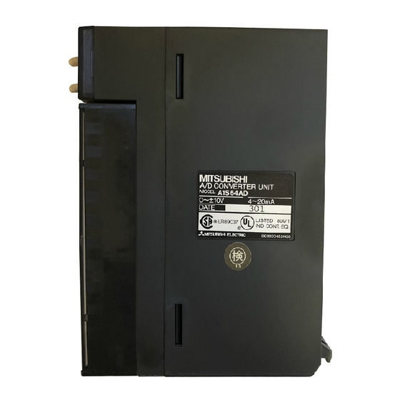
A/D Converter module
Thank you for buying the Mitsubishi general-purpose programmable
logic controller MELSEC-A Series
Prior to use, please read both this manual and detailed manual
thoroughly and familiarize yourself with the product.
©1994 MITSUBISHI ELECTRIC CORPORATION
type A1S64AD
User's Manual
MODEL
A1S64AD(H/W)-U-E
MODEL
CODE
IB(NA)-66485-D(0609)MEE
(Hardware)
13JE46
Advertisement

Subscribe to Our Youtube Channel
Related Manuals for Mitsubishi A1S64AD


Summary of Contents for Mitsubishi A1S64AD
- Page 1 A/D Converter module type A1S64AD User's Manual (Hardware) Thank you for buying the Mitsubishi general-purpose programmable logic controller MELSEC-A Series Prior to use, please read both this manual and detailed manual thoroughly and familiarize yourself with the product. MODEL A1S64AD(H/W)-U-E...
-
Page 2: Safety Precautions
Also pay careful attention to safety and handle the module properly. These precautions apply only to Mitsubishi equipment. Refer to the CPU module user's manual for a description of the PLC system safety precautions. -
Page 3: Wiring Precautions
[WIRING PRECAUTIONS] CAUTION If there are high levels of noise, ground the AG terminal and FG terminal with Class D grounding (Class 3 grounding) or higher dedicated for the PLC. Failure to observe this could lead to malfunctioning. When wiring in the PLC, be sure that it is done correctly by checking the product's rated voltage and the terminal layout. - Page 4 About the Manuals The following manuals are related to this product. Refer to the following table, and procure these manuals as necessary. Detailed Manual Manual No. Manual name (Model code) A/D converter module type A1S64AD User’s Manual IB-66336...
-
Page 5: Performance Specifications
1. Outline This manual explains the specifications and names of each part of the A1S64AD type analog/digital converter (hereinafter, A1S64AD) used in combination with the MELSEC-A Series PLC CPU module (hereinafter PLC CPU). 2. Performance Specifications The performance specifications of the A1S64AD are shown below. - Page 6 Item Specifications No. of occupied Special 32 points input/output points Connection 20-point terminal block terminal External power Not required supply Applicable wire 0.75 to 1.5mm size Applicable crimp 1.25-3, 1.25-YS3, V1.25-3, V1.25-YS3A terminal Internal current consumption 0.4A (5VDC) Weight 0.25kg *1: The gain is set to 5V and the offset to 0V as the default.
- Page 7 3. Names and Settings of Each Part 3.1 Names of each part The names of each A1S64AD part are shown below. 1S64AD OFFSET GAIN TEST...
- Page 8 Name Details RUN LED The operation state of the A1S64AD is indicated. Normal mode : In normal operation Flickering: Write data error has occurred. : 5V power OFF or watch dog timer error Test mode : OFF SET switch or GAIN switch is ON...
- Page 9 3.2 Setting the offset and gain Follow the procedure below to change the input/output conversion characteristics. Start Apply the voltage or current to be set as the offset value. Short-circuit the test mode terminal (across 1-2) For voltage TEST For current Actually connected resistance value Set the "channel selection switch"...
- Page 10 Apply the voltage or current to be set as the gain value. Adjust any other channels? For voltage Release the test mode terminal For current (across 1-2). TEST Actually connected resistance value Set the gain switch to "GAIN". GAIN Remarks The offset value and gain value have the following meanings.
- Page 11 4. Handling 4.1 Precautions for handling (1) The main body case and terminal block are made of resin, so do not drop them or apply strong impacts. (2) Do not remove the module PCB from the case. Doing so could lead to faults. (3) Make sure that foreign matter, such as wire scraps, does not enter from the top of the module during wiring.
- Page 12 A1S64AD functions to the fullest and creating a highly reliable system. The precautions for external wiring are given below. (1) Use separate cables for the alternating current and A1S64AD external input signals to eliminate the effect of surge or inductance on the alternating current side.
- Page 13 ANALOG *1: Use a 2-core twisted shield wire. *2: Indicates the A1S64AD input resistance. *3: For the current input, always connect with the (V+) and (I+) terminals. *4: If noise or ripple is generated in the external wiring, connect a. 0.1 to 0.47μF capacitor (approximate 25V or more withstand voltage) between the terminal V and COM.
-
Page 14: Outline Dimension Drawing
6. Outline Dimension Drawing 1S64AD OFFSET GAIN 93.6 (3.69) 34.5 (1.36) (0.26) (0.29) Unit:mm(in) - Page 16 Warranty Mitsubishi will not be held liable for damage caused by factors found not to be the cause of Mitsubishi; machine damage or lost profits caused by faults in the Mitsubishi products; damage, secondary damage, accident compensation caused by special factors unpredictable by Mitsubishi;...
Need help?
Do you have a question about the A1S64AD and is the answer not in the manual?
Questions and answers