
Related Manuals for Milwaukee M18 FMS184


Summary of Contents for Milwaukee M18 FMS184
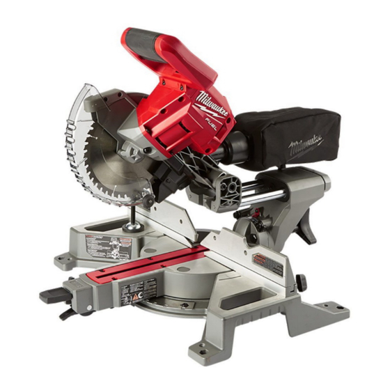
- Page 1 OPERATOR'S MANUAL Cat. No. M18 FMS184 M18 FUEL™ 184mm (7- 1/4") DUAL BEVEL COMPOUND SLIDING MITRE SAW WARNING To reduce the risk of injury, user must read and understand operator's manual.
-
Page 2: General Power Tool Safety Warnings
Dress properly. Do not wear loose clothing or GENERAL POWER TOOL jewelry. Keep your hair and clothing away from SAFETY WARNINGS moving parts. Loose clothes, jewelry or long hair can Read all safety warnings, instruc- WARNING be caught in moving parts. If devices are provided for the connection of dust tions provided with this power tool. - Page 3 100 mm from either side of the saw important information. If unreadable or missing, contact blade, to remove wood scraps, or for any other ® a MILWAUKEE service facility for a replacement. reason while the blade is spinning. The proximity Some dust created by power sanding,...
-
Page 4: Functional Description
19. Workpiece clamp 20. Bevel angle scale 21. Bevel angle pointer 22. Head lock-down pin 23.Slide rails SYMBOLOGY SPECIFICATIONS Cat. No..........M18 FMS184 Volts Volts.............. 18 DC Battery Type ..........M18™ Direct Current Charger Type..........M18™ Recommended Ambient No Load Revolutions per Minute (RPM) Operating Temperature....-17°C to 51°C... -
Page 5: Transporting And Storing
24. Trigger 27. Dust chute 30. Bevel knob 25. Trigger lock 28. Dust bag 31. 0° stop pin 26. Cut-line indicator switch (not shown) 29. Slide rail lock 32. Hand stop 33. Wrench storage (not shown) 34. 6 mm Hex Wrench 35. -
Page 6: Dust Collection
Dust collection 8. Install Collected sawdust from coated WARNING 9. Press in the spindle lock and rotate the blade until (polyurethanes, linseed oil, etc.) the lock engages. Insert and securely tighten the workpieces can self-ignite in the dust bag or blade bolt (counterclockwise) with the wrench. -
Page 7: Adjusting The Bevel Angle
Support the Workpiece Properly Adjusting the Bevel Angle Always support the workpiece during operation. The bevel can be adjusted to any angle from 0° to 48°, Otherwise, the workpiece may pull up and into the left or right. saw. WARNING! Use clamps to support the work- 1. -
Page 8: Operation
If the brake fails to stop the blade or 6. WARNING! Keep hands out of the No Hands ® misses frequently, return the tool to a MILWAUKEE Zone at all times during use. Contact with blade service facility for repair. - Page 9 Two Methods for Cutting Crown Molding APPLICATIONS The angles created on a piece of crown molding that Do not cut stone, brick, concrete, WARNING magnesium, or ferrous metals together, equal 90° (A + B = 90°).The most common (iron, steel, stainless steel, or alloys of these crown molding angles are : metals) with this saw.
-
Page 10: Maintenance
1. Top edge of molding against fence months to one year, depending on use, return the ® 2. Mitre table set right 31.62 tool, battery pack and charger to a MILWAUKEE ° service facility for inspection. 3. Save right end of cut If the tool does not start or operate at full power with Standard crown molding with 45°... - Page 11 9. Move the bevel adjustment lever to "lock". 10. Reassemble assembly, tightening the screws securely. 11. If necessary, loosen the left and right bevel pointer adjustment screws and reposition the pointers so that they indicates exactly zero. Once the pointers are properly positioned, re- tighten the bevel pointer adjustment screw.
- Page 12 SERVICE - AUSTRALIA and NEW ZEALAND MILWAUKEE ® prides itself in producing a premium quality product that is Nothing But Heavy Duty ® . Your satisfaction with our products is very important to us! If you encounter any problems with the operation of this tool, please contact your authorised MILWAUKEE ®...
Need help?
Do you have a question about the M18 FMS184 and is the answer not in the manual?
Questions and answers