fully Jarvis Assembly Instructions Manual
Hide thumbs
Also See for Jarvis:
- Installation manual ,
- Assembly instructions manual (29 pages) ,
- Quick start manual (9 pages)

Related Manuals for fully Jarvis


Summary of Contents for fully Jarvis
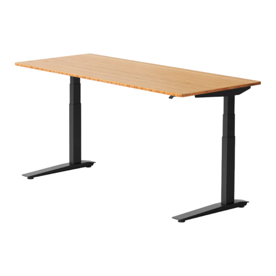
- Page 1 Jarvis crank-powered standing desk Assembly instructions For assembly assistance, visit fully.com/howtojarvis or call 888-508-3725 or email support@fully.com...
- Page 2 Thank you for choosing a Jarvis desk from Fully.
- Page 3 Cautions & Use Make sure the desk top is not in contact with any obstacles or walls. Make sure the desk top is not touching any walls. Make sure all cords are an appropriate length to accommo- date the full range of height adjustment. Do not sit or stand on the desk frame.
- Page 4 In the box wood screw x12 left lifting column M5x16 right lifting column large machine screw x16 M6x14 feet x2 left side bracket medium machine screw x12 right side bracket M6x10 frame ends x2 small machine screw x2 M5x10 center rails x2 hand crank right side crank rod left side crank rod...
-
Page 5: Before Starting
Before Starting On a padded or carpeted Pro Tip area, take all of the items out of your Jarvis frame box, Wood Screws: and confirm that nothing is Machine Screws: Pointy End Flat End missing. Tools 3mm hex key 5mm hex key... - Page 6 Assembly step 1 Insert the left lifting column (Part 1L - Labeled “L”) into the frame end (Part 4) as shown below. To secure the frame end to the leg, thread four (4) of the large machine screws (Part 15) into the holes as shown, but do not tighten them all the way.
- Page 7 If the pre-drilled holes have metal inserts, you will need to use the machine screws pack- Wood Screws: Pointy End aged with the Jarvis desk top to secure the frame; otherwise use five (5) wood screws front edge of Jarvis desk top...
- Page 8 step 6 Secure the left leg assembly with the remaining screws. Again, if the pre-drilled holes have metal inserts, you will need to use the machine screws packaged with the desk top to secure the frame; other- wise use five (5) wood screws (Part 14).
- Page 9 step 8 Assemble the driveshaft by sliding the two driving rod setscrew too tight sleeves (Part 9) over each end of the driving rod (Part 10). setscrew just right The sleeves have setscrews pre-inserted on both ends. Do not tighten setscrews until step 9.
- Page 10 Using the two (2) wood screws (Part 14), attach the adapter plate (Part 11) making sure that the “R” or “L” label matches your chosen orientation. If you have a Jarvis desk top, use the widely-spaced pre-drilled holes for this purpose.
- Page 11 step 13 Attach the plastic crank bushing to the adapter plate (Part 11) using the two (2) small machine screws (Part 17). Tighten the set screw on the crank sleeve. step 14 Loosely attach the feet (Part 2) to the bottom of the lifting columns with four (4) large machine screws (Part 15) per foot.
- Page 12 Desks, chairs & things to keep you moving 90.014.01.0499v.d...
Need help?
Do you have a question about the Jarvis and is the answer not in the manual?
Questions and answers