Table of Contents
Advertisement
Notice de fonctionnement
User's manual
Bedienungsanleitung
Libretto d'istruzioni
Manual de instrucciones
Copyright ©
MX 24B
MULTIMETRE NUMERIQUE
DIGITAL MULTIMETER
DIGITAL MULTIMETER
MULTIMETRO DIGITALE
MULTIMETRO DIGITAL
page 1
Chapitre
page 14
Chapter
Seite 28
Kapitel
pagina 42
Capitolo
página 56
Capítulo
X01877A00 - Ed. 4 - 02/04
I
II
III
IV
V
Advertisement
Table of Contents

Related Manuals for Metrix MX 24B


Summary of Contents for Metrix MX 24B
- Page 1 MX 24B MULTIMETRE NUMERIQUE DIGITAL MULTIMETER DIGITAL MULTIMETER MULTIMETRO DIGITALE MULTIMETRO DIGITAL Notice de fonctionnement page 1 Chapitre User's manual page 14 Chapter Bedienungsanleitung Seite 28 Kapitel Libretto d'istruzioni pagina 42 Capitolo Manual de instrucciones página 56 Capítulo Copyright ©...
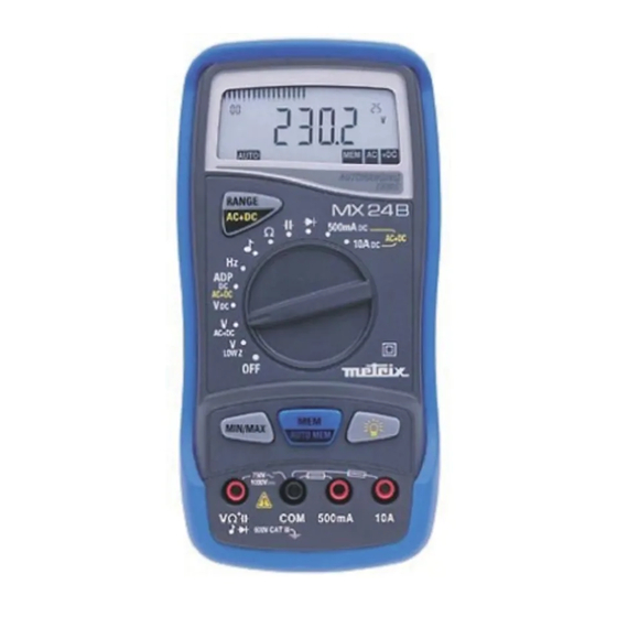
- Page 2 MX 24B 500mA 500mA Multimètre digital portable 5000 points, avec entrée courant...
-
Page 3: Table Of Contents
Chapter II USER’S MANUAL CONTENTS GENERAL INSTRUCTIONS........................15 1.1. Precautions and safety measures ....................15 1.1.1. Preliminary............................ 15 1.1.2. During use ............................ 15 1.1.3. Symbols............................16 1.1.4. Instructions ........................... 16 1.2. Protection devices ..........................16 1.3. Safety devices ..........................17 1.4. -
Page 4: General Instructions
Chapter II GENERAL INSTRUCTIONS You have just acquired a portable digital multimeter and we thank you for your confidence. This instrument complies with the specification of IEC 61010-1 + A1 + A2, 1995, con- cerning safety requirements for electronic measuring apparatus. To get the best service from this instrument, read carefully this user's manual and respect the detailed safety precautions. -
Page 5: Symbols
Chapter II ∗ When the multimeter is linked to measurement circuits, do not touch unused terminals. ∗ When the scale of the value to be measured is unknown, check that the scale initially set on the multimeter is the highest possible or, wherever possible, choose the autoranging mode. -
Page 6: Safety Devices
Chapter II ∗ Two HBC fuses provide protection up to 600 V during measurements of intensity type. ∗ An IP protection rating of 40. 1.3. Safety devices ∗ The battery unit cannot be accessed without first disconnecting the measuring leads. ∗... -
Page 7: Description
Chapter II DESCRIPTION This compact multimeter is a self-contained with an appropriate mechanical construction, enables hand-held version, with a protective elastomer case. It is designed for a high degree of user safety, maximum protection and unrivalled performance. 2.1. Selector switch This multimeter is a standalone, hand-held professional measuring instrument, capable of measuring the following quantities (accessed by the twelve-position rotary selector switch) : ∗... -
Page 8: Getting Started
Chapter II GETTING STARTED 3.1. Connecting the test leads Connect the black lead to the COM socket (for all measurements). Depending on the position of the selector switch, connect the red lead as follows: Input terminal Rotary selector switch position , Ω, V Ω... -
Page 9: Battery Self-Test
Chapter II 3.5.2. Battery self-test When the “BAT” indication appears on the display, the instrument still has approximately 12 hours of operation, but specifications can no longer be guaranteed. Replace the battery. Before changing the used battery, please ensure that the “Bat” symbol lights up, including when there is no signal at the multimeter input. -
Page 10: Functional Description
Chapter II FUNCTIONAL DESCRIPTION 4.1. RANGE / AC+DC key The RANGE key is operative in following positions of the selector switch : , Ω, LOW Z AC+DC This key makes it possible : • In AUTO (Autoraging) mode to switch to MANUAL mode (short press). •... -
Page 11: Adc / 10 Aac+Dc Position
Chapter II 4.1.3. 10 A / 10 A Position AC+DC 10 A DC current measurement (Range 10 A AC+DC key 10 A AC+DC The AC+DC sign AC+DC current measurement (TRMS) appears on the display. (Range 10 A AC+DC AC+DC key 4.2. -
Page 12: Technical Specifications
Chapter II TECHNICAL SPECIFICATIONS 5.1. General Only the values assigned tolerances or given limits are guaranteed values. Values without tolerances are given for information only, without guarantee (standard NFC 42670). The measurement errors must be considered in an environment of reference temperature (refer to §... -
Page 13: Dc Current
Chapter II 5.2.3. DC current Selector switch Ranges Accuracy Max voltage Protection Fuses Resolution (∗) position drop 500 mA 500 mA 0.3 %R + 2 D < 800 mV 600 V F1 + F2 100 µA (∗∗) 10 A 1 %R + 5 D <... -
Page 14: Capacitance
Chapter II 5.2.6. Capacitance Note Discharge all capacitors before taking measurements. Selector switch Ranges Accuracy Measurement Max measurement Protection Resolution (∗) position current time 50 nF 100 nA < 1 s 10 pF 500 nF 1 µA < 1 s 100 pF 5 µF 10 µA... -
Page 15: General Information
Chapter II 5.2.10. General information Mechanical Dimensions : 170 x 80 x 35 mm Weight (inc. battery) : 285 g Casing and circuit : self-extinguishing materials Packaging Dimensions : 230 x 155 x 65 mm Weight : 385 g Power supply Power requirements : single 9 V alkaline battery (6LF22) Low battery indication :... -
Page 16: Accessories
Chapter II 5.3. Accessories 5.3.1. Supplied with the multimeter One set of test leads with safety probes AG1063 One 6LF22 9 V battery AL0042 One user’s manual X01877A00 Protective elastomer case AE0237 5.3.2. Optional Probes EHT 3 kV HT0203 AC/DC EHT 30 kV HT0212 Type K thermocouple, 1 mV/°C, general purpose... - Page 17 Kapitel III BEDIENUNGSANLEITUNG INHALT 1. ALLGEMEINE HINWEISE ........................... 29 1.1. Vorsichtsmaßnahmen und Sicherheitsregeln ..................29 1.1.1. Vor der Benutzung.......................... 29 1.1.2. Bei der Benutzung .......................... 29 1.1.3. Symbole............................30 1.1.4. Anweisungen ..........................30 1.2. Schutzvorrichtungen..........................30 1.3. Sicherheitseinrichtungen ........................31 1.4.
Need help?
Do you have a question about the MX 24B and is the answer not in the manual?
Questions and answers