Table of Contents
Advertisement
Quick Links
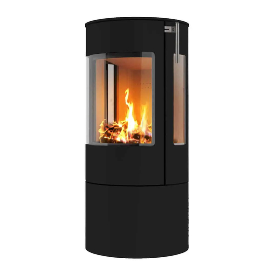
Installation & Operation Manual
RAIS VIVA L Direct Vent Gas Stove
This appliance may be installed in an aftermarket,
permanently located manufactured home (USA only) or in a
mobile home, where not prohibited by local codes.
This appliance is for use only with the type of gas indicated on
the rating plate. This appliance is not convertible for use with
other gases, unless a certified conversion kit is used.
Ce manual est disponsible en Français sur demande.
Report #
XXXXXXXX
1
AVERTISSEMENT
les instructions données dans cette notice pour
réduire au minimum le risque d'incindie ou
d'explosion ou pour éviter tout dommage
matériel, toute blessure ou la mort.
Ne pas entreposer ni utilizer d'essence ni d'autres
vapeurs ou liquides inflammables dans le voisinage
de cet appareil ou de tout autre appareil.
-QUE FAIRE SI VOUS SENTEZ UNE ODEUR DE
GAZ:
Ne pas tenter d'allumer d'appareil.
Ne touchez à aucan interrupteur. Ne pas
vous servir des téléphones se trouvant
dans le bâtiment où vous trouvez.
Appelez immédiatement votre
fournisseur de gaz depuis un voisin.
Suivezles instructions du fournisseur.
Si vous ne pouvez rejoindre le fournisseur
de gaz, appelez le service des incindie.
- L'installation et l'entretien doivent être assurés par
un installateur ou un service d'entretien qualifié ou
par le fournisseur de gaz.
Cet appareil peut être installé dans une maison
préfabriquée (mobile) déjà installée à demeure
si kes règlements locaux le permettent.
Cet appareil doit être uniquement avec las type
de gaz indiqué sur la plaque signalétique. Cet
appareil ne peut être converti à d'autres gaz,
sauf si une trousse de conversion est utilisée.
Ne pas utiliser cet appareils'il a été plongé,
meme partiellement, dans l'eau. Appeler un
technician qualifié pour inspecter l'appareail et
remplacer toute partie du système de commande
et toute commande qui a été plongée dans /'eau.
INSTALLATEUR: Laissez cette notice avec l'appareil.
COMSOMMATEUR: Conservez cette notice pour consultation ultérieur.
: Assurez-vous de bien suivre
Attention. Au moment de l'entretien des com-
mandes, étiquetez tous les fils avant de les dé-
brancher. Des erreurs de la câblage peuvent en-
traîner un fonctionnement inadequate et dan-
gereux.
S'assurer que l'appareil fonctionne adéquate-
ment une fois l'entretien terminé.
AVERTISSEMENT. Ne pas utiliser l'appareil
si le panneau frontal en verre n'est pas en place,
est craqué ou brisé. Confiez le remplacement du
panneau à un technician agree.
2
Advertisement
Table of Contents

Subscribe to Our Youtube Channel
Related Manuals for RAIS VIVA L Series


Summary of Contents for RAIS VIVA L Series
- Page 1 éviter tout dommage Installation & Operation Manual matériel, toute blessure ou la mort. RAIS VIVA L Direct Vent Gas Stove Ne pas entreposer ni utilizer d’essence ni d’autres vapeurs ou liquides inflammables dans le voisinage de cet appareil ou de tout autre appareil.
- Page 2 Do not use this appliance if any part has been under water. Immediately call a qualified service GININNG THE INSTALLATION OF THE RAIS GAS STOVE. ALTHOUGH THE BASIC RE- technician to inspect the appliance and to replace any part of the control system and any gas control QUIREMENTS FOR THE INSTALLATION OF ALL DIRECT VENT GAS HEATERS ARE which has been under water.
- Page 3 This appliance is equipped for use with the fuel type indicated on the rating plate. Fuel conversion kits that include 3711901 the necessary parts and instructions are included with the stove or are available from your installer, dealer or RAIS. This appliance has been certified by Intertek, Inc. to ANSI Z21.50 • CSA 2.22 Vented Gas Fireplace Heaters and CGA 2.17-M91 (R2009), Gas-Fired Appliances for Use At High Altitudes.
-
Page 4: Requirements For The Commonwealth Of Massachusetts
Installation. The gas stove is shipped with a flexible connector that has a 1/2” NPT female connection. The gas supply piping should have a separate gas shutoff valve and a 1/8” NPT plugged tapping upstream of the Several issues must be addressed when selecting a suitable location for your VIVA L. The minimum clear- valve. - Page 5 Horizontal Wall Vent Termination Flue sizing: ® The VIVA L Gas Stove has been tested and listed for installation with 4” X 6 5/8” Simpson DuraVent GS ⅝ VIVA L Ø4x6 Connector on Appliance. ® ® ® ® AmeriVent Direct , Selkirk DT , BDM Pro-Form DVS , ICC EXCEL Direct...
- Page 6 Vertical Roof Vent Termination Vertical Roof Termination Flue sizing: ⅝ VIVA L Ø4x6 Connector on Appliance. ⅝ Ø4x6 Maybe used Throughout, Alternatively, Ø5x8 Expander may be used, so that Ø5x8 flue can be used thereafter. ⅝ Flue Terminal: Ø4x6 Alternatively, Ø5x8 Minimum Vertical Flue Height: 20”(0.5m) Flue Restrictors to be fitted, Ø...
- Page 7 Vertical Roof Termination on angle Vertical Roof Termination with bends...
- Page 8 VENT TERMINAL CLEARANCES (Refer to illustration on page 15) PLEASE NOTE: If your specific venting configuration is over 15 feet (4.5m), you must use one of the approved direct vent venting systems that utilizes a stainless steel inner liner. This requirement is part of the ANSI standards and is based on testing conducted to determine where the exhaust gas temperature drops to the point where condensation might occur in the vent pipe.
- Page 9 UNPACKING AND PLACING THE VIVA L LOGS AND EMBERS By now, you will have removed the shipping carton from the base pallet. The VIVA L is shipped in a When arranging the Media into the Firebed, it is imporant that the Pilot area is kept clear and that no Media enters the specially designed shipping carton.
- Page 10 Log Lay Scatter the Bags of Embers over the top of the burners as shown, keeping the piot area clear. Position the 8 logs as shown, noting the 2 special logs labelled A and B. These have a slot cast Log 3 into the underside, this slot fits on top of the 2 raised burner sections.
- Page 11 After the logs and embers have been placed, the next step is to replace the glass panel and frame. Top or Rear Vent The VIVA L has provisions for either top or rear venting but is shipped from the factory set-up for top venting. The rear position is sealed with a special cover plate.
- Page 12 Fine-Tuning The recommended settings have been optimized based on extensive testing, however, additional adjustments may be required to accommodate specific installation circumstances. For example, a north wall installation GAS CONNECTION may require slightly different settings than a south wall. The VIVA L is shipped from the factory with a flexible gas connector that has a 1/2” NPT female Fine-tuning can be accomplished with the stove installed and operating.
-
Page 13: Lighting The Fire
LIGHTING THE FIRE FOR YOUR SAFETY READ BEFORE LIGHTING WARNING: If you do not follow these instructions exactly, a fire or explosion may result causing property damage, personal injury or loss of life. 22 ... - Page 14 24 ...
- Page 15 26 ...
- Page 16 The area around the injector should be inspected and any lint or foreign material must be removed with a brush or MAINTENANCE INSTRUCTIONS vacuum. A qualified service agency should conduct an annual inspection and maintenance of your VIVA L including the overall installation and venting to keep it running safely.
-
Page 17: Parts List
PARTS LIST. To be inserted here. INSPECTING THE VENTING An inspection of both the inner and outer vent pipes and the vent terminal should be made as part of the annual service appointment. The venting must have no blockage and be in good repair. The vent manufacturer’s instructions may provide specific details on vent inspection. -
Page 18: Appendix 1 - Dimension - Version Details
The installer should complete the form below that describes the details of the installation. Having this written record of installation information available will greatly expedite trouble-shooting should any problem arise with your stove. The installer should keep a duplicate of this form for their records. Manufactured by: RAIS A/S Industrivej 20 DK-9900 Frederikshavn Denmark www.rais.com... - Page 19 Viva 100 LG – with side glass Viva 120 L – without side glass 31 ...
- Page 20 Viva 120 LG – with side glass Viva 160 L – without side glass 33 ...
-
Page 21: Appendix 2 - Mertik Symax Controls
Viva 160 LG – with side glass Appendix 2 – Mertik Symax controls 35 ... - Page 22 GV60 Bidirectional Control System for use with Symax Handsets and myfire © © Installation and Operating Instructions INSTALLATION INSTRUCTIONS Thermostatic Mode ..............21 Program Mode .................21 Application ................. 3 myfire App ................22 Components ................3 Technical Specifications ............4 8-SYMBOL ................23 Mounting Positions ..............
-
Page 23: Important Safety Information
IMPORTANT SAFETY INFORMATION FOR OEM USE ONLY IMPORTANT SAFETY INFORMATION Read these instructions carefully and completely before installing or operating. Failure to follow them could result in a fire or explosion causing property damage, personal injury, or loss of life. Service and installation must be performed by a trained / experienced service technician. -
Page 24: Installation Instructions
INSTALLATION INSTRUCTIONS FOR OEM USE ONLY INSTALLATION INSTRUCTIONS APPLICATION GV60 is a battery-powered electronic remote ignition and control system for gas appliances with pilot burners and ODS systems. COMPONENTS 4-symbol Handset 8-symbol Handset 10-symbol Handset 6-symbol Handset B6R-H8(9)D6P… B6R-H8(9)TL3P... B6R-H8(9)TV...P... B6R-H8(9)T5P... - Page 25 INSTALLATION INSTRUCTIONS FOR OEM USE ONLY TECHNICAL SPECIFICATIONS Misc. cables: 221 °F Gas combination control according to CSA or CE approval Relay with Cable: 158 °F (see label for certification) Combination Control: 0 °C to 80 °C Latching Solenoid Valve: 0 °C to 80 °C APPROVALS Receiver without internal batteries: 0 °C to 80 °C CSA: Multifunctional gas control according to ANSI Z21.78...
-
Page 26: Myfire Wi-Fi Box
INSTALLATION INSTRUCTIONS FOR OEM USE ONLY MYFIRE WI-FI BOX ▪ WPA2 authentication ▪ AES 256-bitencryption security ▪ Compatible with IEEE 802.11n/g/b V MODULE CSA: Inlet: 115 VAC/60 Hz; 210 VA Outlet: 115 VAC/60 Hz; 100 VA each Built-in fuse 2.5 A Inlet: 230 VAC/50 Hz;... - Page 27 INSTALLATION INSTRUCTIONS FOR OEM USE ONLY NOTICE Main Gas (Pipe Connections) 1. Mertik Maxitrol does NOT recommend the use of Teflon / PTFE ® The use of the Mertik Maxitrol interrupter block is recommended. tape. Keep connection of interrupter block and thermocouple clean 2.
- Page 28 INSTALLATION INSTRUCTIONS FOR OEM USE ONLY MINIMUM REQUIREMENT SMART DEVICE: ▪ IOS 8.0 or Android 4.4 LED INDICATION ON MYFIRE WI-FI BOX (SEE FIGURE 14): Label Status Power on Figure 13: Synchronization in process Power Blue Power off NOTE: This is a one time setting only, and it is not required Connected to Home Network (Wi-Fi Router) after changing the batteries in the handset or receiver.
- Page 29 INSTALLATION INSTRUCTIONS FOR OEM USE ONLY BASIC Figure 16 8 / 34...
- Page 30 INSTALLATION INSTRUCTIONS FOR OEM USE ONLY ADDITIONAL FUNCTION: FAN – LIGHT / DIMMER – LATCHING SOLENOID Figure 17 9 / 34...
- Page 31 INSTALLATION INSTRUCTIONS FOR OEM USE ONLY THERMOCOUPLE OPTION Figure 18 10 / 34...
- Page 32 INSTALLATION INSTRUCTIONS FOR OEM USE ONLY RECEIVER FOR POWER FLUE CONTROL, FAN, LIGHT / DIMMER, LATCHING SOLENOID, AUX (VOLT-FREE CONTACT) Figure 19 11 / 34...
- Page 33 INSTALLATION INSTRUCTIONS FOR OEM USE ONLY MYFIRE APP SETUP Figure 20 12 / 34...
-
Page 34: Knob Settings
INSTALLATION INSTRUCTIONS FOR OEM USE ONLY KNOB SETTINGS ⅜ to ½ in. Knob function as follows (see figure 21): (10 to13 mm) KNOB POSITION FUNCTION Main valve knob Prevents main gas flow through valve. Thermocouple Permits main gas flow through valve Main valve knob if the pilot is lit and thermocouple is generating sufficient power. -
Page 35: Final Check
INSTALLATION INSTRUCTIONS FOR OEM USE ONLY 3. Place ON / OFF switch (if equipped) to the O (OFF) position. 4. Wait a minimum of five (5) minutes to clear out any gas. Verify that no gas is in the area around the appliance, including near the floor. -
Page 36: General Notes
OPERATING INSTRUCTIONS FOR OEM USE ONLY OPERATING INSTRUCTIONS GENERAL NOTES 3. The function icon will continue to flash until activation is com- plete. Activation is complete when the function icon is dis- NOTICE played. Wiring of valve and receiver must be completed before starting The following Functions can be Deactivated / Activated ignition. - Page 37 OPERATING INSTRUCTIONS FOR OEM USE ONLY NOTICE To connect myfire Wi-Fi Box to Wi-Fi Router (Home Network), make sure: ▪ Home Network is available. ▪ Home Network name and password are correct. ▪ SSID of the Wi-Fi Router is not hidden. ▪...
- Page 38 OPERATING INSTRUCTIONS FOR OEM USE ONLY 4-SYMBOL Child Proof Time Signal Indicator Battery Status Countdown Timer Fahrenheit or Celsius Temperature Figure 26: 4-symbol Display SETTING FAHRENHEIT or CELSIUS CHILD PROOF To change between °C and °F, press buttons simultaneously. To activate press buttons simultaneously.
-
Page 39: Countdown Timer
OPERATING INSTRUCTIONS FOR OEM USE ONLY ▪ Press button (One Button Ignition) ▪ To go to high fire, double-click but- button simultaneously ton. is displayed. (Two Button Ignition) until two short beeps and a blinking series of lines confirms the start sequence has be- gun;... -
Page 40: Setting Fahrenheit Or Celsius
OPERATING INSTRUCTIONS FOR OEM USE ONLY 6-SYMBOL Child Proof Time Signal Indicator Thermostatic Mode Battery Status Countdown Timer Fahrenheit or Celsius Program Mode Temperature Figure 27: 6-symbol Display SETTING FAHRENHEIT or CELSIUS CHILD PROOF To change between °C and °F, press buttons simultaneously. -
Page 41: Manual Mode (Handset)
OPERATING INSTRUCTIONS FOR OEM USE ONLY MANUAL MODE (HANDSET) DESIGNATED LOW FIRE and HIGH FIRE NOTICE NOTE: Backlight must be on for high fire and low fire double-click operation. BEFORE OPERATING 1. Make sure MANUAL knob on the GV60 valve is in the ON, ▪... - Page 42 OPERATING INSTRUCTIONS FOR OEM USE ONLY MODES of OPERATION PROGRAM MODE Thermostatic Mode The room temperature is measured and Press button. or , compared to the set temperature. The displayed. flame height is then automatically ad- justed to achieve the set temperature. ...
- Page 43 OPERATING INSTRUCTIONS FOR OEM USE ONLY MYFIRE APP selected NOTICE ON TIME SETTING (PROGRAM 1): displayed, is displayed Before the App can be used, the myfire Wi-Fi Box must be wired shortly, and hour flashes. and plugged into mains power according to myfire App setup 8.
- Page 44 OPERATING INSTRUCTIONS FOR OEM USE ONLY 8-SYMBOL Child Proof Time Signal Indicator Thermostatic Mode Battery Status Countdown Timer Fahrenheit or Celsius Program Mode Eco Mode Temperature Auxiliary Feature Figure 28: 8-symbol Display SETTING FAHRENHEIT or CELSIUS CHILD PROOF To change between °C and °F, press buttons simultaneously.
- Page 45 OPERATING INSTRUCTIONS FOR OEM USE ONLY MANUAL MODE (HANDSET) DESIGNATED LOW FIRE and HIGH FIRE NOTICE NOTE: Backlight must be on for high fire and low fire double-click operation. BEFORE OPERATING 1. Make sure MANUAL knob on the GV60 valve is in the ON, ▪...
- Page 46 OPERATING INSTRUCTIONS FOR OEM USE ONLY MODES of OPERATION PROGRAM MODE Thermostatic Mode The room temperature is measured and Press button. or , compared to the set temperature. The displayed. flame height is then automatically ad- justed to achieve the set temperature. ...
-
Page 47: Auxiliary Feature
OPERATING INSTRUCTIONS FOR OEM USE ONLY AUXILIARY FEATURE selected ON TIME SETTING (PROGRAM 1): Upon ignition burner 1 is on and burner 2 is in the last setting. displayed, is displayed shortly, and hour flashes. 8. To select hour press button. - Page 48 OPERATING INSTRUCTIONS FOR OEM USE ONLY 10-SYMBOL Child Proof Time Signal Indicator Thermostatic Mode Battery Status Countdown Timer Fahrenheit or Celsius Light Program Mode Eco Mode Temperature Auxiliary Feature Figure 29: 10-symbol Display SETTING FAHRENHEIT or CELSIUS CHILD PROOF To change between °C and °F, press buttons simultaneously.
- Page 49 OPERATING INSTRUCTIONS FOR OEM USE ONLY MANUAL MODE (HANDSET) DESIGNATED LOW FIRE and HIGH FIRE NOTICE NOTE: Backlight must be on for high fire and low fire double-click operation. BEFORE OPERATING 1. Make sure MANUAL knob on the GV60 valve is in the ON, ▪...
- Page 50 OPERATING INSTRUCTIONS FOR OEM USE ONLY MODES of OPERATION PROGRAM MODE Thermostatic Mode The room temperature is measured and Press button. or , compared to the set temperature. The displayed. flame height is then automatically ad- justed to achieve the set temperature. ...
-
Page 51: Circulating Fan Operation
OPERATING INSTRUCTIONS FOR OEM USE ONLY AUXILIARY FEATURE SELECTED ON TIME SETTING (PROGRAM 1): Upon ignition burner 1 is on and burner 2 is in the last setting. displayed, is displayed shortly, and hour flashes. 8. To select hour press button. - Page 52 OPERATING INSTRUCTIONS FOR OEM USE ONLY LIGHT / DIMMER OPERATION Press button ( displayed). Light is on at preset level. OFF: Press button ( disappears). SETTING: 1. Press button and hold until flash- 2. To adjust light between 20…100 % press button.
-
Page 53: Switch Panel
OPERATING INSTRUCTIONS FOR OEM USE ONLY SWITCH PANEL TOUCHPAD / WALL SWITCH Increase flame height A) Increase flame height ON/OFF B) ON/OFF Decrease flame height C) Decrease flame height Figure 30: Touchpad / Wall Switch Figure 31: Switch Panel To Turn ON Appliance To Turn ON Appliance ▪... -
Page 54: Manual Operation
OPERATING INSTRUCTIONS FOR OEM USE ONLY MANUAL OPERATION TO TURN OFF GAS TO APPLIANCE (Only possible, when MANUAL knob is used) 1. Place ON / OFF switch (if equipped) in O (OFF) position. Access to the pilot burner is only required for ignition with a 2. - Page 55 Exclusive Distributor Europe Exclusive Distributor North America for Maxitrol Company for Mertik Maxitrol Maxitrol Company Mertik Maxitrol GmbH & Co. KG 23555 Telegraph Rd., PO Box 2230 Warnstedter Str. 3, 06502 Thale Southfield, MI 48037-2230 GERMANY Tel: + 49 3947 400-0 Tel: + 1 248-356-1400 Fax: + 49 3947 400-200 Fax: + 1 248-356-0829...
Need help?
Do you have a question about the VIVA L Series and is the answer not in the manual?
Questions and answers