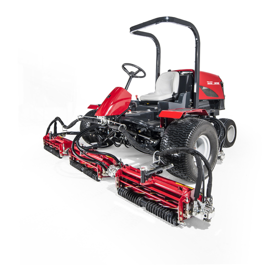
Baroness LM2400 Owner's Operating Manual
5-unit fairway mower
Hide thumbs
Also See for LM2400:
- Owner's operating manual (75 pages) ,
- Owner's operating manual (92 pages)

Subscribe to Our Youtube Channel
Related Manuals for Baroness LM2400


Summary of Contents for Baroness LM2400
- Page 1 5-Unit Fairway Mower Owner's Operating Manual "Required reading" Read this manual and the Owner's Manual for the engine before using the machine. Serial No. 10154- Original Instructions Ver.2.0...
- Page 2 LM2400 Greeting Thank you for purchasing the Baroness machine. This manual explains proper handling, adjustment, and inspection of your machine. Prior to use, carefully read this manual to thoroughly understand the contents for safe and correct operation. We hope you will use the machine safely, and take advantage of its best performance.
- Page 3 The information described in this manual is subject to change for improvement without prior notice. When replacing parts, be sure to use genuine Baroness parts or parts designated by Kyoeisha. Note that the Baroness product warranty may not apply to defects caused by the use of parts from other companies.
- Page 4 LM2400 Introduction Purpose This machine is intended for cutting turf grass at golf courses. Do not use this machine in any way other than its intended purpose, and do not modify the machine. Operating this machine for other purposes and modifying it may be very dangerous and may cause damage to the machine.
-
Page 5: Table Of Contents
LM2400 Contents Safety .............. Page 1-1 Safe Operating Practices .......Page 1-2 Disposal ............Page 2-1 Waste Disposal ..........Page 2-2 Product Overview .......... Page 3-1 Specifications ..........Page 3-2 Names of Each Section ......... Page 3-4 Safety Signs and Instruction Signs ....Page 3-6 Handling Instructions ........ - Page 6 LM2400 Contents...
-
Page 7: Safety
LM2400 Safety Safe Operating Practices ...... Page 1-2 Training ..........Page 1-2 Preparation ..........Page 1-2 Operation ..........Page 1-3 Maintenance and storage ...... Page 1-4 Page 1-1... -
Page 8: Safe Operating Practices
LM2400 Safety Failure to adequately follow these safety Incorrect hitching and load distribution precautions may cause an accident resulting in Never allow children or people unfamiliar injury or death. with these instructions to use or service the machine. Danger Danger... - Page 9 LM2400 Safety Check that operator's presence controls, Do the following before leaving the safety switches and shields are attached and operator`s position. functioning properly. Do not operate unless Stop on level ground. they are functioning properly. Disengage the power take-off and lower If the brake operation is faulty or the parking the attachments.
- Page 10 LM2400 Safety Take care when loading or unloading the Never allow untrained personnel to service machine into a trailer or a truck. Load or machine. unload the machine in a flat and safe place. Allow the engine/muffler to cool before Before loading or unloading, set the parking checking/maintenance.
- Page 11 LM2400 Safety Charge batteries in an open well ventilated area, away from spark and flames. Unplug charger before connecting or disconnecting from battery. Wear protective clothing and use insulated tools. Keep all parts in good working condition and all hardware tightened. Replace all worn or damaged decals.
- Page 12 LM2400 Safety Page 1-6 Safe Operating Practices...
-
Page 13: Disposal
LM2400 Disposal Waste Disposal ........Page 2-2 About the Waste disposal ...... Page 2-2 Page 2-1... -
Page 14: Waste Disposal
LM2400 Disposal Waste Disposal About the Waste disposal Make sure that waste generated when servicing or repairing the machine is disposed of in accordance with local regulations. (e.g. waste oil, antifreeze batteries, rubber products, and wires etc.) Page 2-2 Waste Disposal... -
Page 15: Product Overview
LM2400 Product Overview Specifications ........Page 3-2 Specifications .........Page 3-2 Sound pressure level ......Page 3-3 Sound power level ......... Page 3-3 Vibration level ........Page 3-3 Names of Each Section ......Page 3-4 Serial Number Plate .......Page 3-5 Specification Decal ........ Page 3-5 Noise Emission Decal ......Page 3-5... -
Page 16: Specifications
LM2400 Product Overview Specifications Specifications Type LM2400 Total length 303 cm During operation 318 cm Dimensions Total width During transport 226 cm Total height (steering wheel) 135 cm Weight 1,318 kg (with ROPS and empty fuel tank) Minimum turning radius... -
Page 17: Sound Pressure Level
LM2400 Product Overview Sound pressure level Sound pressure level This machine was confirmed to have a continuous A-weighted sound pressure level of 88 dB by measuring identical machines in accordance with the procedure specified in ISO5395-1:2013. Sound power level Sound power level... -
Page 18: Names Of Each Section
LM2400 Product Overview Names of Each Section Brake pedal Seat Hood Muffler Mower unit #3 Mower unit #5 Mower unit #1 Mower unit #4 Parking brake lock lever Traveling pedal Mower unit up/down lever Mower unit #2 Throttle lever Reel rotation switch... -
Page 19: Serial Number Plate
LM2400 Product Overview Serial Number Plate Year of Manufacture Decal The serial number plate indicates the model (For Europe) and serial number of the machine. The year of manufacture decal indicates the year when this machine was manufactured. YEAR OF... -
Page 20: Safety Signs And Instruction Signs
6iul4h-024 Positions of Safety Decals and Instruction Decals_002 Part numbers for decals that need to be replaced are listed in the parts catalog. Order them from a Baroness dealer or Kyoeisha. Positions of Safety Decals and Instruction Decals 6iul4h-025... - Page 21 LM2400 Product Overview 6iul4h-030 Positions of Safety Decals and Instruction Decals_006 Safety Signs and Instruction Signs Page 3-7...
-
Page 22: Description Of Safety Decals And Instruction Decals
LM2400 Product Overview Description of Safety Decals and Instruction Decals LM2400-0918Z0 Decal for operation 2 Warning Read the Owner's Operating Manual. Warning Apply the parking brake, stop the engine, remove the ignition key, and then leave the machine. Danger Danger Flying objects - All persons other than the operator must keep a safe distance from the machine. -
Page 23: Safety Signs And Instruction Signs
LM2400 Product Overview K4209000980 Hydraulic oil icon Read the Owner's Operating Manual. K 4 2 0 9 0 0 0 9 8 0 qigqnx-020 K4209001000 Diesel fuel icon Use diesel fuel. K 4 2 0 9 0 0 1 0 0 0... - Page 24 LM2400 Product Overview K4205001540 Decal for caution to hot parts Warning High temperature - Do not touch. Otherwise, you will get K 4 2 0 5 0 0 1 5 4 0 burned. qigqnx-022 K4205001710 Decal, caution for ROPS Replace a damaged ROPS.
-
Page 25: Handling Instructions
LM2400 Handling Instructions Inspection Before Use ......Page 4-2 Light Switch ......... Page 4-29 Throttle Lever ........Page 4-29 Reel Cutter (Cutting Cylinder) and Mower Unit Up/Down Lever ....Page 4-30 Bed Knife (Bottom Blade) ...... Page 4-2 Stop Valve ........... Page 4-30 Radiator Cover ........Page 4-2... -
Page 26: Inspection Before Use
LM2400 Handling Instructions Radiator Cover Inspection Before Use Inspection of Radiator Cover Be sure to perform an inspection before you start using the machine so that you will be able Make sure that there is no damage to the to take advantage of its optimum performance radiator cover. -
Page 27: Radiator
LM2400 Handling Instructions Pull the radiator cover to the back to open Radiator Inspection of Radiator For details on handling the engine, please refer to the separate Engine Operating Manual. Make sure that there is no damage to the radiator. -
Page 28: Coolant
LM2400 Handling Instructions Loosen the knobs on the left and right of Reserve tank the oil cooler, and then tilt the oil cooler. Coolant Supply For details on handling the engine, please refer to the separate Engine Handling Manual. Warning... - Page 29 LM2400 Handling Instructions If the coolant level in the reserve tank is Change of Coolant lower than the "LOW" mark, open the reserve tank cap and fill the tank with clean For details on handling the engine, please water up to the "FULL" mark.
-
Page 30: Oil Cooler
LM2400 Handling Instructions Oil cooler Hydraulic Oil Inspection of Oil Cooler Inspection of Hydraulic Oil Make sure that there is no damage to the The oil gauge is on the side of the hydraulic oil cooler. tank. Make sure that the oil cooler is not Raise the mower units and maintain that contaminated. - Page 31 LM2400 Handling Instructions Hydraulic Oil Supply Change of Hydraulic Oil Important Warning Do not mix different types of oil. When you change the hydraulic oil, be sure to drain it into a bowl and discard it in accordance with local laws and regulations.
-
Page 32: Air Cleaner
LM2400 Handling Instructions Remove the lid and open the tank cap, and Air Cleaner then pour new oil from the fill port until the oil level reaches the middle of the oil gauge Inspection of Air Cleaner on the hydraulic tank. -
Page 33: Battery
LM2400 Handling Instructions Attach the air cleaner element to the air Battery cleaner body. Inspection of Battery Replace the air cleaner cap, and then fix it securely with the clips. For details on handling the battery, please refer to the separate Battery Instruction Manual. -
Page 34: Tire
LM2400 Handling Instructions Tire Supply of Battery Fluid For details on handling the battery, please Inspection of Tires refer to the separate Battery Instruction Check the pneumatic pressure of the tires. Manual. Make sure that there are no cracks, Danger Danger damage or abnormal wear. -
Page 35: Belt
LM2400 Handling Instructions Belt Engine Oil Inspection of Belt Inspection of Engine Oil For details on handling the engine, please Caution refer to the Owner’s Manual for the engine. The engine must be stopped when the belt is Important inspected. - Page 36 LM2400 Handling Instructions Supply of Engine Oil Change of Engine Oil For details on handling the engine, please For details on handling the engine, please refer to the Owner’s Manual for the engine. refer to the separate Engine Handling Manual.
- Page 37 LM2400 Handling Instructions Re-place the drain plug. Remove the oil filler cap, and then supply new engine oil until the oil reaches a level in between the upper and lower limit lines on the oil level gauge. Engine oil quantity is approximately 3.1 dm (3.1 L).
-
Page 38: Fuel
LM2400 Handling Instructions If the fuel gauge located in the operation Fuel panel indicates a level close to E (EMPTY), supply fuel (diesel) at your earliest Inspection of Fuel Quantity convenience. With the machine on a level surface, observe the fuel gauge in the operation panel to check the fuel level. -
Page 39: Tightening Torques
LM2400 Handling Instructions Tightening torques Standard tightening torques Bolts and Nuts Important A number of bolts are used in each part of this machine. Be sure to re-tighten the bolts and nuts, because they may be loosened at the earlier stage of the use. - Page 40 LM2400 Handling Instructions Heat-treated bolt Strength classification 8.8 Strength classification 10.9 Nominal diameter 10.9 tib3yb-002 tib3yb-003 kgf-cm lb-in kgf-cm lb-in 5 - 7 50.99 - 71.38 44.26 - 61.96 7 - 10 71.38 - 101.97 61.96 - 88.51 8 - 11 81.58 - 112.17...
-
Page 41: Principal Tightening Torques
LM2400 Handling Instructions Principal tightening torques Tightening Torque by Model LM2400 Tighten the following bolts and nuts at the torque specified in the table. For thread locking adhesive, apply a middle strength thread locker (ThreeBond 1322 anaerobic adhesives). Tightening torque... -
Page 42: Adjustment Before Operating
LM2400 Handling Instructions Adjustment of Seat Adjustment Before Operating Use the seat adjustment levers to adjust the Adjustment of Steering Wheel seat. Adjust the position according to the operator's Warning body size. Since it is dangerous, do not adjust the Use the forward/backward adjustment lever steering wheel while traveling. -
Page 43: Adjustment Of Blade Engagement
LM2400 Handling Instructions With the cutter adjustment nut, adjust the Adjustment of Blade Engagement engagement between the reel cutter (cutting cylinder) and the bed knife (bottom blade) so Caution that newspaper (two to three sheets) will be cut by the edge of both blades when the blades in... -
Page 44: Adjustment Of Cutting Height
LM2400 Handling Instructions Adjustment of Cutting Height Reel cutter (cutting cylinder) Front roller Roller (Roller Type) Cutting height gauge Adjust the cutting height to fit your cutting Bed knife (Bottom blade) work. Cutting height adjustment nut A You can adjust the front roller in four stages. -
Page 45: Adjustment Of Reel Cover
LM2400 Handling Instructions Adjustment of Reel Cover Adjustment of CR Brush Note: Note: Depending on the specifications, this function Depending on the specifications, this function may not be available. may not be available. The angle of the reel cover can be adjusted. -
Page 46: Procedure To Start / Stop Engine
LM2400 Handling Instructions Open the fuel filter cock. Procedure to Start / Stop Engine The fuel filter is located on the left under the hood. Start / Stop of Engine Procedure to Start Engine Warning Before starting the engine, make sure that there are no other people or obstacles around the machine. - Page 47 LM2400 Handling Instructions Shift the throttle lever halfway from the Caution turtle icon (low speed) to the rabbit icon (high speed) position. Quickly returning the ignition key from the "START" position to the "ON" position may result in damage to the machine.
-
Page 48: Operation Of Each Section
LM2400 Handling Instructions Close the fuel cock of the sedimenter. Operation of Each Section Safety Mechanisms Precautions for Operating the Machine This machine features a safety device for starting/stopping the engine. Caution As for starting the engine, the safety device... - Page 49 LM2400 Handling Instructions 6n6oux-038 6n6oux-090 Instruction Decals_002 Instruction Decals_005 Decal, stop valve Decal, lapping switch 6n6oux-039 Instruction Decals_003 Decal, tilt steering 6n6oux-040 Instruction Decals_004 Decal, parking brake Operation of Each Section Page 4-25...
- Page 50 LM2400 Handling Instructions Decal, mower unit up/down lever It illustrates Up/Down of the mower unit. 1. Down 2. Up 6n6oux-041 STOP Decal, key switch It illustrates the position of the key switch. 1. OFF 2. ON 3. GLOW 4. START...
- Page 51 LM2400 Handling Instructions Decal, slight lift switch It illustrates ON/OFF of the slight lift function. 1. ON 2. OFF 6n6oux-043 Decal, light switch It illustrates ON/OFF of the light. 1. ON 2. OFF 6n6oux-044 K4203001290 Decal, stop valve It illustrates Stop/Open of the stop valve.
- Page 52 LM2400 Handling Instructions K4209001200 Decal, brake It illustrates the locking position for the parking brake. 6n6oux-092 K4203001580 Decal, lapping switch It illustrates ON/OFF change-over of backlapping operation. 1. ON 2. OFF 6n6oux-093 Page 4-28 Operation of Each Section...
-
Page 53: Light Switch
LM2400 Handling Instructions Light Switch Throttle Lever The throttle lever is located in the operation Warning panel and enables you to adjust the engine rpm. The lights provide auxiliary lighting. Move the throttle lever toward the rabbit icon Do not travel or operate the machine at night (high speed) to increase the engine rpm, and or under poor visibility. -
Page 54: Mower Unit Up/Down Lever
LM2400 Handling Instructions Note: Mower Unit Up/Down Lever Even if the reel rotation switch is set to the "Rotate" position, the reel cutter (cutting Caution cylinder) stops rotating when the mower unit up/down lever is moved to the neutral position Before raising or lowering the mower units, or the mower units are raised. -
Page 55: Mower Lock Lever (Latch)
LM2400 Handling Instructions Mower Lock Lever (Latch) Reel rotation switch Caution Caution When the mower lock levers (latches) are The reel rotation switch must be set just engaged, do not operate the mower unit up/ before you start cutting work. In cases other down lever. -
Page 56: Slight Lift Function
LM2400 Handling Instructions Slight Lift Function Reel Reverse Switch Note: Caution Depending on the specifications, this function may not be available. Do not switch the reel reverse switch to the "ON" or "OFF" position while the reel cutter Caution (cutting cylinder) is rotating. -
Page 57: Reel Rotation/Stop Switching Lever
LM2400 Handling Instructions Reel Rotation/Stop Switching Lever Traveling Pedal Caution Warning Before operating the reel rotation/stop This machine is not authorized as a special switching lever, be sure to shift the reel motor vehicle. Do not drive it on public roads. -
Page 58: Parking Brake Lock Lever
LM2400 Handling Instructions Parking Brake Lock Lever Hood Caution Caution Be sure to release the parking brake before Do not open the hood in strong winds. driving. Otherwise, it may cause the malfunction of the Caution brake or hydraulic system. -
Page 59: Underseat Cover
LM2400 Handling Instructions Insert the washer, then the pin. Lift the seat. Securely support the underseat cover with the seat support rod. i5jb7e-009 Hood_003 ljffir-011 Underseat Cover_002 Washer Seat Hood Seat support rod Underseat cover Step 1 Step 2 Caution Be careful not to pinch your fingers when you open or close the underseat cover. -
Page 60: Instruments
LM2400 Handling Instructions Hour meter Instruments The hour meter is located at the back of the Instruments on the Operation Panel operation panel, and indicates the total operation time of the engine. Every six minutes of engine operation will increase the number at the first digit (black number on a white background) by one. -
Page 61: Water Temperature Gauge
LM2400 Handling Instructions Water Temperature Gauge The water temperature gauge is located in the operation panel. This instrument indicates the water temperature inside the engine. If the water temperature gauge indicates a level close to "H" during operation, the machine is overheated. -
Page 62: Pilot Lamps
LM2400 Handling Instructions Pilot Lamps Thermo-start lamp Oil Pressure Lamp Charge Lamp The oil pressure lamp is the right pilot lamp The charge lamp is the left pilot lamp located located in the operation panel. in the operation panel. It turns on when the ignition key is set to the It turns on when the ignition key is set to the "ON"... -
Page 63: Travel Of Machine
LM2400 Handling Instructions Towing the Machine Travel of Machine If the machine does not travel due to engine Traveling Procedure trouble, etc., you can move it in the following Start the engine. (See "Procedure to Start ways: Engine" (Page 4-22) .) -
Page 64: Cutting Work
LM2400 Handling Instructions Depress the brake pedal to release the Set the reel rotation switch to the "Rotate" parking brake. position to rotate the reel cutters (cutting cylinders) for all mower units. Tow the machine slowly. Depress the traveling pedal to start cutting Cutting Work work. -
Page 65: Maintenance
LM2400 Maintenance Maintenance Precautions ..... Page 5-2 Maintenance Schedule ......Page 5-3 Specified Values ........Page 5-4 Main Consumable Parts ......Page 5-4 Jacking up the machine ......Page 5-5 About the Jacking up the machine ..Page 5-5 Jack-up Points ........Page 5-5 Greasing .......... -
Page 66: Maintenance Precautions
Use tools appropriate for each maintenance operation. Caution For the safe and best performance of your machine, use Baroness genuine parts for replacement and accessories. Please note that our product warranty may be void if you use non-genuine parts for replacement or accessories. -
Page 67: Maintenance Schedule
LM2400 Maintenance Maintenance Schedule LM2400 Follow the maintenance schedule below. ○・・・Inspect, adjust, supply, clean ●・・・Replace (first time) △・・・Replace Maintenance item Tightening the parts ○ Fuel ○ Air cleaner ○ △ 8 hrs. Engine oil ○ ● △ (first time) 50 hrs. -
Page 68: Specified Values
LM2400 Maintenance Maintenance item Hydraulic motor oil Power unit oil Transmission oil Hydraulic hose (moving part) ○ △ Hydraulic hose (fixed part) ○ △ Electromagnetic pump filter ○ △ Fuel strainer ○ △ Sedimenter ○ Fuel hose ○ Cleaning the exterior ○... -
Page 69: Jacking Up The Machine
LM2400 Maintenance Jacking up the machine Jack-up Points Front right frame About the Jacking up the machine Front left frame Rear frame Warning Pivot When replacing a tire or beginning any other Front left frame maintenance or repairs, be sure to chock the wheels to prevent the machine from moving. -
Page 70: Maintenance (Mower)
LM2400 Maintenance Pivot There are two locations. rwyt62-061 Jack-up Points_005 Page 5-6 Jacking up the machine... -
Page 71: Greasing
LM2400 Maintenance Greasing No. of Location greasing About Greasing points Pedal shaft fulcrum Since there may be adhesion or damage due Lift arm fulcrum to lack of grease on moving parts, they must be greased. Mower unit fulcrum Add urea-based No. 2 grease in accordance Front roller with the Maintenance Schedule. - Page 72 LM2400 Maintenance Mower unit #5 Front roller There is one greasing point each on the left and right of each mower unit. 8bq62b-175 Greasing Points_004 8bq62b-178 Mower units #2/#3 Greasing Points_007 Reel housing There is one greasing point on the reel housing of each mower unit.
- Page 73 LM2400 Maintenance Pivot Cylinder shaft There are three locations. #4 and #5 cylinder shafts Middle between the rear wheels Apply lubricant to the cylinder shafts (one point each on the left and right). 8bq62b-181 8bq62b-184 Greasing Points_010 Rear left wheel...
- Page 74 LM2400 Maintenance Power steering cylinder shaft Middle between the rear wheels Apply lubricant to the round end of the cylinder. 8bq62b-211 Greasing Points_016 Rear left wheel Apply lubricant to the round end of the cylinder. 8bq62b-212 Greasing Points_017 Page 5-10...
-
Page 75: Back Lapping Of Reel Cutter
Maintenance Have the following items ready: Strips of Maintenance (Mower) newspaper, Abrasive [Back lapping powder mixed with oil; or gel compound (Baroness Back Lapping of Reel Cutter (Cutting genuine abrasive)], Brush. Cylinder) Back lapping is work similar to sharpening a cooking knife. - Page 76 LM2400 Maintenance Shift only the reel rotation/stop switching Caution levers of the hydraulic motors in the mower units to be used for back lapping to the Before cutting newspaper as a test, be sure to "Rotate" position. stop the engine and wear gloves to protect Shift the levers to the "Stop"...
-
Page 77: Maintenance (Main Body)
LM2400 Maintenance Set the reel rotation switch to the "Rotate" Set the reel reverse switch to the "OFF" position to rotate the reel cutters (cutting position. cylinders) for back lapping. kp6cmu-003 mh4pyw-010 Back Lapping of Reel Cutter (Cutting Cylinder)_005 Back Lapping of Reel Cutter (Cutting Cylinder)_004... - Page 78 For installing the rear tires, reverse the Caution removing procedure. Refer to the Tightening Torque table. Note that the Baroness product warranty may not apply to defects caused by incorrect or overtorque tightening etc. Important Tighten the bolts in the tightening order (diagonally).
-
Page 79: Adjustment Of Belt Tension
LM2400 Maintenance Adjustment of Belt Tension Adjustment of Parking Brake Caution Danger Danger Be sure to stop the engine before adjusting If the brake wire is cut, the machine will be the belts. unable to stop. This would be extremely dangerous. -
Page 80: Adjustment Of Brake
LM2400 Maintenance Adjustment of Brake Adjusting the Neutral Position of the Piston Pump Danger Danger Caution If the brake wire is cut, the machine will be unable to stop. This would be extremely Make sure not to touch rotating tires. -
Page 81: Long-Term Storage
LM2400 Maintenance Change of Fuse Glow lamp timer Glow lamp Fuse Box Fuel pump Charge lamp, oil pressure lamp (engine oil Warning pressure lamp), water temperature gauge, Before performing maintenance on the buzzer, hour meter, fuel gauge electrical system, be sure to disconnect the... - Page 82 LM2400 Maintenance Page 5-18 Long-Term Storage...
- Page 86 MEMO...
- Page 87 Head Office 1-26, Miyuki-cho, Toyokawa, Tel : (0533) 84 - 1390 Fax : (0533) 89 - 3623 Aichi-Pref. 442-8530 Japan. LM2400--UM--GBZ/15M-00-S.K...
Need help?
Do you have a question about the LM2400 and is the answer not in the manual?
Questions and answers