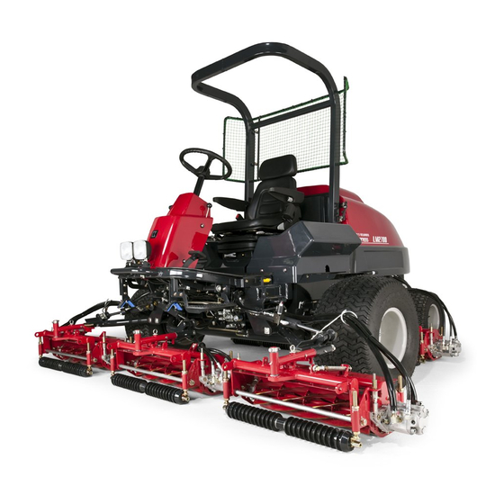
Baroness LM2700 Owner's Operating Manual
5-unit reel mower
Hide thumbs
Also See for LM2700:
- Service manual (325 pages) ,
- Owner's operating manual (46 pages) ,
- Operator's manual (44 pages)

Related Manuals for Baroness LM2700


Summary of Contents for Baroness LM2700
- Page 1 Owner's Operating Manual 5-Unit Reel Mower Required reading Read this manual and the Owner's Manual for the engine before using the machine. Serial No.11185- Original lnstructions Ver.3.3...
-
Page 2: Table Of Contents
Contents Greeting ........................1 Handling Instructions ....................13 Keeping the owner's operating manual ..............1 5. Inspection Before Use ..................13 Introduction ........................1 5-1 Inspection and Cleaning of Radiator and Oil Cooler ........13 Warning Symbols .....................2 5-2 Inspection and Supply of Coolant ............13 Precautionary Statement ..................2 5-3 Inspection and Supply of Hydraulic Oil ............14 Purpose ........................2 5-4 Inspection and Cleaning of Air Cleaner ............14... - Page 3 8. Start / Stop of Engine ..................25 11. Moving The Machine ..................34 12. Towing ......................35 8-1 Procedure to Start Engine ................25 13. Cutting Work ....................36 8-2 Procedure to Stop Engine ................25 14. Transportation ....................36 8-3 Safety Mechanisms ..................26 8-4 Warning Mechanisms................26 15.
-
Page 4: Greeting
−1− Greeting Introduction Thank you for purchasing the Baroness product. Read this manual carefully to ensure that you thoroughly understand how to properly operate and maintain the product, and to avoid causing injury to yourself or others. This manual describes the proper handling, adjustment, and inspection of your product. -
Page 5: Warning Symbols
Kyoeisha. This symbol indicates the articles regarding “Danger,” “Warning,” or “Caution.” Note that the Baroness product warranty may not apply to defects caused by the use of Those articles describe important safety precautions and so read them carefully to parts from other companies. -
Page 6: Safety
−3− Safety themselves ,other people, or property. 6. Keep in mind that the owner, operator, and mechanic are responsible for accidents or hazards occurring to other people or their property. Failure to adequately follow these safety precautions may cause an accident resulting in 7. -
Page 7: Operation
Operation [5] Before checking, cleaning or working on the machine. [6] After striking a foreign object or if an abnormal vibration occurs. 1. Do not operate the engine in a confined space where dangerous carbon monoxide Inspect the machine for damage and make repairs before restarting and operating fumes can collect. -
Page 8: Maintenance And Storage
−5− Maintenance and Storage between moving blades and fixed parts of the machine. 20.On multi-cylinder/multi-reel machines, take care as rotating one cylinder/reel can cause 1. Disengage drives on level ground, lower the atattachments, set parking brake, stop other cylinders/reels to rotate. engine and remove key from ignition. -
Page 9: Disposal
Disposal Recycle and Waste Disposal About Recycle Recycling battery etc. is recommended for environmental conservation and economical use of resources. It may be required by local laws. About The Waste Disposal Make sure that waste generated when servicing or repairing the machine is disposed of in accordance with local regulations. -
Page 10: Product Overview
ISO 5395-1:2013. ■ Sound Power Level ■ Specifications This machine was confirmed to have a sound power level of 103dB by measuring Model LM2700 identical machines in accordance with the procedure specified in directive 2000/14/EC. Mower unit type 26in 22in ■... -
Page 11: Names Of Various Sections
2. Names of Various Sections Roof Seat Throttle lever Tilt lever Mower unit raise/ Parking brake lever lower lever Radiator Brake pedal Operation panel Hood Oil cooler Fuel filler hole Forward pedal Oil level gauge Reverse pedal Light Muffler exhaust port Mower unit #2 Mower unit #4 Mower unit #3... -
Page 12: Regulation Decals
−9− 3. Regulation Decals 3-2 Description of Regulation Decals ■ Serial number plate 3-1 Positions of Regulation Decals The serial number plate indicates the model and serial number of the machine. <Operation panel> ROPS Compliance Decal ROPS Caution Decal ■ Specification Decal Noise Emission Decal (For Europe) - Page 13 ■ ROPS Compliance Decal The ROPS compliance decal indicates the manufacturer, model, etc., in accordance with International Standard ISO 21299:2009. ■ ROPS Caution Decal ROPS caution decal describes the caution messages compliant with ISO 21299:2009. Replace damaged ROPS. Do not repair or revise. (Only if equipped with ROPS) ■...
-
Page 14: Safety Decals And Instruction Decals
Part numbers for decals that need to be replaced are listed in the parts catalog. Order them from a Baroness dealer or Kyoeisha. K4205001970 4-2 Positions of Safety Decals and Instruction Decals K4205001970 <Operation panel>... -
Page 15: Description Of Safety Decals And Instruction Decals
Placing your hand near the fan and the belt while the engine is running might result in injury. K4205001530 : Hot surface Caution Do not touch. It can cause burns. LM2700-0959Z0 K4205001540 : Read the Operator's manual. Warning : Pinch Caution... -
Page 16: Handling Instructions
−13− Handling Instructions 5-2 Inspection and Supply of Coolant Caution Do not touch the radiator or coolant during engine operation 5. Inspection Before Use or immediately after the engine has been turned off. Be sure to perform an inspection before you start using the machine so that you will be able to take advantage of its optimum performance for a long period of time. -
Page 17: Inspection And Supply Of Hydraulic Oil
5-3 Inspection and Supply of Hydraulic Oil 5-4 Inspection and Cleaning of Air Cleaner The oil gauge is on the hydraulic tank. Inspect the air cleaner by checking the vacuum indicator. Check with the mower units lowered on a level surface. If the air cleaner element is contaminated, the vacuum indicator will display a red ring. -
Page 18: Inspection Of Battery And Supply Of Battery Fluid
−15− 5-5 Inspection of Battery and Supply of Battery Fluid Before inspection of battery, clean the areas UPPER LEVEL around the battery fluid level lines with a cloth LOWER LEVEL dampened with water. Danger ● When removing the battery, remove the negative (-) cable Make sure that the battery fluid level is between first, and positive (+) cable last. -
Page 19: Inspection Of Brake
5-7 Inspection of Brake 5-10 Inspection of The Engine and Its Surroundings 1) Check the parts of the fuel system for crack and leakage, and replace with new ones if ■ Foot brake necessary. While traveling, depress the brake pedal firmly to make sure that the brake is applied 2) When the grass, the leaf, etc. -
Page 20: Inspection And Supply Of Fuel
−17− Important Do not supply too much engine oil. Otherwise, the engine may Supply fuel after the engine is stopped and has well cooled Warning be damaged. down. With the machine on a level surface, observe Important Do not mix different types of engine oil. the fuel gauge in the operation panel to check the fuel level. -
Page 21: Inspection Of Fuel Filter
5-14 Inspection of Fuel Filter The fuel filter is positioned between the fuel strainer and the engine, and cleans the fuel flowing into the carburetor. When the fuel flow becomes insufficient, replace the fuel filter if necessary. 1) Make sure that there is no fuel leakage. 2) Make sure that the fuel filter is not damaged or dirty. -
Page 22: Fastening Of Each Portion
−19− 6. Fastening of Each Portion Important Refer to the Tightening Torque table. Note that the Baroness product warranty may not apply to defects caused by incorrect or overtorque tightening, etc. 6-1 Standard Tightening Torques Important A number of bolts are used in each part of this machine. Be sure to re-tighten the bolts and nuts, because they may be loosened at the earlier stage of the use. -
Page 23: Tightening Torque By Model
6-2 Tightening Torque by Model LM2700 Tighten the following bolts and nuts at the torque specified in the table. For thread locking adhesive, apply a middle strength thread locker (ThreeBond 1322 or equivalent anaerobic sealant). Tightening torque Thread locking Location... -
Page 24: Adjustment Before Operating
−21− 7. Adjustment Before Operating 7-3 Adjustment of Blade Engagement 7-1 Adjustment of Steering Wheel Make sure that the parking brake is firmly applied before Warning performing the operation. Since it is dangerous, do not adjust the steering wheel while Warning traveling. -
Page 25: Cutting Height Adjustment
7-4 Cutting Height Adjustment 3) Adjust the front roller. [1] Loosen the cutting height adjustment Cutting height adjusting nut nuts, and then adjust the front roller so Caution Do not perform the operation with any other persons. that it comes into contact with the cutting height gauge. -
Page 26: Adjustment Of Cutter Adjustment Spring
−23− 7-5 Adjustment of Cutter Adjustment Spring 7-7 Adjustment of Groomer Note: Depending on the specifications, this function may not be available. If the diameter of the reel cutter (cutting cylinder) becomes smaller, adjust the cutter adjustment spring. Important Adjust the groomer height so that it is the same level on the 1) Adjust the blade engagement. -
Page 27: Adjustment Of Groomer Spring
7-9 Adjustment of CR Brush Important Adjust the position so that the vertical blade can make contact Note: Depending on the specifications, this function may not be available. with the small screw for groomer setup. 6) Adjust the groomer height with the groomer Important Pressing the brush against the roller too tightly could cause Front roller... -
Page 28: Start / Stop Of Engine
−25− 8. Start / Stop of Engine 6) Switch the ignition key to the "GLOW" Key switch position. 7) Make sure that the glow plug is generating Caution ● When the engine is cold, be sure to warm it up. Failure to Glow heat and the thermo-start lamp is turned on. -
Page 29: Safety Mechanisms
8-3 Safety Mechanisms 8-4 Warning Mechanisms This machine features a safety device for starting/stopping the engine. Important When the buzzer (intermittent tone) sounds, be sure to stop 1) As for starting the engine, the safety device prevents the engine from starting unless it operation since the engine is overheated. -
Page 30: Operation Method Of Each Part
−27− 9. Operation Method of Each Part 9-3 Positions and Descriptions of Operation Panel Marks 9-1 Precautions for Operating The Machine Caution ● Check whether the operation state of each part is good, and the brake disc, tires, steering, and mower do not have abnormalities in particular before operating the engine. -
Page 31: Switch And Levers On The Operation Panel
9-4 Switch and Levers on The Operation Panel Select “Travelling” Press switch to the "Travelling" position, #4 & #5 mower units raise to top. Press switch to the a. Travelling –Mowing changeover switch e. Pilot lamp "Operating" position, #4 & #5 mower units raise b. -
Page 32: Reel Rotation Switch
−29− 9-7 Reel Rotation Switch 9-8 Reel Reverse Switch Caution Set the reel rotation switch to the "Rotation" position Important Do not switch the reel reverse switch to the "Reverse rotation" immediately before starting cutting work. At all other times, be or "Normal rotation"... -
Page 33: Mower Unit Raise / Lower Lever
9-12 Brake Pedal 9-10 Mower Unit Raise / Lower Lever To stop the machine, depress the brake pedal Caution Before raising or lowering the mower units, make sure that when needed. there are no people around the machine. Caution Pay attention if you put the key switch ON position, when the engine stops and mowing units raise/lower lever is DOWN position, then the mowing units would lower. -
Page 34: Forward / Backward Pedal
−31− 9-14 Forward / Backward Pedal 9-16 Mower Lock Lever (Latch) The mower lock levers (latches) are located in Mower lock lever Caution When the machine travels high speed, it does not stop the foot area on the left and right sides and are immediately even if you release the travelling pedals. -
Page 35: Reel Rotation / Stop Switching Lever
9-18 Reel Rotation / Stop Switching Lever 9-20 Hood Caution Do not open the hood in strong winds. Caution Before operating the reel rotation/stop switching lever, be sure to shift the reel rotation switch to the "Stop" position. Caution The reel rotation/stop switching lever is located When you open or close the hood, be careful not to pinch your on the reel motor attached to each mower unit. -
Page 36: Measuring Instrument
−33− 10. Measuring Instrument 10-4 Fuel Gauge It indicates current fuel level in the fuel tank. 10-1 Instruments of Operation Panel a. Tachometer & hour meter b. Water temperature gauge c. Fuel level gauge d. Pilot lamp F U E L •... -
Page 37: Oil Pressure Lamp (Engine Oil Pressure Lamp)
11. Moving The Machine 10-7 Oil Pressure Lamp (Engine Oil Pressure Lamp) It turns on when the ignition key is set to the Engine oil pressure lamp "ON" position before the engine starts. It turns Caution Under any circumstances drive the machine at such a speed off when the engine starts and engine oil that you can stop it immediately for emergencies. -
Page 38: Towing
−35− 12. Towing 9) Turn the unload valve, located beside the hydraulic pump, 90 degrees (so that it is If the machine does not travel due to engine trouble, etc., you can move it by towing it. vertical) to open it. 10) Put the seat back into place. -
Page 39: Cutting Work
13. Cutting Work 14. Transportation When using a truck or trailer for transporting, drive the machine forward to load it and in re- Do not start to move or stop the machine abruptly. Warning verse to unload it. To do so is very dangerous. In addition, it may damage the If the roof is installed on the machine, remove it. -
Page 40: Maintenance
○ For the safe and best performance of your machine, use Cleaning of radiator and oil cooler Baroness genuine parts for replacement and accessories. ○ Inspection of coolant Please note that our product warranty may be void if you use ○... -
Page 41: Jacking Up The Machine
17. Jacking Up The Machine 17-2 Jack-Up Points 17-1 About Jacking Up The Machine ● When replacing a tire or beginning any other maintenance or Warning repairs, be sure to chock the wheels to prevent the machine from moving. ● Before jacking up the machine, park it on a hard, flat surface such as a concrete floor and remove any obstacles that could prevent you from performing the work safely. -
Page 42: Greasing
−39− 3) Center of pivot 18-2 Greasing Points (Main Vehicle) Grease nipples are installed in the following locations. Caution The jack-up point of the center of the pivot is not the center of Add grease every 50 hours of operation. the machine. -
Page 43: Greasing Points (Mower Units)
19. Maintenance Work 18-3 Greasing Points (Mower Units) Grease nipples are installed in the following locations. 19-1 Swiveling Mower Units #2 and #3 Carry out the greasing up periodically to each part grease fitting. The parts greasing up every 10 hours is using the needle bearing. Be careful of the Caution Both the reel cutter (cutting cylinder) and the bed knife lubrication interval. -
Page 44: Cleaning Of Mower Unit
−41− 4) Fully insert the grip pin into the locking hole 19-2 Cleaning of Mower Unit for maintenance, and then install the clip pin in the grip pin. Important While cleaning, do not allow water on the sealed parts of the reel shaft. - Page 45 1) Prepare newspaper cut into strip, abrasive 14) Apply abrasive to a brush, and apply evenly to areas of the reel cutter that are sharp with back lapping powder mixed with oil or using the chalk markings as a guide. (Never apply it to areas that have poor sharpness.) Back lapping powder Brush g e l c o m p o u n d ( B a r o n e s s g e n u i n e...
-
Page 46: Sharpening Of Reel Cutter (Cutting Cylinder)
Sharpening is necessary when the reel cutter (cutting cylinder) reaches a condition de- For sharpening the reel cutter (cutting cylinder), contact your dealer or Baroness. scribed below. If the outer diameter of the reel cutter (cutting cylinder) after sharpening is more than the 1) When the sharpening width (length of contacting surface of bed knife (bottom blade)) for usage limit, the reel cutter (cutting cylinder) can be sharpened. -
Page 47: Replacement Of Reel Cutter (Cutting Cylinder)
19-5 Replacement of Reel Cutter (Cutting Cylinder) 19-6 Replacement of Bed Knife (Bottom Blade) Caution Both the reel cutter (cutting cylinder) and the bed knife Caution Both the reel cutter (cutting cylinder) and the bed knife (bottom blade) are edged tools. (bottom blade) are edged tools. -
Page 48: Removing/Installing Tires
−45− 19-7 Removing/Installing Tires 19-8 Adjustment of Brake Front Tires Caution Make sure that the brake wire is not cracked or damaged. Follow the steps below to remove the front tires: 1) Loosen the bolts. Important If the brake is not sufficiently effective due to a wider Bolt clearance gap between the brake disc and the brake lining, 2) Securely place the jack beneath the jack-... - Page 49 2) Reduce the clearance by loosening the 10) If the left and right brakes are not equally Brake disc Wire lock nut, then tightening the adjustment effective, make fine adjustments with the nut. Tighten the adjustment nut until the adjustment bolt on the brake disc side. Adjustment bolt Adjustment nut brake lining contacts the friction surface of...
-
Page 50: Adjusting The Neutral Position Of The Piston Pump
−47− 19-9 Adjusting The Neutral Position of The Piston Pump 19-10 Change of Coolant Caution Make sure not to touch rotating tires. Caution Do not touch the radiator or coolant during engine operation or immediately after the engine has been turned off. Otherwise, you may get burned. -
Page 51: Change Of Hydraulic Oil
1) Stop the engine, and then allow the radiator to cool. 19-11 Change of Hydraulic Oil 2) Open the hood. 3) Follow the steps below to drain the coolant. Caution Be careful with hot oil, which could cause burns if it contacts [1] Position a container to drain the coolant your skin. -
Page 52: Change Of Hydraulic Oil Filter
−49− 4) Tighten the tank cap securely. 5) Firmly tighten the filter cartridge by hand until the packing contacts the mounting 5) Start the engine, raise and lower the mower units, and turn the steering wheel left and surface. And then tighten it with a half right. -
Page 53: Change Of Air Cleaner
10) Install the intake hose joint fitting to the Important Bolt Be sure to use engine oil that is classified as API Service hydraulic tank. Grade CF or higher, with an SAE Viscosity that is appropriate Spring washer 11) Install the left tank cover. for the operating environment (ambient temperature). -
Page 54: Change Of Engine Oil Filter
−51− 19-15 Change of Engine Oil Filter 19-16 Change of Fuel Filter Caution Important Be careful with hot oil, which could cause burns if it contacts When installed, be careful that it is not contaminated with dirt your skin. or dust. If the fuel is contaminated with dirt or dust etc., the fuel injection pump and injection nozzle will become worn. -
Page 55: Change Of Fuses
19-17 Change of Fuses Warning When performing maintenance on the electrical system, be sure to remove the negative battery wire. Important If a fuse blows, a short may have occurred within the electrical circuit. Check for the cause, such as faulty terminal connections, damaged wiring or terminals, or incorrect wiring. - Page 59 MEMO...
- Page 60 1-26, Miyuki-cho, Toyokawa-city, Tel : +81 - 533 - 84 - 1390 Head Office Aichi-pref, 442-8530 JAPAN Fax : +81 - 533 - 84 - 1220 LM2700--UM--GBZ/19E-00-SPEC E02[LM2700_EU02]...
Need help?
Do you have a question about the LM2700 and is the answer not in the manual?
Questions and answers