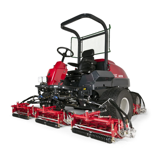
Baroness LM2700 Owner's Operating Manual
5-unit fairway mower
Hide thumbs
Also See for LM2700:
- Service manual (325 pages) ,
- Owner's operating manual (60 pages) ,
- Operator's manual (44 pages)

Subscribe to Our Youtube Channel
Related Manuals for Baroness LM2700


Summary of Contents for Baroness LM2700
- Page 1 Owner's Operating Manual 5-Unit Fairway Mower Required reading Read this manual and the Owner's Manual for the engine before using the machine. Serial No.11001- Ver.3.0...
-
Page 2: Table Of Contents
Contents Greeting ........................1 Inspection before use ..............15 Caution Keeping the owner's operating manual ..............1 5- 1 Cleaning of the radiator and oil cooler ........15 Caution California proposition 65 ..................1 5- 2 Inspection of the radiator and coolant level ......16 Caution 5- 3 Inspection and refilling of engine oil ............ - Page 3 7-16 Reel reverse rotation switch ............. 26 12- 4 Backlapping .............. 38 Caution Danger Caution 7-17 Throttle lever ................... 26 12- 5 Adjustment of the groomer (option) ........39 Caution 7-18 Mower unit raise/lower lever ............. 27 12- 6 Adjustment of the reel cover ..............39 Caution 7-19 Bypass valve ...................
-
Page 4: Greeting
When replacing parts, be sure to use genuine Baroness parts or parts designated by Kyoeisha. Note that the Baroness product warranty may not apply to defects caused by the use of California proposition 65 parts from other companies. -
Page 5: Warning Symbols
Warning symbols Purpose This manual uses the following warning symbols for handling precautions that are important This machine is intended for cutting turf grass at golf courses. for your safety. Do not use this machine in any way other than its intended purpose, and do not modify the machine. -
Page 6: Warning Preparation
−3− [2]Control of a ride-on machine sliding on a slope will not be regained by the application 5.Check that operator's presence controls, safety switches and shields are attached and of the brake. functioning properly. Do not operate unless they are functioning properly. The main reasons for loss of control are 6.If the brake operation is faulty or the parking brake lever has noticeable play, be sure to adjust or repair them before operating the machine. -
Page 7: Maintenance And Storage
Maintenance and storage 8.Disengage the drive to attachments, stop the engine, and remove the ignition key in the following conditions. 1.Disengage drives on level ground, lower the attachments, set parking brake, stop engine [1]Before refueling. and remove key from ignition. Wait for all movement to stop before adjusting, cleaning or [2]Before removing the grass catcher/catchers. -
Page 8: About The Waste Disposal
−5− About the waste disposal [2]Be careful durig adjustment of the machine to prevent entrapment of the fingers between moving blades and fixed parts of the machine. Make sure that waste generated when servicing or repairing the machine is disposed of in 20.On multi-cylinder/multi-reel machines take care as rotating one cylinder/reel can cause accordance with local regulations. -
Page 9: Precautions For Safe Operation
1. Precautions for safe operation seat and check your surroundings for safety. When starting the engine, be sure to be seated in the operator's seat, check the position of the seat, and check your surroundings for safety. Failure to follow this precaution can cause an unexpected accident. 1-1 General precautions ■... -
Page 10: Danger
−7− ● Remove obstacles such as rocks before using machine, they cause the damage of Warning reel cutter and bed knife, and fry apart to invite an accident. In case the obstacles get caught in the reel cutter, switch the engine off, and remove it after stopping the driving unit completely. -
Page 11: Warning When Transporting The Machine
■ Remove debris from the muffler and engine. and chock the wheels. The running board should be non-skid and bear sufficient strength, length, and width. Check that there is no grass, debris, or fuel around the muffler and engine or on the brakes every day before operating the machine. -
Page 12: Warning When Operating The Machine
−9− running board. Use non-skid running board bearing sufficient strength, length, and width. Failure to follow this precaution can cause the machine to overturn or fall, causing damage to the machine. Failure to follow this precaution can cause the machine to have an accident by slipping or overturning. -
Page 13: Danger
● Inspect the rotation speed of engine at the dealer of Baroness to make sure the safety Failure to follow this precaution can cause the machine to overturn and cause an and accuracy of engine. -
Page 14: Specifications
■ Sound Pressure Level This machine was confirmed to have a continuous A-weighted sound pressure level of 88dB by measuring identical machines in accordance with the procedure specified in ISO 5395-1:2013. Model LM2700 ■ Sound Power Level Mower unit type 26in 22in... -
Page 15: Names Of Various Sections
3. Names of various sections Roof Seat Throttle lever Tilt lever Mower unit raise/ Parking brake lever lower lever Radiator Brake pedal Operation panel Hood Oil cooler Fuel filler hole Forward pedal Oil level gauge Reverse pedal Light Muffler exhaust port Mower unit #2 Number plate Mower unit #4... -
Page 16: Warning Label And Operation Label
K4205001950 K4205001530 K4205001580 * Attach on the left and right. <Arm lock part of both side> <Front right of the frame> <Rear right of the frame> LM2700-0959Z0 K4205001940 K4205001580 K4209000980 * Put it on both side. K4209001000 K 4 2 0 5 0 0 1 9 0 0... -
Page 17: Description
Placing your hand near the fan and the belt while the engine is running could result in injury. K4205001530 : Hot surface Caution Do not touch. It can cause burns. LM2700-0959Z0 K4205001540 : Read the Operator's manual. Warning : Pinch Caution... -
Page 18: Caution Inspection Before Use
−15− 5. Inspection before use *1 Number Plate ● Please be sure to check the following matter before putting the Caution engine into operation. 5-1 Cleaning of the radiator and oil cooler *2 ROPS authentication decal Be sure to clean when the dust has adhered to the radiator, oil cooler, and dustproof net. When you operate it in the dusty place, please try to clean a little early Oil cooler Radiator... -
Page 19: Caution Inspection Of The Radiator And Coolant Level
5-3 Inspection and refilling of engine oil 5-2 Inspection of the radiator and coolant level ● Perform the inspection when the engine is cold. The radiator cap Caution is the pressure type. If the radiator cap is removed when the Put the engine on the level surface, and engine is high temperature, the steam blows off and it may Oil level dipstick... -
Page 20: Inspection Of The Hydraulic Oil
−17− 5-4 Inspection of the hydraulic oil 5-6 Inspection of the engine and its surroundings Level the engine and always check whether Please refer to "Operating and instruction manual" for engine for Oil level gauge the hydraulic oil is contained to the center of handling of the engine. -
Page 21: Danger
5-9 Supply of fuel 5-10 Inspection of battery Refer to the Battery's instruction manual. Stay the machine on the level. Fuel guage approaches E (Empty), supply The machine exported from Japan mounts fuel (diesel) immediately. the battery of refillable type. (FX105D31R) Over-supply of the fuel is possible to cause the overflow of fuel from the fuel cap, when Inspect and maintenance the battery... -
Page 22: Fastening Of Each Portion
−19− 6. Fastening of each portion Important A number of bolts are used in each part of this machine. be sure to re-tighten the bolts and nuts, because they may be loosened at the earlier stage of the use. 6-1 Tightening torque As to the bolts and nuts without any special instruction, tighten them in appropriate tightening torque with proper tool. -
Page 23: Tightening Torque By Model
6-2 Tightening torque by model LM2700 Tighten the following bolts and nuts at the torque specified in the table. For thread locking adhesive, apply a middle strength thread locker (ThreeBond 1322 or equivalent anaerobic sealant). Tightening torque Thread locking Location... -
Page 24: Operation Method Of Each Part
−21− 7. Operation method of each part Switch and levers on the operation panel Switch and levers on the operation panel a. Travelling –Mowing changeover switch a. Travelling –Mowing changeover switch e. Pilot lamp e. Pilot lamp b. 2WD-4WD changeover switch b. -
Page 25: Caution Starting And Stopping The Engine
7-3 Starting and stopping the engine ● Stopping procedure 1) Hold the brake pedal down, pull the parking brake lever up until it engages. 2) Make the reel rotary switch into the "OFF" position. ● Pay attention if you put the key switch ON position, when the Caution 3) Return the throttle lever to the "LOW"... -
Page 26: Caution Cautions When Leaving The Machine
−23− When mowing Conditions to function the interlock system. 1) Operator sits on the seat. Reel Travelling- Reel 2) Travelling-Mowing changeover switch is "Mowing" position. Parking Reverse Travelling Mowing Seat Rotating Brake Rotation Pedals Changeover 3) Reel rotation switch is "ON" position. Switch Switch Switch... -
Page 27: Brake Pedal
7-6 Brake pedal 7-9 Speed limiter lever As you press the brake pedal, brake It is a shift lever, which restricts the forward functions. pedal step in amount. The step in amount When it does not function well, adjust or decreases if it turns to the "SLOW"... -
Page 28: Caution Tilt Steering
−25− 7-11 Tilt steering 7-13 Travelling-mowing changeover switch Pull lever up to release steering column. When it is set to UP, the position of mower Steering unit #4 & #5 can be changed. Tilt column up or down to position desired. -
Page 29: Caution 2Wd - 4Wd Changeover Switch
7-14 2WD - 4WD changeover switch 7-16 Reel reverse rotation switch It is the switch that chooses two-wheeldrive Locates inside the hood. (front wheel) travelling or four-wheel drive It is the rocker switch that exchange the travelling. If it moves to the "2WD" position it rotation direction of the reel. -
Page 30: Mower Unit Raise/Lower Lever
−27− 7-18 Mower unit raise/lower lever 7-20 Reel rotation adjusting valve <For mower units #1, #4 and #5> <For mower units #2 and #3> It is the shifter lever that raises or lowers the Neutral mower unit. position DOWN If the shifter lever is moved to the "UP" (Operation) position, the mower unit will go up, and if it is moved to the "DOWN"... -
Page 31: Mower Lock Lever (Latch)
8. Measuring instrument 7-21 Mower lock lever (latch) Hang the mower lock lever, when you Mower lock lever 8-1 Instruments of operation panel transfer the machine or store the machine with the mower unit #4 and #5 are raised. a. Tachometer & hour meter b. -
Page 32: Fuel Gauge
−29− 8-4 Fuel gauge 8-7 Oil pressure lamp (engine oil pressure lamp) It indicates current fuel level. If the fuel The lamp turns on when the ignition switch Engine oil pressure lamp gauge approaches E(Empty), supply fuel is in the "ON" position. (diesel) immediately. -
Page 33: Mowing Operation
11. Inspection and maintenance of each section (main unit) 9. Mowing operation 11-1 Change of engine oil 1) Open the hood and reel-reverse-rotation switch to “OFF”.(Refer to 7-16 ) 2) Start the engine. Refer to the engine's instruction manual for handling of the engine. 3) Pull up the throttle lever and set engine speed to MAX (2,600rpm). -
Page 34: Change Of Hydraulic Oil
−31− 11-2 Change of hydraulic oil 11-4 Greasing Since there may be adhesion or damage due to lack of grease on moving parts, they must 1) Change the hydraulic oil after the first be greased. 100-hour operation, and change it in the shorter period between the one year and Add urea-based No. -
Page 35: Replacement Of Fuses
Greasing Points 11-5 Replacement of fuses ● When performing maintenance on the electrical system, be sure Warning to remove the negative battery wire. ● If a fuse blows, a short may have occurred within the electrical Caution circuit. Check for the cause, such as faulty terminal connections, damaged wiring or terminals, or incorrect wiring. -
Page 36: Opening And Closing The Engine Hood
−33− 11-6 Opening and closing the engine hood 11-8 Adjustment of brake Disconnect the rubber catch in right and left, Rubber catch ● Make sure that the brake wire is not cracked or damaged. Danger and pull up the engine hood upwards until the wire stretches to the limit. -
Page 37: Air-Bleeding From Fuel
2) Reduce the clearance by loosening the 10) If the left and right brakes are not equally Brake disc Wire lock nut, then tightening the adjustment effective, make fine adjustments with the nut. adjustment bolt on the brake disc side. Adjustment bolt Adjustment nut (on brake disc side) -
Page 38: Jacking Up The Machine
−35− 11-10 Jacking up the machine 1) Front right frame ● When replacing a tire or beginning any other maintenance or Warning repairs, be sure to chock the wheels to prevent the machine from moving. ● Before jacking up the machine, park it on a hard, flat surface such as a concrete floor and remove any obstacles that could prevent you from performing the work safely. -
Page 39: Inspection And Maintenance Of Each Section (Mower)
12. Inspection and maintenance of each section (mower) 4) Rear frame 12-1 Greasing Carry out the greasing up periodically to each part grease fitting. The parts greasing up every 10 hours is using the needle bearing. Be careful of the lubrication interval. -
Page 40: Cutting Height Adjustment
−37− 12-2 Cutting height adjustment 2) Adjust the height of the rear roller. ● To avoid personal injury and damage by the cutting edges wear groves and handle the (1) As shown in the figure, apply the screw reel and bedknife with extreme care. "a"... -
Page 41: Adjusting The Blades
12-3 Adjusting the blades 12-4 Backlapping Proper reel-to-bedknife adjustment is critical. 1) Inspect whether the newspaper can cleanly cut across the full length of reel. 2) Set the bypass valve lever of the hydraulic motor into the "Rotation" position on the ●... -
Page 42: Adjustment Of The Groomer (Option)
−39− 12-5 Adjustment of the groomer (option) 12-6 Adjustment of the reel cover 1) S e t t h e s m a l l a d j u s t i n g s c r e w f o r ●... -
Page 43: Danger
12-8 Turning the #2 and #3 mower units 4) Raise the mower unit. It is easily maintainable, to turn the #2 and #3 mower unit turn to outside of the main Lock pin body. 1) Lower the mower unit, and remove the Retaining pin, and then pull out the Lock pin. -
Page 44: Cautions For Maintenance
● Use correct/appropriate parts in good condition. Inspection of fan belt ● Repair or replace worn or damaged parts immediately. ● Do not modify any mechanical equipments/parts. Use Baroness Inspection of battery electrolyte genuine parts required for maintenance for safety. -
Page 45: Adjustment Of The Other Functions
14. Adjustment of the other functions <Specifications for periodic maintenance> Engine oil capacity MAX: 9.7 L MIN: 7 L Higher than the API service classification CD class 14-1 Adjustment of the neutral position of piston pump Coolant capacity Total capacity 12 L Including 1 L in reserve tank Tire pressure (standard tire) Front tire 150 kPa... - Page 46 1-26, Miyuki-cho, Toyokawa, Tel : (0533)84-1390 Head Office Aichi-Pref. 442-8530 Japan. Fax : (0533)89-3623 LM2700--UM--USZ/17D-00-SPEC...
Need help?
Do you have a question about the LM2700 and is the answer not in the manual?
Questions and answers