Advertisement
Table of Contents
Advertisement
Table of Contents

Related Manuals for Abilica Abilica Spin


Summary of Contents for Abilica Abilica Spin
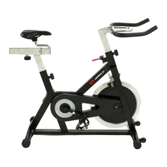
- Page 1 Assembly- and user’s manual for Abilica Spin Art. No: 555 046...
- Page 2 COMPLETE PARTS-DRAWING...
- Page 3 COMPLETE PARTS LIST NAME QUANTITY REMARK RIGHT PEDAL (R) END CAP 1 CARRIAGE BOLT (M8*70) REAR STABILIZER CURVED WASHER (Ø 8) DOMED NUT SPRING ADJUSTMENT KNOB INSERT PLASTIC LEFT PEDAL (L) VERTICAL SEAT POST END CAP 2 SEAT POST SEAT END CAP 3 FRONT STABILIZER MAIN FRAME...
- Page 4 ASSEMBLY FIG.1 FIG.1: Remove the bolts and nut from the bottom tube, then attach the Front Stabilizer (pt.15) to the Main Frame (pt.16) using two sets of Ø8 Curved Washers (pt.5), M8 Domed Nut (pt.6) and M8*70 Carriage bolt (3). Attach the Rear Stabilizer (pt.4) to the Main Frame (pt.16) using two sets of Ø8 Curved Washers (pt.5), M8 Domed...
- Page 5 FIG.3 FIG.3: Slide the Handlebar Post (pt.17) into the handlebar post housing on the main frame. You will have to slacken the knurled section Spring Adjustment Knob (pt.7) and pull the knob back and then select and align holes for the desired height. Release the knob and retighten the knurled portion.
- Page 6 A low resistance makes it easier to pedal, and is acheived by turning the tension knob counterclockwise. Supplier: Sport Supply Int. AS PO Box 244 N-3051 Mjøndalen Norway E-mail: post@sportsupply.no www.abilica.com www.sportsupply.no © Sport Supply Int. AS...
Need help?
Do you have a question about the Abilica Spin and is the answer not in the manual?
Questions and answers