Advertisement
Advertisement
Table of Contents

Related Manuals for Abilica Spinoff


Summary of Contents for Abilica Spinoff
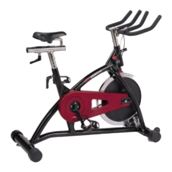
- Page 1 ABILICA SPINOFF Art. 554 060 English User Manual...
- Page 2 * IMPORTANT SAFETY INFORMATIONS * Please follow the safety rules below to avoid injury and/or accidents. You may stop the bike immediately by controlling emergency break on the left side of handlebar. Keep the bike away from the reach of children. Do not allow the children to be stay around when using the machine.
-
Page 3: Operating Instructions
* OPERATING INSTRUCTIONS RESISTANCE ADJUSTMENT: Pedaling resistance is controlled by the tension knob locate under the handlebar right side. To increase resistance, turn the tension knob clockwise. To decrease resistance, turn the tension knob counter clockwise. SEAT ADJUSTMENT: Properly adjust the seat to ensure maximum exercise efficiency and comfort, while help reducing the risk of injury. The most appropriate seat position to bikes when place one pedal in the downward position. - Page 4 Warming up: Following exercises are light but appropriate movements, which will wake up your body, stimulate your circulation and make your ankles more flexible. Please do these warming up exercises more than once before starting your training. 1. Calf: 2. Knee: Lean against the wall with both hands.
-
Page 5: Exploded View
EXPLODED VIEW... -
Page 6: Parts And Tools List
PARTS AND TOOLS LIST PART# DESCRIPTION Q'TY PART# DESCRIPTION Q'TY Main frame Bushing 50.1L Front stabilizer Tension adjuster Rear stabilizer Handlebar Seat Fixing knob M16 Seat post Washer M6*13*2T BK Handlebar post Chain adjustable screw M6*57L Flywheel Nylon nut M6 BK End cap φ3"... -
Page 7: Assembly Instructions
ASSEMBLY INSTRUCTIONS Step 1 Install front stabilizer (2) to main frame (1), using bolts (54) and washers (53). Step 2 Install rear stabilizer (3) to main frame (1), using bolts (54) and washers (53). - Page 8 Step 3 Using bolt (61) and washer (60) to fix handlebar(36) on handlebar post. Then slide emergency brake (58) onto handlebar left side, fix bolt (59). Step 4 Slide the seat post (5) into the main frame (1) and tighten the plastic adjustable knob (37) Open sensor cable (65) to clip on handlebar right side and fix it by screw (66) and nut (67).
- Page 9 Step 5 Securely fix the seat (4) to the seat bar (26). Slide the seat bar into seat post (5) and tighten adjustable knob. Step 6 Firmly screw each pedal (30) (21) into crank arms.
- Page 10 COMPUTER OPERATION INSTRUCTIONS AS-8 1. ACCESSORIES UNIT Q’TY PART NAME INCLUDINGS 1 CYLCE COMPUTER LR44 BATTERY BRACKET SENSOR CABLE, SCREW NUT MAGNET MAGNET, SCREW CABLE TIE RUBBER PAD 2. FEATURE AND FUNCTION AS-6/6G AS-8/8G AS-11/11G AS-506 AS-904 FEATURE AND FUNCTION SYMBOL SPECIFICATION AS-828/248...
-
Page 11: Operation
AS-6/6G AS-8/8G AS-11/11G AS-506 AS-904 FEATURE AND FUNCTION SYMBOL SPECIFICATION AS-828/248 AS-710 AS-826/246 AS-904G AS-818/508 AS-511 AS-900/900G ● STOP WATCH STOP WATCH 0.01SEC-9 59.59 ● ● ● ● SCAN SCAN ● ● ● ● START/STOP AUTOMATTICALLY ● ● ● ● POWER ON/OFF AUTOMATICALLY SENSOR:NO CONTACT MAGNETIC SENSOR BATTERY TYPE:LR44, AG13... -
Page 12: Troubles Shooting
Don’t use thinner, alcohol or benzene to clean! BICYCLE WHEEL SIZE INCH VS. CM INCH INCH EXAMPLE: 8”(INCH) = 8 X 2.54 X 3.1416 = 64CM Leverandør: Sport Supply Int. AS Postboks 226, 3051 Mjøndalen E-post: post@sportsupply.no200 www.abilica.no © Sport Supply Int. AS...
Need help?
Do you have a question about the Spinoff and is the answer not in the manual?
Questions and answers