Table of Contents
Advertisement
Quick Links
Advertisement
Table of Contents

Related Manuals for Kyocera PF-430


Summary of Contents for Kyocera PF-430
- Page 1 PF-430 SERVICE MANUAL Published in January 2006 845H2110 5H2SM060 First Edition...
- Page 2 Revision history Revision Date Replaced pages Remarks...
-
Page 3: Safety Precautions
Safety precautions This booklet provides safety warnings and precautions for our service personnel to ensure the safety of their customers, their machines as well as themselves during maintenance activities. Service personnel are advised to read this booklet carefully to familiarize themselves with the warnings and precautions described here before engaging in maintenance activities. - Page 4 Safety warnings and precautions Various symbols are used to protect our service personnel and customers from physical danger and to prevent damage to their property. These symbols are described below: DANGER: High risk of serious bodily injury or death may result from insufficient attention to or incorrect compliance with warning messages using this symbol.
- Page 5 1.Installation Precautions WARNING • Do not use a power supply with a voltage other than that specified. Avoid multiple connections to one outlet: they may cause fire or electric shock. When using an extension cable, always check that it is adequate for the rated current....................•...
-
Page 6: Specifications 1
2.Precautions for Maintenance WARNING • Always remove the power plug from the wall outlet before starting machine disassembly....• Always follow the procedures for maintenance described in the service manual and other related brochures............................• Under no circumstances attempt to bypass or disable safety features including safety mechanisms and protective circuits. - Page 7 • Do not remove the ozone filter, if any, from the copier except for routine replacement..... • Do not pull on the AC power cord or connector wires on high-voltage components when removing them; always hold the plug itself...................... •...
- Page 8 This page is intentionally left blank.
-
Page 9: Table Of Contents
CONTENTS 1-1 Specifications 1-1-1 Specifications............................1-1-1 1-1-2 Parts names............................1-1-2 1-1-3 Machine cross section ..........................1-1-3 1-2 Installation 1-2-1 Unpacking and installation ........................1-2-1 (1) Installation procedure ........................1-2-1 1-3 Troubleshooting 1-3-1 Paper misfeed detection .........................1-3-1 (1) Paper misfeed indication ........................1-3-1 1-3-2 Self-diagnosis ............................1-3-2 (1) Self-diagnostic function ........................1-3-2 1-3-3 Electric problems ............................1-3-3 (1) Defective paper jam detecting. - Page 10 This page is intentionally left blank.
-
Page 11: Specifications
1-1 Specifications 1-1-1 Specifications Model name ........Paper feeder Paper size........Envelope C5, Envelope C4, Executive, A3, B4, A4, A4R, B5R, ISO-B5, A5R, Ledger, Legal, Letter, Letter-R, Folio, Oficio II, 8K, 16K, Custom (148 to 210 × 297 to 432 mm) Paper capacity ........ -
Page 12: Parts Names
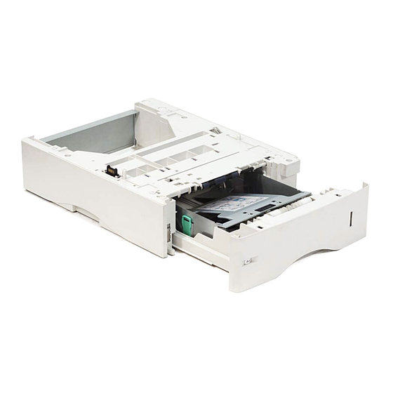
1-1-2 Parts names Figure 1-1-1 Paper cassette Paper size window Paper gauge Interface connector Pins 1-1-2... -
Page 13: Machine Cross Section
1-1-3 Machine cross section Paper path Figure 1-1-2Machine cross section 1-1-3... - Page 14 This page is intentionally left blank. 1-1-4...
-
Page 15: Installation
1-2 Installation 1-2-1 Unpacking and installation (1) Installation procedure Installing the paper feeder 1. Remove the paper feeder from the container box and place the feeder where you want to install it. 2. Lift the printer up without tilting it, then put it down onto the paper feeder(s) by fitting the four corners as shown in the figure. - Page 16 4. Remove the cassette cover. Cassette cover 5. Push the bottom plate down until it locks. Bottom plate Figure 1-2-3 Paper size window 6. Turn the paper size dial so that the size of the paper you are going to use appears in the paper size window.
- Page 17 8. If using A3 or Ledger paper, pull out the extension paper cassettes pushing the lock A3, Ledger, B4, Legal lever one by one and adjust them to the A4, Letter, B5 desired paper size. Extension cassette Lock lever Lock lever Figure 1-2-7 9.
- Page 18 11. Slide the paper into the paper cassette. Paper Paper cassette Figure 1-2-10 12. Insert the paper cassette into the slot in the paper feeder. Push it straight in as far as it will go. Cassette cover Paper cassette Figure 1-2-11 Completion of the machine installation.
-
Page 19: Paper Misfeed Detection
1-3 Troubleshooting 1-3-1 Paper misfeed detection (1) Paper misfeed indication When a paper misfeed occurs, the printer immediately stops copying and displays the jam location on the printer operation panel. Paper jam Paper misfeed message Cassette 2 Paper misfeed location Figure 1-3-1 (Cassette 1) (Printer) -
Page 20: Self-Diagnosis
1-3-2 Self-diagnosis (1) Self-diagnostic function This printer is equipped with self-diagnostic function. When a problem is detected, the printer stops printing and display an error message on the operation panel. An error message consists of a message prompting a contact to service personnel, total print count, and a four-digit error code indicating the type of the error. -
Page 21: Electric Problems
1-3-3 Electric problems Problem Causes Check procedures/corrective measures Actuators of paper feed Repair or replace. (1) Defective paper sensor does not operate jam detecting. False smoothly. paper jam message display. A piece of paper torn from a Check visually and remove it, if any. sheet is caught around actuator of paper feed sen- sor. -
Page 22: Mechanical Problems
1-3-4 Mechanical problems Problem Causes/check procedures Corrective measures Check if the surfaces of the following rollers Clean with isopropyl alcohol. (1) No paper feed. are dirty with paper powder: Pickup roller, Paper feed roller Check if the pickup roller and paper feed roller Check visually and replace any deformed are deformed. -
Page 23: Assembly And Disassembly
1-4 Assembly and Disassembly 1-4-1 Precautions for assembly and disassembly (1) Precautions Be sure to turn the power switch off and disconnect the power plug before starting disassembly. When handling PWBs, do not touch connectors with bare hands or damage the board. Do not touch any PWB containing ICs with bare hands or any object prone to static charge. -
Page 24: Assembly And Disassembly
1-4-2 Assembly and disassembly (1) Removing the conveying roller, paper feed roller and pickup roller 1. Remove the paper cassette from the paper feeder. 2. Remove the two stoppers 3. Remove the two bushes and then remove the middle roller. 4. -
Page 25: Removing The Retard Roller
(2) Removing the retard roller 1. Remove the paper cassette from the paper Bottom plate feeder. 2. Push the bottom plate down until it locks. Paper cassette 3. Remove the retard guide. Retard guide Figure 1-4-2 4. Remove the retard holder (roller) from the retard guide. -
Page 26: Remove The Drive Unit And Main Pwb
(3) Remove the drive unit and main PWB 1. Remove the four screws. 2. Pull the upper cover rear ends (1). Screw 3. While pulling out the cassette size switch Screw (2), and then remove the upper cover. Upper cover Screw Screw Cassette size... - Page 27 6. Remove the three screws and then detach the PWB bracket. PWB bracket Screw Screw Screw Figure 1-4-6 7. Remove the two connectors (A). 8. Remove the one clamp. 9. Remove the three connectors (B). 10. Remove the two screws and then remove the main PWB.
- Page 28 This page is intentionally left blank. 1-4-6...
-
Page 29: Paper Feed Section
2-1 Mechanical construction 2-1-1 Paper feed section (1) Paper feed section The paper feeder conveys paper from the paper cassette to the printer. Paper cassette can hold up to 250 sheets of paper. Paper is fed from the paper feeder by the rotation of the pickup roller and paper feed roller. The retard roller prevents mul- tiple sheets from being fed at one time, via the torque limiter. - Page 30 This page is intentionally left blank. 2-1-2...
-
Page 31: Electrical Parts Layout
2-2 Electrical Parts Layout 2-2-1 Electrical parts layout (1) Electrical parts Electrical parts Figure 2-2-1 Main PWB ............ Controls electrical components in the paper feeder and communications with the printer. Paper feed sensor........Detects paper jam in the paper feeder. Paper gauge sensor 1........ - Page 32 This page is intentionally left blank. 2-2-2...
-
Page 33: Main Pwb
2-3 Operation of the PWBs 2-3-1 Main PWB Main PWB +24V DC24V, DC5V PFM_A OPSDI, OPSDO M_SM1 PFM_*A Printer/ PFM_B Upper OPSCLK M_SM2 Motor Paper PFM_*B paper driver IC OPRDYN feed M_REF feeder (IC4) motor OPSEL0, OPSEL1, OPSEL2 ENABLE +24V1 Paper Driver feed... - Page 34 Figure 2-3-2Main PWB silk-screen diagram Connector Pin No. Signal Voltage Description +24V 0/24 V DC Paper feed clutch: On/Off Connected Ground to the paper feed clutch SCLK 0/5 V DC (pulse) Serial communication clock signal Connected 0/5 V DC (pulse) Serial communication data signal to the 0/5 V DC (pulse)
- Page 35 2-4 Appendixes 2-4-1 Wiring diagram 2-4-1...
- Page 36 This page is intentionally left blank. 2-4-2...
Need help?
Do you have a question about the PF-430 and is the answer not in the manual?
Questions and answers