Table of Contents
Advertisement
Quick Links
Advertisement
Table of Contents

Subscribe to Our Youtube Channel
Related Manuals for Kyocera PF-770


Summary of Contents for Kyocera PF-770
- Page 1 PF-770 SERVICE MANUAL Published in April 2011 3NGSM061 Rev.1...
- Page 2 CAUTION RISK OF EXPLOSION IF BATTERY IS REPLACED BY AN INCORRECT TYPE. DISPOSE OF USED BATTERIES ACCORDING TO THE INSTRUCTIONS. It may be illegal to dispose of this battery into the municipal waste stream. Check with your local solid waste officials for details in your area for proper disposal. ATTENTION IL Y A UN RISQUE D’EXPLOSION SI LA BATTERIE EST REMPLACEE PAR UN MODELE DE TYPE INCORRECT.
-
Page 3: Revision History
Revision history Revision Date Replaced pages Remarks 6 April 2011 CONTENTS, 2-4-1 to 2-4-3... - Page 4 This page is intentionally left blank.
-
Page 5: Safety Precautions
Safety precautions This booklet provides safety warnings and precautions for our service personnel to ensure the safety of their customers, their machines as well as themselves during maintenance activities. Service personnel are advised to read this booklet carefully to familiarize themselves with the warnings and precautions described here before engaging in maintenance activities. -
Page 6: Safety Warnings And Precautions
Safety warnings and precautions Various symbols are used to protect our service personnel and customers from physical danger and to prevent damage to their property. These symbols are described below: DANGER: High risk of serious bodily injury or death may result from insufficient attention to or incorrect compliance with warning messages using this symbol. -
Page 7: Installation Precautions
1. Installation Precautions WARNING • Do not use a power supply with a voltage other than that specified. Avoid multiple connections to one outlet: they may cause fire or electric shock. When using an extension cable, always check that it is adequate for the rated current...................... •... - Page 8 2. Precautions for Maintenance WARNING • Always remove the power plug from the wall outlet before starting machine disassembly....• Always follow the procedures for maintenance described in the service manual and other related brochures............................• Under no circumstances attempt to bypass or disable safety features including safety mechanisms and protective circuits.
- Page 9 • Do not remove the ozone filter, if any, from the copier except for routine replacement....... • Do not pull on the AC power cord or connector wires on high-voltage components when removing them; always hold the plug itself......................•...
- Page 10 This page is intentionally left blank.
-
Page 11: Table Of Contents
3NG-1 CONTENTS 1-1 Specifications 1-1-1 Specifications ........................1-1-1 1-1-2 Parts names .......................... 1-1-2 1-1-3 Machine cross section ......................1-1-3 1-2 Installation 1-2-1 Installation environment......................1-2-1 1-2-2 Unpacking..........................1-2-2 (1) Unpacking......................... 1-2-2 (2) Remove the tapes and pad ....................1-2-3 1-2-3 Installing the SD cassette heater (Option) ................1-2-5 1-3 Maintenance Mode 1-3-1 Maintenance mode ........................ -
Page 12: Operation Of The Pwbs
3NG-1 2-3 Operation of the PWBs 2-3-1 SD main PWB........................2-3-1 2-4 Appendixes 2-4-1 Appendixes ..........................2-4-1 (1) List of maintenance parts ....................2-4-1 (2) Periodic maintenance procedures ..................2-4-2 (3) Wiring diagram ......................... 2-4-3... -
Page 13: Specifications
1-1 Specifications 1-1-1 Specifications Item Specifications Paper weight 60 to 300g/m Paper types Plain (80g/m or less), Thick (256g/m or less), recycled Paper size A4, B5,Letter Paper capacity 3000 sheets (80g/m 321 (W) x 504 (H) x 620 (D) mm Dimensions ”... -
Page 14: Parts Names
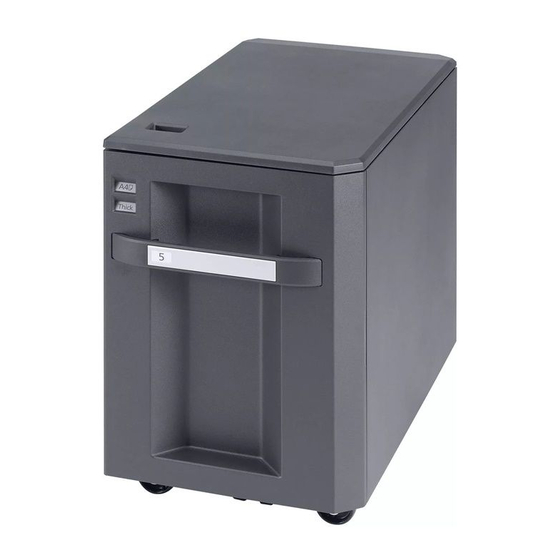
1-1-2 Parts names Figure 1-1-1 1. Front cover 5. SD paper feed unit 2. Lift plate 6. Rear cover 3. Paper width guide front 7. Electrical wire cover 4. Paper width guide rear 8. Left cover 1-1-2... -
Page 15: Machine Cross Section
1-1-3 Machine cross section Paper path Figure 1-1-2 1-1-3... - Page 16 This page is intentionally left blank. 1-1-4...
-
Page 17: Installation Environment
1-2 Installation 1-2-1 Installation environment Installation location (Be based on the machine establishment place.) Avoid direct sunlight or bright lighting. Ensure that the photo conductor will not be exposed to direct sunlight or other strong light when removing paper jams. Avoid locations subject to high temperature and high humidity or low temperature and low humidity;... -
Page 18: Unpacking
1-2-2 Unpacking (1) Unpacking 26 27 14 15 Figure 1-2-1 Unpacking 1. Outer case 12. Accessory pad 23. S tight screw M4 × 8B 2. Inner frame 13. Spacer B 24. Cover plate 3. Bottom pad 14. Plastic bag 25. Spacer A 4. -
Page 19: Remove The Tapes And Pad
(2) Remove the tapes and pad Procedure Tape 1. Remove five tapes. Tape Tape Tape Tape Figure 1-2-2 2. Remove two tapes and remove the con- nector wire. Tape Tape Connector wire Figure 1-2-3 1-2-3... - Page 20 3. Pull the deck forward. Tape 4. Remove four tapes from the pad. Tape 5. Remove the pad from the deck. 6. Gently push the deck back in. Tape Tape Deck Figure 1-2-4 1-2-4...
-
Page 21: Installing The Sd Cassette Heater (Option)
1-2-3 Installing the SD cassette heater (Option) Procedure (Side deck side) Rear cover 1. Remove the connector of the paper feeder on the main body side. 2. Remove four screws and then remove the rear cover. Screw Screw Screw Screw Figure 1-2-5 3. - Page 22 5. Pull the deck forward. Deck Figure 1-2-7 6. Install the SD cassette heater by using two screws on the base. Screw Screw SD cassette heater Figure 1-2-8 1-2-6...
- Page 23 7. Connect the connector of the SD cas- sette heater to the connector of the inlet SD cassette heater electrical wire. 8. Pass through the wire of the SD cas- sette heater to four wire saddles and the edging saddle. 9.
- Page 24 12. Connect the connector of the heater Connector of paper feeder outlet assembly to the connector of the paper feeder. 13. Install the heater outlet assembly by using removed two screws. Screw Connector Screw Heater outlet assembly Figure 1-2-11 14. Connect the side deck and the paper feeder by the AC power code and the connector wire.
-
Page 25: Maintenance Mode
1-3 Maintenance Mode 1-3-1 Maintenance mode The machine is equipped with a maintenance function which can be used to maintain and service the machine. (1) Executing a maintenance item Start Enter “10871087” using Maintenance mode is entered. the numeric keys. Enter the maintenance item The maintenance item is selected. -
Page 26: Maintenance Modes Item List
(2) Maintenance modes item list Section Item Content of maintenance item Initial setting General U000 Outputting an own-status report U001 Exiting the maintenance mode U019 Displaying the ROM version Drive, U034 Adjusting the print start timing paper feed LSU Out Top 0/0/0/0/0/0/0/0/0/0/0/0 and paper LSU Out Left... -
Page 27: Contents Of The Maintenance Mode Items
(3) Contents of the maintenance mode items Item No. Description U000 Outputting an own-status report Description Outputs lists of the current settings of the maintenance items, and paper jam and service call occurrences. Outputs the event log or service status page. Also sends output data to the USB memory. - Page 28 Item No. Description U000 Method: Send to the USB memory 1. Press the power key on the operation panel, and after verifying the main power indicator has gone off, switch off the main power switch. 2. Insert USB memory in USB memory slot. 3.
-
Page 29: Event Log
Item No. Description U000 Event log Event Log 27/Oct/2010 08:40 Firmware version 2LC_2000.000.000 2010.10.27 [XXXXXXXX] [XXXXXXXX] [XXXXXXXX] [XXXXXXXX] (12) Paper Jam Log Counter Log Count. Event Descriprions J0000: J0041: C0000: T00: 9999999 0501.01.08.01.01 J0001: J0042: C0001: T01: 8888888 4002.01.08.01.01 J0002: J0043: C0002: T02:... - Page 30 Item No. Description U000 Detail of event log Items Description Controller BROM version Operation panel mask version Machine serial number Paper Jam Count. Event Remembers 1 to 16 of The total page count Log code (hexadeci- occurrence. If the occur- at the time of the mal, 5 categories) rence of the previous...
- Page 31 Item No. Description U000 Items Description Paper Jam (d) Detail of paper type (Hexadecimal) cont. 01: Plain 0A: Color 15: Custom 1 02: Transparency 0B: Prepunched 16: Custom 2 03: Preprinted 0C: Envelope 17: Custom 3 04: Labels 0D: Cardstock 18: Custom 4 05: Bond 0E: Coated...
- Page 32 Item No. Description U000 Items Description Service Call Count. Service Code Remembers 1 to 8 The total page Self diagnostic error code of occurrence of self count at the time of (See page 1-4-3) diagnostics error. If the self diagnostics the occurrence of error.
- Page 33 Item No. Description U000 Items Description (12) Counter Log (f) Paper jam (g) Self diagnostic (h) Maintenance item error replacing Comprised of Indicates the log Indicates the log Indicates the log coun- three log coun- counter of paper counter of self diag- ter depending on the ters including jams depending on...
-
Page 34: Service Status Page
Item No. Description U000 Service status page (1) Service Status Page 27/10/2010 12:00 Firmware version 2LC_2000.000.000 2010.10.27 [XXXXXXXX] [XXXXXXXX] [XXXXXXXX] Controller Information Memory status Total Size 2.0 GB (32) FRPO Status Default Pattern Switch Time Default Font Number C5*1000+C2*100+C3 00000 Local Time Zone +01:00 Amsterdam Date and Time... - Page 35 Item No. Description U000 Service status page (2) Service Status Page 27/10/2010 12:00 Firmware version 2LC_2000.000.000 2010.10.27 [XXXXXXXX] [XXXXXXXX] [XXXXXXXX] Engine Information Send Information (33) (37) NVRAM Version _1F31225_1F31225 Date and Time 10/10/27 (34) (38) Scanner Version 2LC_1200.001.089 Address (35) FAX Slot1 FAX BOOT Version 2LC_5000.001.001...
- Page 36 Item No. Description U000 Detail of service status page Description Supplement Firmware version System date Engine soft version Engine boot version Operation panel mask version Machine serial number Total memory size Local time zone Report output date Day/Month/Year hour:minute (10) NTP server name (11) Presence or absence of the...
- Page 37 Item No. Description U000 Description Supplement (27) Fax kit information This item is printed only when the fax kit is installed. (28) Number of rings 0 to 15 (29) Number of rings before auto- 0 to 15 matic switching (30) Number of rings before connect- 0 to 15 ing to answering machine...
- Page 38 Item No. Description U000 Description Supplement (43) Life counter (The first line) Machine life/MP tray/Cassette 1/Cassette 2/ Cassette 3/Cassette 4/Duplex (44) Life counter (The second line) Drum unit K/Drum unit C/Drum unit M/Drum unit Y/ Transfer belt unit/Developer unit K/ Developer unit C/Developer unit M/ Developer unit Y/Maintenance kit A/ Maintenance kit B...
- Page 39 Item No. Description U000 Description Supplement (59) Calibration information Black/Cyan/Magenta/Yellow (60) Calibration information (61) Calibration information (62) Calibration information (63) Calibration information (64) Calibration information (65) Calibration information (66) Calibration information (67) Calibration information (68) Calibration information (69) RFID information (70) RFID reader/writer version infor- mation...
- Page 40 Item No. Description U019 Displaying the ROM version Description Displays the part number of the ROM fitted to each PWB. Purpose To check the part number or to decide, if the newest version of ROM is installed. Method 1. Press the start key. The ROM version are displayed. 2.
- Page 41 Item No. Description U019 Display Description Side paper feeder / Side large capacity feeder ROM PF2 Boot Side paper feeder / Side large capacity feeder booting 1000-sheet finisher / 4000-sheet finisher ROM DF Boot 1000-sheet finisher / 4000-sheet finisher booting Punch unit ROM PH Boot Punch unit booting...
- Page 42 Item No. Description U034 Adjusting the print start timing Description Adjusts the leading edge registration or center line. Purpose Make the adjustment if there is a regular error between the leading edges of the copy image and original. Make the adjustment if there is a regular error between the center lines of the copy image and original.
- Page 43 Item No. Description U034 Adjustment: Leading edge registration adjustment 1. Press the system menu key. 2. Press the start key to output a test pattern. 3. Press the system menu key. 4. Select the item to be adjusted. [LSU Out Top] Setting Initial Change in...
- Page 44 Item No. Description U034 [LSU Out Top B/W] [LSU Out Top 3/4] Setting Initial Change in Display Description range setting value per step MPT(L) Paper feed from MP tray -3.0 to 3.0 0.1 mm (when large size paper is used) Cassette(L) Paper feed from cassette -3.0 to 3.0...
- Page 45 Item No. Description U034 Adjustment: Center line adjustment 1. Press the system menu key. 2. Press the start key to output a test pattern. 3. Press the system menu key. 4. Select the item to be adjusted. Setting Initial Change in Display Description range...
- Page 46 Item No. Description U247 Setting the paper feed device Description Turns on motor and clutches of paper feeder device. Purpose To check the operation of motor and clutches of paper feed device. Method 1. Press the start key. 2. Select the paper feed device. Display Description Paper feeder...
- Page 47 Item No. Description U247 Method: [LCF/Side LCF] 1. Press [Motor], [Clutch] or [Solenoid] and select the item. Display Description Motor PF paper feed motor (PFPFM) is turned off PF paper feed motor (PFPFM) is turned on Clutch PF paper conveying clutch 1 (PFPCCL1) is turned on PF paper conveying clutch 2 (PFPCCL2) is turned on V Feed PF paper conveying clutch 3 (PFPCCL3) is turned on...
- Page 48 Item No. Description U247 Completion Press the stop key. The screen for selecting a maintenance item No. is displayed. U327 Setting the cassette heater control Description Sets the cassette heater control. Purpose To change the setting according to the machine installation environment. Setting 1.
- Page 49 Item No. Description U341 Specific paper feed location setting for printing function Description Sets a paper feed location specified for printer output (only if a printer kit is installed). Purpose To use a paper feed location only for printer output. A paper feed location specified for printer output cannot be used for copy output.
- Page 50 Item No. Description U901 Checking copy counts by paper feed locations Description Displays or clears paper feed counts by paper feed locations. Purpose To check the time to replace consumable parts. Also to clear the counts after replacing the con- sumable parts.
-
Page 51: Paper Mis Feed Detection
1-4 Troubleshooting 1-4-1 Paper mis feed detection (1) Paper mis feed indication When a paper mis feed occurs, the machine immediately stops printing and displays the paper mis feed mes- sage on the operation panel. To remove paper mis fed in the machine, pull out the cassette, open the paper conveying unit or paper conveying cover. - Page 52 Code Contents Conditions location* 0000 Initial jam The power is turned on when a sensor in the con- veying system is on. 0108 Waiting for option package Option package won’t become ready. to become ready 0505 No paper feed from cas- SMT feed sensor (SMTFS) does not turn on during sette 5 paper feed from cassette 5.
-
Page 53: Self-Diagnostic Function
1-4-2 Self-diagnostic function (1) Self-diagnostic function This machine is equipped with self-diagnostic function. When a problem is detected, the machine stops print- ing and display an error message on the operation panel. An error message consists of a message prompting a contact to service personnel and a four-digit error code indicating the type of the error. - Page 54 Check procedures/ Code Contents Causes corrective measures 1820 Paper feeder communication Improper installa- Follow installation instruction carefully again. error tion paper A communication error from feeder. paper feeder is detected 10 Defective con- Reinsert the connector. Also check for conti- times in succession.
-
Page 55: Electric Problems
1-4-3 Electric problems If the part causing the problem was not supplied, use the unit including the part for replacement. Troubleshooting to each failure must be in the order of the numbered symptoms. Problem Causes Check procedures/corrective measures 1. Defective connector Reinsert the connector. -
Page 56: Mechanical Problems
1-4-4 Mechanical problems If the part causing the problem was not supplied, use the unit including the part for replacement. Problem Causes/check procedures Corrective measures Check if the surfaces of the following Clean with isopropyl alcohol. No paper feed. rollers are dirty with paper powder. SD forwarding pulley SD paper feed pulley SD separation pulley... -
Page 57: Precautions For Assembly And Disassembly
1-5 Assembly and Disassembly 1-5-1 Precautions for assembly and disassembly (1) Precautions Before starting disassembly, press the Power key on the operation panel to off. Make sure that the Power lamp is off before turning off the main power switch. And then unplug the power cable from the wall outlet. When handling PWBs (printed wiring boards), do not touch parts with bare hands. -
Page 58: Paper Feed Section
1-5-2 Paper feed section (1) Detaching and refitting the SD forwarding pulley and SD paper feed pulley. Procedure 1. Remove the screw and then remove the electrical wire cover. Electrical wire cover Screw Figure 1-5-1 2. Remove the connector from the main body. - Page 59 6. Remove two stop rings A from the SD Stop rings A paper feed pulley axis. 7. Remove the stop ring B and then slide Stop ring B the joint. Joint SD paper feed pulley axis Figure 1-5-3 8. Slide the two bearings at the both ends Spring Bearing of the paper feed pulley holder.
- Page 60 10. Remove the stop ring from the paper Stop ring Paper feed pulley axis feed pulley axis. 11. Pull out the paper feed pulley axis and remove the torque limiter, SD paper feed pulley and one way clutch. One way clutch SD paper feed pulley Torque limiter Paper feed pulley holder...
-
Page 61: Detaching And Refitting The Sd Separation Pulley
(2) Detaching and refitting the SD separation pulley. Procedure 1. Remove the SD paper feed unit. Spacer (see 1-5-2) 2. Turn the SD paper feed unit inside out. Stop ring 3. Remove the stop ring from the separa- tion pulley axis. 4. -
Page 62: Pwbs
1-5-3 PWBs (1) Detaching and refitting the SD main PWB. Procedure 1. Remove four screws and then remove Rear cover the rear cover. Screw Screw Screw Screw Figure 1-5-9 2. Remove all connectors from the SD Hooks main PWB. 3. Remove two screws. 4. -
Page 63: Driving Section
1-5-4 Driving section (1) Detaching and refitting the SD paper feed motor. Procedure 1. Remove the screw and then remove the electrical wire cover. Electrical wire cover 2. Remove the connector of the SD paper feed unit from the main body. 3. - Page 64 6. Remove four screws and then remove the SD driving assembly from the main body. SD driving assembly Screw Screw Screw Screw Main body Figure 1-5-13 7. Remove two connectors in clutch side. 8. Remove the electrical wires by releas- ing two hooks from the electrical wire Connectors in clutch side guide.
- Page 65 10. Remove two stop ring A. 11. Remove the SD paper feed clutch by pulling out to this side. 12. Remove the SD paper conveying clutch Stop ring B by pulling out to this side. 13. Remove two stop ring B. SD paper feed clutch Stop ring B Stop ring A...
- Page 66 16. Remove the connector from the SD paper feed motor. 17. Remove three screws and then remove the SD paper feed motor assembly. Screw Screw Screw SD paper feed motor assmbly Connector SD paper feed motor Figure 1-5-17 18. Remove two screws and then remove the SD paper feed motor.
-
Page 67: Detaching And Refitting The Sd Lift Driving Unit
(2) Detaching and refitting the SD lift driving unit. Procedure 1. Remove the rear cover. (see 1-5-6) Connector 2. Remove the connector (YC8). Clamp 3. Remove five clamps and remove the Clamp electrical wires. Electrical wires Clamp Clamp Clamp SD lift motor SD lift motor assembly Figure 1-5-19 4. - Page 68 This page is intentionally left blank. 1-5-12...
-
Page 69: Mechanical Construction
2-1 Mechanical construction 2-1-1 Mechanical construction The side deck (SD) is comprised of the paper elevating mechanism; which is activated by winding up of the lift wire using the SD lift motor (SDLM), SD forwarding roller, SD feed roller, paper feeder which is driven by the SD separation roller, and the paper relaying unit which is driven the SD feed roller. - Page 70 EPSW SDPS YC5-13 U_LIMT_SW SDULS YC5-16 LDPS SDFS YC5-18 FD_SOL_ACT, FD_SOL_KEP SDPFSOL YC5-9,10 PFCL SDPFCL YC15-1 PCCL SDPCCL YC15-3 MC_SW SDCSW YC5-2 FDD_SW SDDSW YC6-18 CW/CCW, RDY,CLK, REM SDPFM YC16-1,2,3,4 SDMPWB OUT2, OUT1 YC8-1,2 SDLM RDEP_SW1 SDPGS1 YC6-3 RDEP_SW2 SDPGS2 YC6-6 L_LIMT_SW SDLLS...
-
Page 71: Electrical Parts Layout
2-2 Electrical Parts Layout 2-2-1 Electrical parts layout (1) PWB and sensors Machine front Machine inside Machine rear Figure 2-2-1 PWB and sensors 1. SD main PWB (SDMPWB) ....Controls electrical parts. 2. SD paper sensor (SDPS)...... Detects the presence of paper in deck. 3. -
Page 72: Motors And Others
(2) Motors and others Machine front Machine inside Machine rear Figure 2-2-2 Motor and others 1. SD paper feed clutch (SDPFCL) ... Primary paper feed from deck. 2. SD paper conveying clutch (SDPCCL) . Regulates drive transmission to SD feed roller. 3. -
Page 73: Sd Main Pwb
2-3 Operation of the PWBs 2-3-1 SD main PWB YC11 Figure 2-3-1 SD main PWB silk-screen diagram 2-3-1... - Page 74 Connector Signal Voltage Description Ground Connected to MC_SW 0/3.3 V DC SDCS: On/Off the SD con- Not used nection 24V1 switch, SD paper feed Not used solenoid, SD Ground paper sensor, RESERVE SD upper limit sensor, SD 24[V] 24 V DC 24 V DC power output to SDPFSOL feed sensor.
- Page 75 Connector Signal Voltage Description FDD_SW 0/3.3 V DC SDDSW: On/Off Not used OUT2 0/24 V DC(pulse) SDLM2 drive control signal Connected to OUT1 0/24 V DC(pulse) SDLM2 drive control signal the SD lift motor. YC11 Ground Connected to Ground the engine 24V2 24 V DC 24 V DC power input from machine...
- Page 76 This page is intentionally left blank. 2-3-4...
-
Page 77: Appendixes
3NG-1 2-4 Appendixes 2-4-1 Appendixes (1) List of maintenance parts Maintenance part name Alternative Part No. part No. Name used in service manual Name used in parts list SD paper feed pulley PULLEY FEED 302K906350 2K906350 SD separation pulley PULLEY RETARD 302K906360 2K906360 SD forwarding pulley... -
Page 78: Periodic Maintenance Procedures
3NG-1 (2) Periodic maintenance procedures Maintenance User Mainte- Section Points and cautions Page part/location call nance * Paper feed SD paper feed pulley Check Check Clean with alcohol or a dry cloth. P.1-5-2 section Clean Replace Replace after feeding 150,000 sheets. -
Page 79: Wiring Diagram
3NG-1 (3) Wiring diagram YC13 ENG_SDO SID_CLK1 ENG_SDI SID_SDO1 ENG_CLK SID_SEL1 ENG_SEL SID_SDI1 ENG_RDY SID_RDY1 ENG_PAU SID_PAU DEC_OPN1 TANDEM_CAS1_OPEN TANDEM_CAS2_OPEN +3.3V2 SIDE_MULTI_OPEN +3.3V4 YC11 24V2 24V2 SDMPWB RDEP_SW1_PW SDPGS1 RDEP_SW1 RDEP_SW2_PW SDPGS2 RDEP_SW2 HT_LIVE SDCH HT_COM L_LIMT_SW_PW L_LIMT_SW SDLLS FDD_SW SDDSW SDCSW MC_SW... - Page 80 2011...
- Page 81 2011...
Need help?
Do you have a question about the PF-770 and is the answer not in the manual?
Questions and answers