Allen-Bradley PowerFlex 525 User Manual
Devicenet adapter catalog number: 25-comm-d
Hide thumbs
Also See for PowerFlex 525:
- User manual ,
- Original instructions manual (48 pages) ,
- Application technique (24 pages)

Related Manuals for Allen-Bradley PowerFlex 525


Summary of Contents for Allen-Bradley PowerFlex 525
- Page 1 Aotewell Ltd www.aotewell.com Industry Automation User Manual PowerFlex 525 DeviceNet Adapter Catalog Number: 25-COMM-D HongKong|UK|China sales@aotewell.com +86-755-8660-6182...
-
Page 2: Important User Information
Identifies information that is critical for successful application and understanding of the product. Allen-Bradley, Rockwell Automation, Rockwell Software, PowerFlex, Studio 5000 and Connected Components Workbench are trademarks of Rockwell Automation, Inc. Trademarks not belonging to Rockwell Automation are property of their respective companies. -
Page 3: Table Of Contents
Aotewell Ltd www.aotewell.com Industry Automation Table of Contents Important User Information ........2 Preface Overview Recommended Documentation . - Page 4 Aotewell Ltd www.aotewell.com Industry Automation Table of Contents Understanding the I/O Image ........48 Using Logic Command/Status .
- Page 5 Logic Status Word ..........128 PowerFlex 525 Drives...
- Page 6 Aotewell Ltd www.aotewell.com Industry Automation Table of Contents Notes: Rockwell Automation Publication 520COM-UM002A-EN-E - April 2013 HongKong|UK|China sales@aotewell.com +86-755-8660-6182...
-
Page 7: Preface
DNET-UM004 DeviceNet Media Design Installation Guide DNET-UM072 DeviceNet Starter Kit User Manual DNET-UM003 PowerFlex®520-Series Drives PowerFlex 525 Adjustable Frequency AC Drive User Manual 520-UM001 RSLinx® Classic RSLinx Classic Getting Results Guide LINX-GR001 RSNetWorx for DeviceNet Getting Results with RSNetWorx for DeviceNet DNET-GR001 RSLogix™... - Page 8 Aotewell Ltd www.aotewell.com Industry Automation Preface Overview • RSLinx Classic (version 2.51), RSNetWorx for DeviceNet (version 21), and RSLogix 5000 (version 20) were used for the screen captures in this manual. Different versions of the software may differ in appearance and procedures.
-
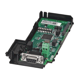
Page 9: Components
Industry Automation Chapter Getting Started The DeviceNet adapter is a communication option intended for installation into a PowerFlex 525 drive. The Multi-Drive feature (Chapter 7) also provides a means for other supported PowerFlex drives and DSI Hosts to connect to a DeviceNet network. -
Page 10: Features
Getting Started Features The features of the DeviceNet adapter include: • Mounting onto a PowerFlex 525 Control Module back cover for installation into the drive. It receives the required power from the drive and from the DeviceNet network. • Switches to set a node address and network data rate before applying power to the PowerFlex drive. -
Page 11: Compatible Products
Parameters icon in the tool bar. Compatible Products At the time of publication, the DeviceNet adapter is compatible with Allen- Bradley PowerFlex 525 drives. Required Equipment Equipment Shipped with the Drive When you unpack the adapter, verify that the package includes:... -
Page 12: Safety Precautions
Aotewell Ltd www.aotewell.com Industry Automation Chapter 1 Getting Started Safety Precautions Please read the following safety precautions carefully. ATTENTION: Risk of injury or death exists. The PowerFlex drive may contain high voltages that can cause injury or death. Remove all power from the PowerFlex drive, and then verify power has been removed before installing or removing an adapter. -
Page 13: Quick Start
Step Action See... Review the safety precautions for the adapter. Throughout this manual Verify that the PowerFlex drive is properly installed. PowerFlex 525 Adjustable Frequency AC Drive User Manual (publication 520-UM001) Commission the adapter. Chapter Installing the Adapter Set a unique node address and the appropriate data rate using the switches on the adapter. - Page 14 Aotewell Ltd www.aotewell.com Industry Automation Chapter 1 Getting Started Notes: Rockwell Automation Publication 520COM-UM002A-EN-E - April 2013 HongKong|UK|China sales@aotewell.com +86-755-8660-6182...
-
Page 15: Preparing For An Installation
Aotewell Ltd www.aotewell.com Industry Automation Chapter Installing the Adapter Chapter 2 provides instructions for installing the DeviceNet adapter in a PowerFlex 525 drive. Topic Page Preparing for an Installation Commissioning the Adapter Connecting the Adapter to the Drive Connecting the Adapter to the Network... - Page 16 Aotewell Ltd www.aotewell.com Industry Automation Chapter 2 Installing the Adapter Setting the Node Address and Data Rate Using the DIP Switches Switch Description Default Least Significant Bit (LSB) of Node Address 1 Node 63 Bit 1 of Node Address Bit 2 of Node Address Bit 3 of Node Address Bit 4 of Node Address Most Significant Bit (MSB) of Node Address...
-
Page 17: Connecting The Adapter To The Drive
Aotewell Ltd www.aotewell.com Industry Automation Installing the Adapter Chapter 2 Data Rate Switch Settings (UP = ON = 1) Switch Setting Data Rate SW 7 SW 8 125 kbps 250 kbps 500 kbps Autobaud If all switches are in the OFF position (all 0’s), then the Node Address and Data IMPORTANT Rate are determined by parameter settings (Device parameters 07 [Net Addr Cfg] and 09 [Net Rate Cfg]). - Page 18 Aotewell Ltd www.aotewell.com Industry Automation Chapter 2 Installing the Adapter b. Press down and slide out the top cover of the control module to unlock it from the power module. c. Hold the sides and top of the control module firmly, then pull out to separate it from the power module.
-
Page 19: Connecting The Adapter To The Network
Aotewell Ltd www.aotewell.com Industry Automation Installing the Adapter Chapter 2 5. Align the Communication card-Drive header on the adapter with the interface connector. Then, press down firmly around the adapter. The adapter snaps into the back of the control module. The CS1/CS2 terminals on the adapter provide a clean ground for the IMPORTANT communication bus cable shields. -
Page 20: Applying Power
Aotewell Ltd www.aotewell.com Industry Automation Chapter 2 Installing the Adapter 4. Connect the 5-pin linear plug to the DeviceNet cable. White Bare Blue Black Terminal Color Signal Function Power Supply White CAN_H Signal High Bare SHIELD Shield Blue CAN_L Signal Low Black Common A 5-pin linear plug is shipped with the adapter. - Page 21 8, Troubleshooting. Configuring/Verifying Key Drive Parameters The PowerFlex 525 drive can be separately configured for the control and Reference functions in various combinations. For example, you could set the drive to have its control come from a peripheral or terminal block with the Reference coming from the network.
- Page 22 2. Set the value of Host parameter P047 [Speed Reference1] to 4 “Network Opt”. The PowerFlex 525 drive supports up to three control functions and three Reference functions. For more information on how to set different combinations of the control and Reference functions, see the PowerFlex 525 drive user manual, publication 520-UM001.
-
Page 23: Configuration Tools
Aotewell Ltd www.aotewell.com Industry Automation Chapter Configuring the Adapter Chapter 3 provides instructions and information for setting the parameters to configure the DeviceNet adapter. Topic Page Configuration Tools Using the Drive Keypad Interface to Access Parameters Using the PowerFlex 4-Class HIM to Access Parameters Setting the Node Address Setting the Data Rate Setting the I/O Configuration... - Page 24 Aotewell Ltd www.aotewell.com Industry Automation Chapter 3 Configuring the Adapter Step Key(s) Example Display 1. When power is applied, the last user-selected Basic Display Group parameter number is briefly HERTZ displayed with flashing characters. The display then defaults to that parameter’s current value. (Example shows the value of b001 [Output Freq] with the drive stopped.) 2.
-
Page 25: Using The Powerflex 4-Class Him To Access Parameters
3. Select DSI Device in the DSEL tab if it is not DSI Devices already selected using the Up Arrow or Down Arrow. PowerFlex 525 Press Enter to select DSI Device. 25-COMM-D 4. Press the Up Arrow or Down Arrow to scroll DSI Devices to 25-COMM. -
Page 26: Setting The Data Rate
2 “Drive 0-2” 3 “Drive 0-3” 4 “Drive 0-4” Drive 0 is the PowerFlex 525 with the 25-COMM-D adapter installed. Drive 1 through 4 are other PowerFlex drives that daisy-chain to the RJ45 (RS-485) port on Drive 0. See Chapter Using Multi-Drive Mode further instructions. - Page 27 Aotewell Ltd www.aotewell.com Industry Automation Configuring the Adapter Chapter 3 Configuring a Master-Slave Hierarchy The controller I/O image can have anywhere from zero to eight (four In and four Out) additional 16-bit parameters called Datalinks. They are configured using Host parameters C161 [Opt Data In 1] through C164 [Opt Data In 4], and C165 [Opt Data Out 1] through C168 [Opt Data Out 4].
-
Page 28: Selecting Cos, Cyclic, Or Polled I/O
Aotewell Ltd www.aotewell.com Industry Automation Chapter 3 Configuring the Adapter peripheral send values to the network. To configure these parameters, set them to the parameter number you wish to read over the network. The following steps are required to enable Datalinks to read data: 1. -
Page 29: Setting A Fault Action
Aotewell Ltd www.aotewell.com Industry Automation Configuring the Adapter Chapter 3 Setting a Fault Action By default, when communications are disrupted (the network cable is disconnected) and/or the scanner is idle, the drive responds by faulting if it is using I/O from the network. You can configure a different response to: •... -
Page 30: Resetting The Adapter
Aotewell Ltd www.aotewell.com Industry Automation Chapter 3 Configuring the Adapter Resetting the Adapter Changes to switch settings on some adapter parameters require that you reset the adapter before the new settings take effect. You can reset the adapter by cycling power to the drive or by using Device parameter 14 [Reset Module]. -
Page 31: Viewing The Adapter Status Using Parameters
When updating firmware through a direct USB connection from a computer to a drive, you will use the USB utility application. When updating firmware over the network, you can use the Allen-Bradley ControlFLASH software tool. Rockwell Automation Publication 520COM-UM002A-EN-E - April 2013 HongKong|UK|China sales@aotewell.com... - Page 32 Aotewell Ltd www.aotewell.com Industry Automation Chapter 3 Configuring the Adapter To obtain a firmware update for this adapter, go to http://www.ab.com/support/ abdrives/webupdate. This site contains all firmware update files and associated Release Notes that describe the following items: • Firmware update enhancements and anomalies •...
-
Page 33: Using Rslinx Classic
Industry Automation Chapter Configuring the I/O This chapter provides instructions on how to configure a Rockwell Automation CompactLogix controller to communicate with the adapter and connected PowerFlex 525 drive. Topic Page Using RSLinx Classic CompactLogix Example Using RSLinx Classic RSLinx Classic, in all its variations (Lite, Gateway, OEM, etc.), is used to provide... -
Page 34: Compactlogix Example
Command/Status, Reference/Feedback, and eight Datalinks (four to read and four to write) over the network. IP Address 192.168.1.3 Node 1 1769-L36ERM CompactLogix controller PowerFlex 525 drive with 25-COMM-D with embedded EtherNet/IP bridge DeviceNet adapter (Frame A shown) Ethernet switch 00:00:BC:2E:69:F6... - Page 35 Aotewell Ltd www.aotewell.com Industry Automation Configuring the I/O Chapter 4 1. Start RSLogix 5000/Logix Designer. The application window appears. Select File > New to display the New Controller window. Select the appropriate choices for the fields in the window to match your application.
- Page 36 Aotewell Ltd www.aotewell.com Industry Automation Chapter 4 Configuring the I/O Adding the Scanner to the I/O Configuration To establish communication between the controller and adapter over the network, you must add the scanner to the I/O configuration. 1. In the treeview, right-click the icon under the I/O Configuration folder and choose New Module..
- Page 37 Aotewell Ltd www.aotewell.com Industry Automation Configuring the I/O Chapter 4 7. Edit the following: Setting Name A name to identify the scanner. Description Optional – description of the scanner. Slot The slot of the DeviceNet scanner in the rack. Revision The minor revision of the firmware in the scanner.
- Page 38 Aotewell Ltd www.aotewell.com Industry Automation Chapter 4 Configuring the I/O Using RSNetWorx for DeviceNet Software to Configure and Save the I/O Configuration to the Scanner After adding the scanner to the I/O configuration, you must configure and save the I/O to the scanner. 1.
- Page 39 If the icon for the drive (for this example, PowerFlex 525) on the network appears as Unrecognized Device, use RSNetWorx for DeviceNet software to create the PowerFlex 520-series drive EDS file.
- Page 40 3. In the Keyword entry field, enter the type of PowerFlex 520-series drive (for this example, PowerFlex 525), noting that this field is space sensitive. 4. Click Search. Due to the large number of EDS files, this search may take seconds or up to several minutes.
- Page 41 Aotewell Ltd www.aotewell.com Industry Automation Configuring the I/O Chapter 4 9. In the graph view window, right-click the 1769-SDN icon and choose Properties to display its properties dialog box. 10. Click the Module tab to display the Scanner Configuration dialog box. 11.
- Page 42 EDS file. 15. For this example, uncheck the Automap on Add. 16. Select the PowerFlex 525 drive in the Available Devices box and click to move it to the scanlist window. Setting Node Active Activates/deactivates the scanlist in the 1769-SDN scanner for the selected device.
- Page 43 Aotewell Ltd www.aotewell.com Industry Automation Configuring the I/O Chapter 4 b. Enter the number of bytes that are required for your I/O in the Input Size and Output Size boxes. For the example in this manual, all four [Opt DL Out 1...4] and all four [Opt DL In 1...4] are used, resulting in an Input size of “12”...
- Page 44 Aotewell Ltd www.aotewell.com Industry Automation Chapter 4 Configuring the I/O If a Scanner Configuration dialog box appears, click Yes to continue. The Edit I/O Parameters dialog box closes and then the 1769-SDN Scanlist tab dialog box reappears. 20. Click the Input tab to display the input registers for the 1769-SDN scanner.
- Page 45 Aotewell Ltd www.aotewell.com Industry Automation Configuring the I/O Chapter 4 If the Scanner Configuration dialog box appears asking to download these settings to the 1769-SDN scanner, click Yes. 25. From the File menu, choose Save. If this is the first time you saved the project, the Save As dialog box appears. a.
- Page 46 Aotewell Ltd www.aotewell.com Industry Automation Chapter 4 Configuring the I/O 1. From the Communications menu in the RSLogix 5000/Logix Designer dialog box, choose Download. The Download dialog box appears. If a message box reports that RSLogix 5000/Logix Designer software is unable to go online, find your controller in the Who Active dialog box.
-
Page 47: About I/O Messaging
Industry Automation Chapter Using the I/O This chapter provides information and examples that explain how to control, configure, and monitor a PowerFlex 525 drive using the configured I/O. Topic Page About I/O Messaging Understanding the I/O Image Using Logic Command/Status... -
Page 48: Understanding The I/O Image
Datalink 4 Datalink 4 Single drive mode is the typical configuration, where one node consists of a PowerFlex 525 drive with a 25-COMM-D adapter. For Multi-Drive mode, where one node can consist of up to 5 drives, see Chapter Using Multi-Drive Mode. -
Page 49: Using Datalinks
Explicit Message. When enabled, each Datalink occupies one 16-bit word in a ControlLogix, CompactLogix, or MicroLogix controller. The following rules apply when using PowerFlex 525 drive Datalinks: • Datalinks can not be used with Multi-drive mode. • The target of a Datalink can be any appropriate Host parameter. For example, Host parameter P041 [Accel Time 1] can be the target of the DeviceNet adapter installed in the drive. -
Page 50: Example Ladder Logic Program
Thus, use Datalinks when you need to change a value of a parameter frequently. Datalinks for PowerFlex 525 drive peripherals (embedded EtherNet/IP adapter and option modules such as a communication module) are locked when the peripheral has an I/O connection with a controller. -
Page 51: Compactlogix Example
C168 [Opt Data Out 4] Points to drive parameter A410 [Preset Freq 0] The PowerFlex 525 drive supports up to three control functions and three Reference functions. There are several parameters in the drive that will override the start source and speed reference command if enabled. For details on these parameters, see the PowerFlex 525 drive’s user manual, publication... - Page 52 Aotewell Ltd www.aotewell.com Industry Automation Chapter 5 Using the I/O Program Tags In our example program, we will create 16-bit INT (integer) arrays for program tags and use “Copy” instructions to move this data to and from the 32-bit DINT (double integer) 1769-SDN scanner I/O tags.
- Page 53 Aotewell Ltd www.aotewell.com Industry Automation Using the I/O Chapter 5 Compact Logix Example Ladder Logic Program Using a Drive Generic Profile for Logic Command/ Reference Command Word DriveCommandStop DriveOutputImage[0].0 Command Word DriveCommandStart DriveOutputImage[0].1 Command Word DriveCommandJog DriveOutputImage[0].2 Command Word DriveCommandClearFaults DriveOutputImage[0].3 Command Word DriveCommandForward...
- Page 54 Aotewell Ltd www.aotewell.com Industry Automation Chapter 5 Using the I/O CompactLogix Controller Example Datalinks for Ladder Logic Program Using a Drive Generic Profile Rockwell Automation Publication 520COM-UM002A-EN-E - April 2013 HongKong|UK|China sales@aotewell.com +86-755-8660-6182...
-
Page 55: About Explicit Messaging
PowerFlex 525 drives have explicit messaging limitations. See Explicit IMPORTANT Messaging Class Code Compatibility with PowerFlex 525 Drives on page 55 more information. Explicit Messaging Class Code Compatibility with PowerFlex 525 Drives DeviceNet Object Class Code... -
Page 56: Performing Explicit Messaging
Aotewell Ltd www.aotewell.com Industry Automation Chapter 6 Using Explicit Messaging Performing Explicit There are five basic events in the Explicit Messaging process. The details of each step will vary depending on the type of controller being used. See the Messaging documentation for your controller. - Page 57 A Get Attribute Single message is used to read a single parameter. This read message example reads the value of the 16-bit parameter b003 [Output Current] in a PowerFlex 525 drive. Example Controller Tags to Read a Single Parameter Operation...
-
Page 58: Chapter 7
DeviceNet node number of the drive (for this example, “1”). (3) See Explicit Messaging Class Code Compatibility with PowerFlex 525 Drives on page 55 for limitations of PowerFlex 525 drives when using DPI Parameter Object Class code 0x93 for explicit messaging. -
Page 59: Chapter 7
DeviceNet node number of the drive (for this example, “1”). (4) See Explicit Messaging Class Code Compatibility with PowerFlex 525 Drives on page 55 for limitations of PowerFlex 525 drives when using DPI Parameter Object Class code 0x93 for explicit messaging. - Page 60 Message, a parameter number with Bit 15 set indicates that the associated parameter value field contains an error code (parameter number in response data will be negative). The PowerFlex 525 Adjustable Frequency AC Drive User Manual, publication 520-UM001 lists the data type for each parameter.
- Page 61 Aotewell Ltd www.aotewell.com Industry Automation Using Explicit Messaging Chapter 6 Data Structures for Scattered Read Messages Request (Source Data) Response (Destination Data) INT 0 Parameter Number INT 0 Parameter Number Parameter Value Parameter Number Parameter Number Parameter Value Parameter Number Parameter Number Parameter Value Parameter Number...
- Page 62 Aotewell Ltd www.aotewell.com Industry Automation Chapter 6 Using Explicit Messaging Data Structures for Scattered Write Messages Request (Source Data) Response (Destination Data) INT 0 Parameter Number INT 0 Parameter Number Parameter Value Parameter Number Parameter Number Parameter Value Parameter Number Parameter Number Parameter Value Parameter Number...
- Page 63 A Scattered Read message is used to read the values of multiple parameters. This read message example reads the values of these five 16-bit parameters in a PowerFlex 525 drive: • Host parameter b001[Output Freq] • Host parameter b003 [Output Current] •...
- Page 64 DeviceNet node number of the drive (for this example, “1”). (3) See Explicit Messaging Class Code Compatibility with PowerFlex 525 Drives on page 55 for limitations of PowerFlex 525 drives when using DPI Parameter Object Class code 0x93 for explicit messaging.
- Page 65 Scattered Read Response Converted Data on page 65 shows the parameter values. Example Scattered Read Response Converted Data In this message example, the Host parameters have the following values: PowerFlex 525 Drive Parameters Read Value b001 [Output Freq] 50.00 Hz b003 [Output Current] 0.01 Amp (No load)
- Page 66 Aotewell Ltd www.aotewell.com Industry Automation Chapter 6 Using Explicit Messaging Example Controller Tags to Write Multiple Parameters Operation Controller Tags for Scattered Write Message Data Types Execute_Scattered_Write_Message BOOL Scattered_Write_Message MESSAGE Example Ladder Logic to Write Multiple Parameters Execute_Scattered_Write_Message Message Message Control Scattered_Write_Message If you need to make frequent parameter changes using Explicit Messages, set IMPORTANT...
- Page 67 DeviceNet node number of the drive (for this example, “1”). (4) See Explicit Messaging Class Code Compatibility with PowerFlex 525 Drives on page 55 for limitations of PowerFlex 525 drives when using DPI Parameter Object Class code 0x93 for explicit messaging.
- Page 68 Aotewell Ltd www.aotewell.com Industry Automation Chapter 6 Using Explicit Messaging Example Scattered Write Response Data Rockwell Automation Publication 520COM-UM002A-EN-E - April 2013 HongKong|UK|China sales@aotewell.com +86-755-8660-6182...
-
Page 69: Single-Drive Mode Vs. Multi-Drive Mode
Single-drive mode is a typical network installation, where a single DeviceNet node consists of a single drive with a 25-COMM-D DeviceNet adapter. Drive Mode Single-Drive Mode Example for Network One drive per node PowerFlex 525 PowerFlex 525 PowerFlex 525 with 25-COMM-D with 25-COMM-D... - Page 70 70). The first drive must be a PowerFlex 525 drive. The remaining drives can be any PowerFlex drive which supports Multi-drive. For the examples in the chapter, we will use the PowerFlex 525 as a Master IMPORTANT drive with four daisy-chained PowerFlex 4M drives.
-
Page 71: System Wiring
(1203-USB). DSI Splitter cables cannot be used to add a second connection for a peripheral device. System Wiring To daisy-chain the drives of the PowerFlex 525, the AK-U0-RJ45-TB2P terminal block connector can be used for easy installation. The wiring diagram for using AK-U0-RJ45-TB2P terminal block connectors is shown below. -
Page 72: Configuring The Rs-485 Network
Aotewell Ltd www.aotewell.com Industry Automation Chapter 7 Using Multi-Drive Mode Multi-Drive Example of I/O Image DeviceNet Controller Scanner Adapter Word and I/O Word 0 Logic Command Drive 0 PowerFlex Drive 0 Word 1 Reference Word 2 Logic Command Drive 1 PowerFlex Drive 1 Word 3 Reference... -
Page 73: Multi-Drive Ladder Logic Program Example
Action(s). On the DeviceNet side, Device parameters 06 [Comm Flt Actn] and 07 [Idle Flt Actn] in the DeviceNet adapter determine the action taken for ALL of the drives on the Multi-drive node. The following Multi-drive parameters must be set in the master PowerFlex 525 drive: Parameter Configuration for Multi-Drive Mode... -
Page 74: Compactlogix Example Using Generic Profile
PowerFlex 4M drive parameter P109 [Accel Time 1] for both so you can see (read) the change after a write is performed. Drive 0 (PowerFlex 525) Settings for the Example Program • Parameter C169 [MultiDrv Sel] is set to 1 “Network Opt”. - Page 75 Aotewell Ltd www.aotewell.com Industry Automation Using Multi-Drive Mode Chapter 7 The following Tags are used for Drive 0: Tag Name Type Description Drive_0_Command_Stop BOOL Logic Command bit 0 (STOP) Drive_0_Command_Start BOOL Logic Command bit 1 (START) Drive_0_Command_Jog BOOL Logic Command bit 2 (JOG) Drive_0_Command_Clear_Faults BOOL Logic Command bit 3 (CLEAR FAULTS)
- Page 76 CompactLogix DeviceNet Multi-drive example program with a PowerFlex 525 and DeviceNet adapter at node address 1. Four PowerFlex 4M drives are daisy-chained to the main PowerFlex 525 using their RJ45 ports (RS-485). In this mode, up to five PowerFlex drives can exist on one DeviceNet node.
- Page 77 Aotewell Ltd www.aotewell.com Industry Automation Using Multi-Drive Mode Chapter 7 Drive 0 Control Routine Drive 0 Control Subroutine This section takes the data from the input area and moves it to specific tags (Logic Status bits and Feedback) for use elsewhere in the ladder program.
- Page 78 Aotewell Ltd www.aotewell.com Industry Automation Chapter 7 Using Multi-Drive Mode Drive 1 Control Routine Drive 1 Control Subroutine This section takes the data from the input area and moves it to specific tags (Logic Status bits and Feedback) for use elsewhere in the ladder program.
- Page 79 Aotewell Ltd www.aotewell.com Industry Automation Using Multi-Drive Mode Chapter 7 Drive 2 Control Routine Drive 2 Control Subroutine This section takes the data from the input area and moves it to specific tags (Logic Status bits and Feedback) for use elsewhere in the ladder program.
- Page 80 Aotewell Ltd www.aotewell.com Industry Automation Chapter 7 Using Multi-Drive Mode Drive 3 Control Routine Drive 3 Control Subroutine This section takes the data from the input area and moves it to specific tags (Logic Status bits and Feedback) for use elsewhere in the ladder program.
- Page 81 Aotewell Ltd www.aotewell.com Industry Automation Using Multi-Drive Mode Chapter 7 Drive 4 Control Routine Drive 4 Control Subroutine This section takes the data from the input area and moves it to specific tags (Logic Status bits and Feedback) for use elsewhere in the ladder program.
-
Page 82: Multi-Drive Mode Explicit Messaging
22528...23551 DeviceNet Adapter parameters 0...1023 For example, to access [Accel Time 1] (parameter P041 in PowerFlex 525 and P109 in PowerFlex 4M) in each of the drives, the following Instances would be used: • Drive 0 (PowerFlex 525) Instance = 17449 (17408 + 41) •... -
Page 83: Additional Information
I/O connection is allowed on DeviceNet (i.e. before the drives can be controlled). • If the PowerFlex 525 drive with the 25-COMM-D DeviceNet adapter (Drive 0) is powered down, communications with the four daisy-chained drives (Drive 1 to Drive 4) are disrupted and the drives will take their corresponding Comm Loss Actions. - Page 84 Aotewell Ltd www.aotewell.com Industry Automation Chapter 7 Using Multi-Drive Mode • If any of the daisy-chained drives (Drive 1 to Drive 4) are powered down, the respective Input Image (Logic Status and Feedback) will be set to zero, and the NET A and PORT LEDs on the adapter will flash red. Status information will not indicate there is a fault at the node, and the I/O connection will not be dropped.
-
Page 85: Understanding The Status Indicators
Viewing and Clearing Events Understanding the Status The DeviceNet adapter has three status indicators. They can be viewed on the adapter or through the drive cover. Indicators Status Indicators 25-COMM-D PowerFlex 525 Frame A shown ENET LINK EtherNet/IP Item Status Indicator Description Page... -
Page 86: Port Status Indicator
Solid green The adapter is properly connected and is No Action. communicating with the drive. Orange Daisy-chained drives in Multi-drive mode Use Allen-Bradley PowerFlex 525/4/40’s for the daisy- are not all Allen-Bradley drives chained drives. (PowerFlex 525/4/40). MOD Status Indicator This red/green bicolor LED indicates the status of the option module as shown in the table below. -
Page 87: Net A Status Indicator
Aotewell Ltd www.aotewell.com Industry Automation Troubleshooting Chapter 8 NET A Status Indicator This red/green bicolor LED indicates the status of the network connection as shown in the table below. Status Cause Corrective Actions The adapter and/or network is not powered •... -
Page 88: Viewing And Clearing Events
Aotewell Ltd www.aotewell.com Industry Automation Chapter 8 Troubleshooting DeviceNet Adapter Diagnostic Parameters No. Name Description 15 Drv 3 Logic Cmd The present value of the Logic Command being transmitted to drive 3 (multi-drive mode) by this adapter. 16 Drv 3 Reference The present value of the Reference being transmitted to drive 3 (multi-drive mode) by this adapter. - Page 89 Many events in the event queue occur under normal operation. If you encounter unexpected communications problems, the events may help you or Allen-Bradley personnel troubleshoot the problem. The following events may appear in the...
- Page 90 Aotewell Ltd www.aotewell.com Industry Automation Chapter 8 Troubleshooting Adapter Events Code Event Description Net IO Close An I/O connection from the network to the adapter was closed. Net Idle Fault The adapter detected a network idle condition on the network and has performed the “Idle Flt”...
-
Page 91: Communication
-10...50 °C (14...149 °F) Operating -40...85 °C (-40...185 °F) Storage Relative Humidity -5...95% noncondensing See the PowerFlex 525 Adjustable Frequency AC Drive User Manual, Regulatory Compliance publication 520-UM001 for regulatory compliance information. Rockwell Automation Publication 520COM-UM002A-EN-E - April 2013 HongKong|UK|China sales@aotewell.com... - Page 92 Aotewell Ltd www.aotewell.com Industry Automation Appendix A Specifications Notes: Rockwell Automation Publication 520COM-UM002A-EN-E - April 2013 HongKong|UK|China sales@aotewell.com +86-755-8660-6182...
-
Page 93: Appendix B Device Parameters
Aotewell Ltd www.aotewell.com Industry Automation Appendix Adapter Parameters Appendix B provides information about the adapter parameters. Topic Page Device Parameters The adapter parameters are displayed in a Numbered List view order. Device Parameters Parameter Name and Description Details [MultiDrv Sel] Default: 0 = Disabled Sets the configuration of the drive that is in multi-drive mode. - Page 94 Aotewell Ltd www.aotewell.com Industry Automation Appendix B Adapter Parameters Parameter Name and Description Details [Net Addr Cfg] Default: Sets the network node address for the adapter when Device Minimum: parameter 06 [Net Addr Src] is set to 1 “Parameters”. Maximum: Type: Read/Write Reset Required:...
- Page 95 Aotewell Ltd www.aotewell.com Industry Automation Adapter Parameters Appendix B Parameter Name and Description Details [Comm Flt Action] Default: 0 = Fault Sets the action that the adapter and drive will take if the Values: 0 = Fault adapter detects that I/O communication has been disrupted. 1 = Stop This setting is effective only if I/O that controls the drive is 2 = Zero Data...
- Page 96 Aotewell Ltd www.aotewell.com Industry Automation Appendix B Adapter Parameters Parameter Name and Description Details [Flt Cfg Ref] Default: Sets the Reference data that is sent to the drive if any of the Minimum: -3.40282 x 10 following is true: Maximum: 3.40282 x 10 •...
-
Page 97: Supported Data Types
Aotewell Ltd www.aotewell.com Industry Automation Appendix DeviceNet Objects Appendix C presents information about the DeviceNet objects that can be accessed using Explicit Messages. For information on the format of Explicit Messages and example ladder logic programs, see Chapter Using Explicit Messaging. -
Page 98: Identity Object
Max Instance UINT Total number of instances Instance Attributes Attribute ID Access Rule Name Data Type Description Vendor ID UINT 1 = Allen-Bradley Device Type UINT Product Code UINT Number identifying product name and rating Revision: STRUCT of: Major USINT... - Page 99 Aotewell Ltd www.aotewell.com Industry Automation DeviceNet Objects Appendix C Attribute ID Access Rule Name Data Type Description Product Name SHORT_STRING Product name and rating Configuration WORD Checksum of configuration information Consistency Value Subminor UDINT Further revision information Revision Rockwell Automation Publication 520COM-UM001A-EN-E - April 2013 HongKong|UK|China sales@aotewell.com +86-755-8660-6182...
-
Page 100: Assembly Object
Aotewell Ltd www.aotewell.com Industry Automation Appendix C DeviceNet Objects Assembly Object Class Code Hexadecimal Decimal 0x04 Services Implemented for: Service Code Class Instance Service Name 0x0E Get_Attribute_Single 0x10 Set_Attribute_Single Instances Instance Description Status Data – All I/O data being read from the DSI device (read-only) Command Data –... -
Page 101: Connection Object
Aotewell Ltd www.aotewell.com Industry Automation DeviceNet Objects Appendix C Connection Object Class Code Hexadecimal Decimal 0x05 Services Implemented for: Service Code Class Instance Service Name 0x0E Get_Attribute_Single 0x10 Set_Attribute_Single (1) This service does not support class access. Instances Instance Description Master-Slave Explicit Message Connection Polled I/O Connection Change of State/Cyclic Connection... - Page 102 Aotewell Ltd www.aotewell.com Industry Automation Appendix C DeviceNet Objects Attribute ID Access Rule Name Data Type Description Produced Connection Array of UINT Byte stream which defines Path Application objects whose data is to be produced by this Connection object Consumed Path Length UINT Number of bytes of data in the consumed connection path...
-
Page 103: Register Object
Aotewell Ltd www.aotewell.com Industry Automation DeviceNet Objects Appendix C Register Object Class Code Hexadecimal Decimal 0x07 Services Implemented for: Service Code Class Instance Service Name 0x0E Get_Attribute_Single 0x10 Set_Attribute_Single Instances (Single-Drive) Instance Description Status Image – All I/O data being read from the adapter (read-only) Command Image –... - Page 104 Aotewell Ltd www.aotewell.com Industry Automation Appendix C DeviceNet Objects Instance Description Logic Status (read-only) Reference (read/write) Feedback (read-only) (1) The mask command DWORD is set to the value of the first DWORD of the data where there are ones in the second DWORD of the data.
- Page 105 Aotewell Ltd www.aotewell.com Industry Automation DeviceNet Objects Appendix C Class Attributes Attribute ID Access Rule Description Read Revision Read Maximum Instance Read Number of Instance Read/Write Timeout Instance Attributes Attribute ID Access Rule Name Data Type Description Bad Flag BOOL If set to 1, then attribute 4 may contain invalid data.
-
Page 106: Parameter Object
Aotewell Ltd www.aotewell.com Industry Automation Appendix C DeviceNet Objects Parameter Object Class Code Hexadecimal Decimal 0x0F Services Implemented for: Service Code Class Instance Service Name 0x01 Get_Attribute_All 0x05 Reset 0x0E Get_Atribute_Single 0x10 Set_Attribute_Single 0x4B Get_Enum_String Instances (Single-Drive) Instance Description Class Drive Parameter 1 Drive Parameter n n + 1... - Page 107 Aotewell Ltd www.aotewell.com Industry Automation DeviceNet Objects Appendix C Class Attributes Attribute ID Access Rule Name Data Type Description Revision UINT Max Instance UINT Number of parameters Parameter Class Descriptor WORD 0 = False, 1 = True Bit 0 = Supports parameter instances Bit 1 = Supports full attributes Bit 2 = Must do NVS save command Bit 3 = Parameters are stored in NVS...
- Page 108 Aotewell Ltd www.aotewell.com Industry Automation Appendix C DeviceNet Objects Attribute ID Access Rule Name Data Type Description Default Value Scaling UINT Multiplier Scaling UINT Divisor Scaling UINT Base Scaling UINT Offset Multiplier UINT Link Divisor UINT Link Base Link UINT Offset UINT Link...
-
Page 109: Parameter Group Object
Aotewell Ltd www.aotewell.com Industry Automation DeviceNet Objects Appendix C Parameter Group Object This object is supported only in single-drive mode. IMPORTANT Class Code Hexadecimal Decimal 0x10 Services Implemented for: Service Code Class Instance Service Name 0x0E Get_Atribute_Single Instances Instance Description Class Drive Parameter 1 Drive Parameter n... - Page 110 Aotewell Ltd www.aotewell.com Industry Automation Appendix C DeviceNet Objects Instance Attributes Attribute ID Access Rule Name Data Type Description Group SHORT_STRI Group name Name String Link Path UINT Number of parameters in group. Size UINT Paramete r Number in Group UINT Paramete r Number...
-
Page 111: Pccc Object
Aotewell Ltd www.aotewell.com Industry Automation DeviceNet Objects Appendix C PCCC Object Class Code Hexadecimal Decimal 0x67 Services Implemented for: Service Code Class Instance Service Name 0x4B Execute_PCCC 0x4C Execute_DH+ 0x4D Execute_Local_PCCC Instances Supports Instance 1. Class Attribute Not supported. Instance Attributes Not supported. - Page 112 Aotewell Ltd www.aotewell.com Industry Automation Appendix C DeviceNet Objects Message Structure for Execute_Local_PCCC Request Response Name Data Type Description Name Data Type Description USINT Command byte USINT Command byte USINT USINT Status byte TNSW UINT Transport word TNSW UINT Transport word. Same value as the request. USINT Function code.
- Page 113 Aotewell Ltd www.aotewell.com Industry Automation DeviceNet Objects Appendix C N-Files (Multi-Drive) N-File Description This N-file lets you read and write control I/O messages. You can write control I/O messages only when all of the following conditions are true: • The adapter is not receiving I/O from a scanner. For example, there is no scanner on the network, the scanner is in idle (program) mode, the scanner is faulted, or the adapter is not mapped to the scanner.
-
Page 114: Dpi Device Object
Aotewell Ltd www.aotewell.com Industry Automation Appendix C DeviceNet Objects DPI Device Object Class Code Hexadecimal Decimal 0x92 Services Implemented for: Service Code Class Instance Service Name 0x0E Get_Attribute_Single 0x10 Set_Attribute_Single Instances The number of instances depends on the number of components in the device. The total number of components can be read in Instance 0, Class Attribute 4. - Page 115 USINT Identification of variations. Configuration Text STRING[16] Text identifying a variation of a family device. Brand Code UINT 0x0001 = Allen-Bradley NVS Checksum UINT Checksum of the Non-Volatile Storage in a device. Class Revision UINT 2 = DSI Character Set Code...
- Page 116 Aotewell Ltd www.aotewell.com Industry Automation Appendix C DeviceNet Objects Instance Attribute Attribute ID Access Rule Name Data Type Description Component Name STRING[32] Name of the component Component Firmware Revision STRUCT of: USINT Major Revision USINT Minor Revision Component Serial Number UDINT Value between 0x00000000 and 0xFFFFFFFF International Component Name...
-
Page 117: Dpi Parameter Object
Aotewell Ltd www.aotewell.com Industry Automation DeviceNet Objects Appendix C DPI Parameter Object Class Code Hexadecimal Decimal 0x93 Instances The number of instances depends on the number of parameters in the device. The total number of parameters can be read in Instance 0, Attribute 0. Instances (Hex.) Instances (Dec.) Single-Drive Mode... - Page 118 Aotewell Ltd www.aotewell.com Industry Automation Appendix C DeviceNet Objects Instance Attribute Attribute ID Access Rule Name Data Type Description DSI Offline Read Full STRUCT of: BOOL[32] Descriptor CONTAINER Offline Minimum value CONTAINER Offline Maximum value CONTAINER Offline Default value STRING[16] Parameter name STRING[4] Offline parameter units...
- Page 119 Aotewell Ltd www.aotewell.com Industry Automation DeviceNet Objects Appendix C Attribute ID Access Rule Name Data Type Description International DSI Online Read Full Struct of: BOOL[32] Descriptor CONTAINER Parameter value CONTAINER Online minimum value CONTAINER Online maximum value CONTAINER Online default value UINT Next UINT...
- Page 120 Aotewell Ltd www.aotewell.com Industry Automation Appendix C DeviceNet Objects Descriptor Attributes Name Description Data Type (Bit 1) Right bit is least significant bit (0). 000 = USINT used as an array of Boolean Data Type (Bit 2) 001 = UINT used as an array of Boolean Data Type (Bit 3) 010 = USINT (8-bit integer) 011 = UINT (16-bit integer)
- Page 121 Aotewell Ltd www.aotewell.com Industry Automation DeviceNet Objects Appendix C Extended Descriptor Attributes Name Description Indirect Mode 0 = Analog (selects entire parameters) 1 = Digital (selects individual bits within parameters) Indirect Type 0 Analog input list (Instance 0xFFFF) Indirect Type 1 Digital input list (Instance 0xFFFE) Indirect Type 2 Feedback list (Instance 0xFFFD)
- Page 122 Aotewell Ltd www.aotewell.com Industry Automation Appendix C DeviceNet Objects Formulas for Converting Decimal Places Display Value = ((Internal Value + Offset) x Multiplier x Base) / (Divisor x 10 Decimal Places Internal Value = ((Display Value x Divisor x 10 ) / (Multiplier x Base)) - Offset Common Services Implemented for:...
-
Page 123: Dpi Fault Object
Aotewell Ltd www.aotewell.com Industry Automation DeviceNet Objects Appendix C DPI Fault Object Class Code Hexadecimal Decimal 0x97 Products such as PowerFlex drives use this object for faults. Adapters use this object for events. Services Implemented for: Service Code Class Instance Service Name 0x0E Get_Attribute_Single... - Page 124 Aotewell Ltd www.aotewell.com Industry Automation Appendix C DeviceNet Objects Instance Attributes Attribute ID Access Rule Name Data Type Description Full/All Information STRUCT of UINT Fault code STRUCT of: Fault source USINT DSI port USINT DSI Device Object STRING[16] Fault text STRUCT of: Fault time stamp LWORD...
-
Page 125: Dpi Diagnostic Object
Aotewell Ltd www.aotewell.com Industry Automation DeviceNet Objects Appendix C DPI Diagnostic Object Class Code Hexadecimal Decimal 0x99 Services Implemented for: Service Code Class Instance Service Name 0x0E Get_Attribute_Single 0x10 Set_Attribute_Single Instances The number of instances depends on the maximum number of diagnostic items supported by the device. - Page 126 Aotewell Ltd www.aotewell.com Industry Automation Appendix C DeviceNet Objects Instance Attribute Attribute ID Access Rule Name Data Type Description Full/All Information STRUCT of: BOOL[32] Descriptor (see page 120) CONTAINER Value CONTAINER Minimum value CONTAINER Maximum value CONTAINER Default value UINT Pad Word UINT Pad Word...
-
Page 127: Logic Command Word
Logic Command/Status Words: PowerFlex 525 Drives Appendix D presents the definitions of the Logic Command and Logic Status words that are used for PowerFlex 525 drives. Logic Command Word Velocity Bit Definitions Comm Logic Command – C122 = 0 “Velocity”... -
Page 128: Logic Status Word
Aotewell Ltd www.aotewell.com Industry Automation Appendix D Logic Command/Status Words: PowerFlex 525 Drives Position Bit Definitions Comm Logic Command – C122 = 1 “Position” Logic Bits 15 14 13 12 11 10 9 Command Description Normal Stop 0 = Not Normal Stop... -
Page 129: Rockwell Automation Publication 520Com-Um002A-En-E - April
Aotewell Ltd www.aotewell.com Industry Automation Logic Command/Status Words: PowerFlex 525 Drives Appendix D Position Bit Definitions Comm Logic Status – C122 = 1 “Position” Logic Bits 15 14 13 12 11 10 9 Command Description Run Ready 0 = Not Ready to Run... - Page 130 Aotewell Ltd www.aotewell.com Industry Automation Appendix D Logic Command/Status Words: PowerFlex 525 Drives Notes: Rockwell Automation Publication 520COM-UM002A-EN-E - April 2013 HongKong|UK|China sales@aotewell.com +86-755-8660-6182...
-
Page 131: Glossary
Industry Automation Glossary The following terms and abbreviations are used throughout this manual.For definitions of terms not listed here, see the Allen-Bradley Industrial Automation Glossary, publication AG-7.1. Adapter Devices such as drives, controllers, and computers usually require an adapter to provide a communication interface between them and a network such as DeviceNet. -
Page 132: Glossary
All objects in a class are identical in form and behavior, but may contain different attribute values.’ ControlFLASH A free software tool used to electronically update the firmware of Allen-Bradley products and network communication adapters. ControlFLASH software is downloaded automatically when the firmware revision file for the product being updated is downloaded from the Allen-Bradley updates website to your computer. -
Page 133: Glossary
Industry Automation Glossary Datalinks A Datalink is a type of pointer used by PowerFlex 525 drives to transfer data to and from the controller. Datalinks allow specified parameter value(s) to be accessed or changed without using explicit messages. When enabled, each 16-bit Datalink in a PowerFlex 525 drive consumes 4 bytes in the input image table and/ or 4 bytes in the output image table of the controller. -
Page 134: Glossary
If the drive was running and using the Reference from the adapter, it will continue to run at the same Reference. Idle Action An idle action determines how the adapter and its PowerFlex 525 drive act when the controller is switched out of run mode. -
Page 135: Glossary
Command from the scanner and then sends back the Logic Status of the connected PowerFlex drive. PowerFlex 525 Drives The Allen-Bradley PowerFlex 525 drives are part of the PowerFlex 520-Series of drives. Product/Consumer Network On producer/consumer networks, packets are identified by content rather than an explicit destination. -
Page 136: Glossary
(for example, to convert 32-bit REAL parameter data to correctly write and read their values). Update The process of updating firmware in a device. The adapter can be updated using various Allen-Bradley software tools. See Updating the Adapter Firmware on page 31 for more information. - Page 137 Aotewell Ltd www.aotewell.com Industry Automation Index definition adapter adding to the scan list applying power data exchange commissioning Change of State (COS) components cyclic configuration tools polled connecting to the drive data rate connecting to the network definition definition setting with a parameter diagnostic parameters setting with the switches events...
-
Page 138: Index
Aotewell Ltd www.aotewell.com Industry Automation Index setting the fault action list PCCC (Programmable Controller Communications Command) definition events object about polled calculating I/O byte sizes configuring the scanner configuring a scanner for definition configuring an adapter for mapping in the scanner definition setting the configuration producer/consumer network... - Page 139 Aotewell Ltd www.aotewell.com Industry Automation HongKong|UK|China sales@aotewell.com +86-755-8660-6182...
-
Page 140: Rockwell Automation Support
Aotewell Ltd www.aotewell.com Industry Automation Rockwell Automation Support Rockwell Automation provides technical information on the Web to assist you in using its products. , you can find technical manuals, a knowledge base of FAQs, technical and http://www.rockwellautomation.com/support/ application notes, sample code and links to software service packs, and a MySupport feature that you can customize to make the best use of these tools.
Need help?
Do you have a question about the PowerFlex 525 and is the answer not in the manual?
Questions and answers