Fluke 715 Instruction Sheet
Volt/ma calibrator
Hide thumbs
Also See for 715:
- Instruction sheet (18 pages) ,
- Calibration manual (98 pages) ,
- Application note (8 pages)
Advertisement
Table of Contents
- 1 Safety Information
- 2 Turning the Calibrator on
- 3 Measuring DC Volts
- 4 Measuring DC Ma with Loop Power
- 5 Using the Current Output Modes
- 6 Simulating a Transmitter
- 7 Maintenance
- 8 In Case of Difficulty
- 9 Replacing the Battery
- 10 Replacement Parts and Accessories
- 11 Specifications
- 12 Loop Power
- 13 General Specifications
- Download this manual
See also:
Instruction Sheet
Introduction
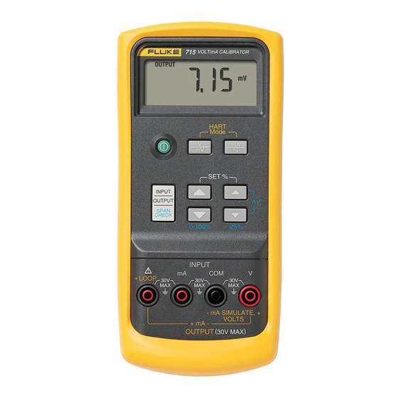
The Fluke 715 Volt/mA Calibrator is a source and measurement
tool for 0 to 24 mA current loop testing and dc voltage from 0 to
20/25 V. The calibrator does not source and measure
simultaneously.
Your calibrator is supplied with a holster, a set of test leads, an
installed 9 V alkaline battery, and this instruction sheet.
Function
dc mV input
dc mV output
dc V input
dc V output
dc mA input
dc mA output
Loop power
output
PN 650314 July 1997 Rev. 3, 8/05
1997-2005 Fluke Corporation. All rights reserved. Printed in U.S.A.
All product names are trademarks of their respective companies.
Volt/mA Calibrator
Summary of Calibrator Capabilities
0 to 200 mV
0 to 25 V
0 to 20 V
0 to 24 mA
24 V dc output
Instruction Sheet
Range
715
Resolution
0.01 mV
0.001 V
0.001 mA
N/A
®
Advertisement
Table of Contents

Subscribe to Our Youtube Channel
Related Manuals for Fluke 715


Summary of Contents for Fluke 715
- Page 1 Volt/mA Calibrator Instruction Sheet Introduction The Fluke 715 Volt/mA Calibrator is a source and measurement tool for 0 to 24 mA current loop testing and dc voltage from 0 to 20/25 V. The calibrator does not source and measure simultaneously.
- Page 2 Contact your Fluke distributor for information about accessories. To order replacement parts or spares, see “Replacement Parts.” To contact Fluke, call one of the following telephone numbers: USA and Canada: 1-888-99-FLUKE (1-888-993-5853) Europe: +31 402-675-200 Japan: +81-3-3434-0181...
-
Page 3: Safety Information
Safety Information Use the calibrator only as specified in this sheet, otherwise the protection provided by the calibrator may be impaired. A Warning identifies conditions and actions that pose hazard(s) to the user; a Caution identifies conditions and actions that may damage the calibrator or the equipment under test. - Page 4 With the Calibrator OFF, press the key. P.S.xx is displayed, where xx is the turn-off time in minutes. OFF means the power saver is disabled. Press and/or to increase or decrease the turn- off time in minutes. To disable, press until the display shows OFF.
-
Page 5: Measuring Dc Volts
Measuring dc Volts INPUT mV or V depending on range Press to toggle Press so that mV and INPUT is on V ranges the display it01i.eps Sourcing dc Volts OUTPUT mV or V depending on range Press to toggle mV and V ranges Press so that OUTPUT is on the display... - Page 6 Measuring dc mA INPUT Press to toggle mA and % of 4-20 mA scale Press so that INPUT is on the display it03i.eps...
-
Page 7: Measuring Dc Ma With Loop Power
Measuring dc mA with Loop Power INPUT Press to toggle mA and % of 4-20 mA scale Press so that INPUT is on the display +24V output Two-wire transmitter HART Communicator it06i.eps... -
Page 8: Using The Current Output Modes
Using the Current Output Modes The calibrator provides current output in mA or percent display. Percent is -25.00 to 125.00%, where 0% is 4 mA, and 100% is 20 In source mode, the calibrator supplies the current. In simulate mode, the calibrator simulates a two-wire transmitter in an externally-powered current loop. -
Page 9: Simulating A Transmitter
Simulating a Transmitter Use simulate mode when an external 24 to 30 V loop power supply is available. Insert the test leads into the mA SIMULATE jacks as shown below. OUTPUT Press to toggle mA and % of 4-20 mA scale Press to step up/down 4 mA (25%) Press to scroll... -
Page 10: Maintenance
Review this sheet to make sure you are using the correct jacks and pushbuttons. If the calibrator needs repair, contact a Fluke Service Center. If the calibrator is under warranty, see the warranty statement below for terms. If the warranty has lapsed, the calibrator will be repaired and returned for a fixed fee. -
Page 11: Replacing The Battery
Calibrate your calibrator once a year to ensure that it performs according to its specifications. A calibration manual is available (PN 686540). Call 1-800-526-4731 from the USA and Canada. In other countries, contact a Fluke Service Center. Replacing the Battery Warning... -
Page 12: Replacement Parts And Accessories
Replacement Parts and Accessories Replacement Parts PN or Item Description Model Qty. 9V battery, ANSI/NEDA 1604A or 614487 IEC 6LR61 H80M Holster, Yellow, hanging H80M MP85 Case top 620200 MP86 Case bottom 2397526 H2, 3, 4 Case screw 832246 MP89, 90 Non-skid foot 824466 O-ring for input/output receptacle... - Page 13 MP85 MP86 H2, 3, 4 MP89, 90 H5, 6 MP92 Instruction AC72 Sheet Alligator Clips TL75 Test Lead Set Holster it10c.eps...
-
Page 14: Specifications
Specifications Specifications are based on a one year calibration cycle and apply from +18 C to +28 C unless stated otherwise. “Counts” means number of increments or decrements of the least significant digit. DC V Input and Output Range Resolution Accuracy, (% of Reading + Counts) 200 mV... -
Page 15: General Specifications
General Specifications Maximum voltage applied between any jack and earth ground or between any two jacks: 30 V Storage temperature: -40 C to 60 C Operating temperature: -10 C to 55 C Operating altitude: 3000 meters maximum Temperature coefficient: 0.005% of range per C for the temperature ranges -10 to 18 C and 28 to 55 C Relative humidity: 95% up to 30 C, 75% up to 40 C, 45% up to 50 C, and 35% up to 55 C... - Page 16 LIMITED WARRANTY & LIMITATION OF LIABILITY This Fluke product will be free from defects in material and workmanship for three years from the date of purchase. This warranty does not cover fuses, disposable batteries or damage from accident, neglect, misuse or abnormal conditions of operation or handling.
Need help?
Do you have a question about the 715 and is the answer not in the manual?
Questions and answers