
Related Manuals for Fluke 718-100G


Summary of Contents for Fluke 718-100G
- Page 1 ® 718 Series Pressure Calibrator Users Manual July 1998 Rev. 4, 3/06 © 1998-2006 Fluke Corporation. All rights reserved. Printed in U.S.A. All product names are trademarks of their respective companies.
-
Page 3: Table Of Contents
Calibrating a P/I Transmitter................... 10 Using the Internal Pump .................... 10 Pump Valve Assembly Cleaning Instructions ..............15 Using an External Pump....................16 External Fluke Pressure Module Compatibility ............... 18 Sourcing Loop Voltage ....................19 Percent Error Setup......................19 Maintenance........................20 In Case of Difficulty.................... - Page 4 Replacing the Batteries ..................... 21 Parts and Accessories ....................22 Specifications......................... 25 Pressure Sensor Input ....................25 Pressure Module Input ....................25 DC mA Input ......................25 Loop Supply ......................25 General Specifications ....................26 How to Contact Fluke..................... 27...
- Page 5 List of Tables Table Title Page Input Units ..........................2 Safety Information ......................... 3 International Electrical Symbols..................... 5 Pushbutton Functions......................7 Pump Features ........................10 Recommended Pressure Modules ..................14 Fluke Pressure Module Compatibility ..................18 Replacement Parts ........................ 22...
- Page 6 718 Series Users Manual...
-
Page 7: List Of Figures
List of Figures Figure Title Page Connection Technique......................5 Front Panel Features......................6 Pump Features ........................9 Internal Pressure Sensor with Internal Pump ................ 12 Pressure Module with Internal Pump..................13 Pressure Module with External Pump..................17 Sourcing Loop Voltage ......................19 Battery Replacement ...................... - Page 8 718 Series Users Manual...
-
Page 9: Introduction
Pressure sensor specifications are as listed under Measure pressure via a 1/8-inch NPT pressure fitting “Pressure Sensor Input”. and an internal pressure sensor or via a Fluke 700 Series Pressure Module The Calibrator measures pressure sensor inputs in the Source pressure units shown in Table 1. -
Page 10: Safety Information
718 Series Users Manual “How to Contact Fluke.” To order replacement parts or Safety Information spares, see “Parts and Accessories.” Use the Calibrator only as specified in this Users Manual, otherwise the protection provided by the Calibrator may be Table 1. Input Units impaired. -
Page 11: Safety Information
Pressure Calibrator Safety Information Table 2. Safety Information XW Warning To avoid possible electric shock or personal injury: Never apply more than 30 V between the mA terminals, or between either of the mA terminals and earth ground. Do not use the Calibrator to make measurements in a CAT II, CAT III, or a CAT IV environment. CAT I equipment is designed to protect against transient from high-voltage, low-energy sources, such as electronic circuits or a copy machine Remove the test leads from the Calibrator before you open the battery door. - Page 12 718 Series Users Manual Table 2. Safety Information (cont.) XW Warning To avoid false readings, which could lead to possible electric shock or personal injury, replace the battery as soon as the battery indicator appears. To avoid a violent release of pressure in a pressurized system, shut off the valve and slowly bleed off the pressure before you attach or detach the internal pressure sensor or pressure module fitting to the pressure line.
-
Page 13: International Electrical Symbols
Pressure Calibrator Safety Information Table 3. International Electrical Symbols Symbol Meaning Earth ground Fuse Battery Refer to this instruction sheet for information about this feature. Hazardous voltage. Risk of electric Hold in shock. fixed Double insulated position Conforms to relevant Canadian Standards Association directives. -
Page 14: Getting Acquainted With The Calibrator
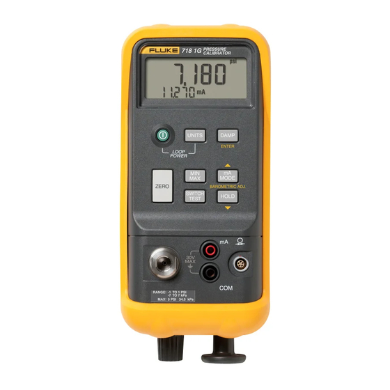
718 Series Users Manual Getting Acquainted with the Calibrator Press to turn the Calibrator on and off. The Calibrator Pressure measurement displays pressure and current measurements simultaneously. See Figure 2. The upper part of the display shows the applied pressure or vacuum. -
Page 15: Pushbutton Functions
Pressure Calibrator Getting Acquainted with the Calibrator Table 4. Pushbutton Functions Pushbutton Description Press to select a different pressure unit. All units are available when the pressure sensor input is used. For higher pressure module inputs, inappropriate (out-of-range) units are not available. Press on while pressing to source loop voltage. -
Page 16: Switch Test
718 Series Users Manual Switch Test Press to enter pressure switch test mode. The Calibrator will display CLOSE instead of a mA To perform a switch test, do the following: measurement. Note Apply pressure with the pump slowly until the switch opens. -
Page 17: Zeroing With Absolute Pressure Modules
Pressure Calibrator Zeroing with Absolute Pressure Modules Zeroing with Absolute Pressure Modules For zeroing, adjust the Calibrator to read a known pressure. This can be barometric pressure, if it is accurately known, for all but the 700PA3 module. An accurate pressure standard can also apply a pressure within range for any Absolute Pressure Module. -
Page 18: Calibrating A P/I Transmitter
Increase pressure on the inward stroke. Pump In vacuum mode, decrease pressure on The internal pump can also be used with certain Fluke 700 the outward stroke. Series Pressure Modules. In this case, pressure measured by the Pressure Module is displayed by the Calibrator. - Page 19 Pressure Calibrator Calibrating a P/I Transmitter XW Warning Turn the fine adjustment knob to mid-range. If both a pressure module and the internal Turn the pressure/vacuum release control forward sensor are connected, the Calibrator displays (clockwise) to close the release valve. ONLY the pressure module measurement.
- Page 20 718 Series Users Manual Black S I G N A L – T E S T wh002f.eps Figure 4. Internal Pressure Sensor with Internal Pump...
- Page 21 Pressure Calibrator Calibrating a P/I Transmitter S I G N A L – Pressure Module T E S T Black wh010f.eps Figure 5. Pressure Module with Internal Pump...
-
Page 22: Recommended Pressure Modules
718 Series Users Manual Table 6. Recommended Pressure Modules External External Internal Internal Pump Pressure Pressure pump Pump Pump Module Module All 718 models 100G 300G all models 100G 300G 700 PA3 700 P00 700 PA4 700 P01 700 PA5 700 P02 700 PA6 700 P22... -
Page 23: Pump Valve Assembly Cleaning Instructions
Pressure Calibrator Pump Valve Assembly Cleaning Instructions Once all parts have been cleaned and inspected, Pump Valve Assembly Cleaning reinstall the o-ring and spring assemblies into the Instructions valve body. Using a small screwdriver, remove the two valve Reinstall the retention caps and gently tighten the retention caps located in the oval shaped opening on cap. -
Page 24: Using An External Pump
To develop higher pressure or vacuum, use an external pump (such as the Fluke Model 700PTP). Use a Fluke Pressure Module connected to the pressure module input on the Calibrator. Pressure modules are listed in Table . - Page 25 Pressure Calibrator Using an External Pump S I G N A L Pressure Module – T E S T Black wh006f.eps Figure 6. Pressure Module with External Pump...
-
Page 26: External Fluke Pressure Module Compatibility
Users Manual External Fluke Pressure Module Compatibility If inappropriate units are selected, the output of Fluke 700P Pressure Modules can cause the Calibrator display to overflow (OL), or displays values that are too low to be read. Refer to Table 7 for appropriate unit and range compatibility. -
Page 27: Sourcing Loop Voltage
Pressure Calibrator Sourcing Loop Voltage Sourcing Loop Voltage Percent Error Setup The Calibrator can supply loop power at 24 V dc to a Press and hold . After 3 seconds the set icon and 0% current transmitter that is disconnected from the system. appears on the lower display. -
Page 28: Maintenance
Calibration injury, or sudden release of pressure, review “Safety Information” earlier in this manual Fluke recommends that you calibrate your Calibrator once before proceeding. a year to ensure that it performs according to its specifications. A calibration manual is available (PN Remove test leads before opening. -
Page 29: Replacing The Batteries
Pressure Calibrator Maintenance Replacing the Batteries When the symbol appears on the display, replace the two 9 V alkaline batteries. Refer to Figure 8. XW Warning To avoid false readings, which could lead to possible electric shock or personal injury, replace the batteries as soon as the battery indicator appears. -
Page 30: Parts And Accessories
718 Series Users Manual Parts and Accessories Refer to Table 8 and Figure 9. Table 8. Replacement Parts Item Description Part/ Mod. No. Alligator clip red 1670641 AC72 Alligator clip black 1670652 BT1, BT2 9 V battery, ANSI/NEDA 1604A or IEC 6LR61 614487 Holster Holster, Yellow... - Page 31 Pressure Calibrator Parts and Accessories Table 8. Replacement Parts (cont.) Item Description Part/ Mod. No. MP10 Pump handle knob 664185 MP11, 12, 13 O-ring 146688 MP14 Spacer 687449 MP85 Case top/connector, 718 1G, 30G, 100G, 300G 2546299 MP86 Case bottom 664174 MP89, 90 Non-skid foot...
- Page 32 718 Series Users Manual MP85 Holster MP14 MP11,12,13 AC72 H7,8 Alligator Clips MP3,4 TL75 Test Lead Set MP86 MP92 H5,6 MP10 H2,3,4 MP89,90 wh004f.eps Figure 9. Replacement Parts...
-
Page 33: Specifications
Pressure Calibrator Specifications Pressure Module Input Specifications Specifications are based on a one year calibration cycle Range Resolution Accuracy and apply for ambient temperature from +18 C to +28 C unless stated otherwise. “Counts” are the number of (determined by Pressure Module) increments or decrements of the least significant digit. -
Page 34: General Specifications
718 Series Users Manual General Specifications Shock: 1 meter drop test, per IEC 61010-1 Safety: Certified as compliant to ISA-82.02.01 (IEC Maximum voltage applied between either mA terminal 61010-1 Mod) CSA C22.2 No. 1010.1 and earth ground or between the mA terminals: 30 V Protection Class: Class 2, Double insulated Storage temperature: -40 C to 60 C Power requirements: Two 9 V batteries (ANSI/NEDA... -
Page 35: How To Contact Fluke
LIMITED WARRANTY & LIMITATION OF LIABILITY To order accessories, receive operating assistance, or get This Fluke product will be free from defects in material and workmanship for three years (one year for pump assembly) from the date of purchase. the location of the nearest Fluke distributor or Service... - Page 36 718 Series Users Manual...
Need help?
Do you have a question about the 718-100G and is the answer not in the manual?
Questions and answers