Table of Contents
Advertisement
Quick Links
Operatore elettromeccanico per cancelli ad anta battente
Istruzioni d'uso ed avvertenze
Electro-mechanical operator for swing gates
Operating instructions and warnings
Opérateur électromécanique pour portails battants
Notice d'emploi et avertissements
Operador electromecánico para puertas con hoja batiente
Instrucciones de uso y advertencias
Operador electromecânico para portões de folha batente
Instruções para utilização e advertências
Siłownik elektromechaniczny do bram skrzydłowych
Instrukcja montażu i użytkowania
SWINGER
Advertisement
Table of Contents

Subscribe to Our Youtube Channel
Related Manuals for Dea SWINGER


Summary of Contents for Dea SWINGER
- Page 1 Opérateur électromécanique pour portails battants Notice d’emploi et avertissements Operador electromecánico para puertas con hoja batiente Instrucciones de uso y advertencias Operador electromecânico para portões de folha batente Instruções para utilização e advertências Siłownik elektromechaniczny do bram skrzydłowych Instrukcja montażu i użytkowania SWINGER...
- Page 2 The D ec l a r a t ion of I n c orpor at io n may be c o n sul ted by en ter in g h t t p: //w w w. deas ys tem. c om DEA SYSTEM S.p.A. Via Della Tecnica, 6...
-
Page 3: Product Conformity
A P P R O P R I A T E O C A M U N I C I P A R E C Y C I N G Note: Geko is the manufacturer’s name for the Swinger, and may be referenced in this manual. -
Page 4: Product Description
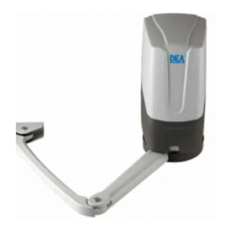
2 PRODUCT DESCRIPTION Models and contents of the package GEKO is an operator for the automation of swing gates and doors with door medium and small size. It is essentially made up of: - an operator; - a programmable control panel (adjustable strength, speed, operators stroke, etc..) with built-in 433.92 MHz radio receiver; Inspect the “Contents of the package”... -
Page 5: Electrical Connections
4.4 How to fix and adjust the mechanical limit switches • Unlock the operator; • Rotate the wing to the position of complete opening, position the mechanical limit switch on the stop with the straight arm and fasten it with the provided screws (Pic. 10). If necessary, you can mount a second mechanical limit switch for the closing stop. In this case follow the above directions by moving the door in the desired closed position and fix it with the screws provided in detention;... - Page 6 OPEN GATE WARNING LIGHT 24V 15w ELECTRIC LOCK art.110 N.O. N.C. N.O. N.C. CON3 BLUE BROWN GREEN WHITE CON2...
-
Page 7: Standard Programming
6 STANDARD PROGRAMMING 1 Power Supply Give power supply, the display shows the following symbols “ ”, “ ”, “ ” and then “- - - -”. If the control panel has already been programmed and the power fails or is switched off - once power is returned and a START command is given, the position reset procedure is performed (see “rESP”... - Page 8 5 Selection 1 or 2 operators functioning 1. Scroll down the parameters with keys until you visua- lise P030; 2. Access the parameter by pressing the key; 3. Acting on keys, set: - d001=for a single motor operating; - d002=for 2 motors operating; 4.
-
Page 9: Adjustment Of Operating Parameters
7.2 Learning 1. Scroll down the parameters with keys until you visualise P005; 2. Confirm by pressing on the key; 3. When the symbol “ ” appears, press on any key of the transmitter you want to memo- rize; 4. The display visualizes the number of the trans- mitter just memorized and then “... -
Page 10: Advanced Programming
7 ADVANCED PROGRAMMING Here are some added programming procedures relating to remotes memory management and advanced configuration of the control inputs. 1 Deletion of memorized transmitters 1.1 Deletion of all transmitters 1. Scroll down the parameters until you visualize P004; 2. -
Page 11: Inputs Configuration
3.2 Unlocking access to programming 1. Scroll through the parameters with the buttons until the display shows P008; 2. Access the parameter by pressing the button 3. The display shows alternately the writing to indicate that the control board is waiting for the transmission of the unlocking code;... -
Page 12: Messages Shown On The Display
9.1 Installation test The testing operation is essential in order to verify the correct installation of the system. DEA System wants to summarize the proper testing of all the automation in 4 easy steps: •... -
Page 13: Maintenance
6 months observed in order to find the solution to the problem and contact greasing of articulated joint 1 year DEA System directly whenever the solution required is not provided. TROUBLE-SHOOTING Description Possible solutions The operator is not receiving correct power supply. Check all connections, fuses, and the When the opening command is given, the gate wing fails to power supply cable conditions and replace or repair it if necessary. - Page 14 PROGRAMMING PROCEDURES INPUTS CONFIGURATION PARAMETERS...
- Page 15 INPUTS CONFIGURATION OPERATORS OPERATING PARAMETERS PARAMETERS CONFIGURATION PARAMETERS...
- Page 16 OPERATING PARAMETERS...
- Page 17 OPERATING PARAMETERS...
- Page 19 Exclusive Australian Distributor Customer Service (03) 9364 8288 See downee.com.au for your state office Tech Support 1800 241 733 techsupport@downee.com.au downee.com.au deasystem.com...
Need help?
Do you have a question about the SWINGER and is the answer not in the manual?
Questions and answers