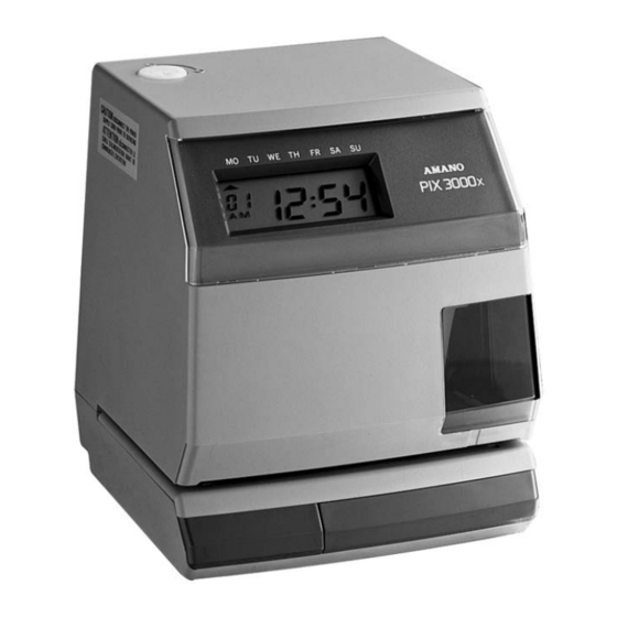
Amano PIX-3000x Manual
Electronic time recorder
Hide thumbs
Also See for PIX-3000x:
- Service parts (18 pages) ,
- Operation manual (40 pages) ,
- Operation manual (36 pages)
Table of Contents
Advertisement
Quick Links
Advertisement
Table of Contents

Related Manuals for Amano PIX-3000x


Summary of Contents for Amano PIX-3000x
- Page 1 Electronic Time Recorder PIX-3000x Options Manual...
-
Page 2: Proprietary Notice
This document contains proprietary information and such information may not be reproduced in whole or part without the written permission from Amano Cincinnati, Inc. 140 Harrison Ave., Roseland, New Jersey 07068. Amano Cincinnati, Inc. reserves the right to make equipment changes and improvements that may not be reflected in this document. -
Page 3: Table Of Contents
Chapter 5: PIXCOMW............13 Introduction ................13 Network Topology ..............13 PIX Operation................14 PIX RS485 Hardware Specifications........14 PIXCOMW Communication Specifications....... 15 Data Format ................16 Checksum (BCC) ..............17 Error Detection ................. 17 Software Operation ..............17 PIX-3000x Options Manual... - Page 4 PIX-3000x Options Manual...
-
Page 5: Chapter 1: Introduction
Small flat screwdriver for inserting wires into the options terminal block • Philips #2 screwdriver for the installation of options PCB • This Options Manual • The PIX-3000x Operations Manual • PIXCOMW Software and Installation and Configuration Guide (If applicable) PIX-3000x Options Manual... - Page 6 PIX-3000x Options Manual...
-
Page 7: Chapter 2: Signal Output
(example: ESA-100010, S-1205) with a load as shown above. It is recommended that you use a 12, 18, 24 or 30- volt signal device. If this is not available, an external relay should be used for 110V signals. PIX-3000x Options Manual... - Page 8 PIX-3000x Options Manual...
-
Page 9: Chapter 3: Master And Slave Function
The Master and Slave function of the PIX-3000x synchronizes the PIX's connected to each other (up to 6). The Master & Slave functions of the PIX-3000x consists of one (1) Master clock and a maximum of five (5) Slave units. The PIX does not have an hourly correction of minutes. -
Page 10: Jumpers And Connections
Jumpers and Connections • Disconnect AC power before connection. • Maximum wire distance in one direction is 2000ft. at 22 AWG. PIX-3000x Options Manual... -
Page 11: Terminal Block Wiring
Terminal Block Wiring 1. Remove the cover case. 2. Remove wall mount plate. Refer to the Wall Mounting and Cover Removal sections of the PIX-3000x Operations manual. 3. Use flat screwdriver to open TB1 as indicated. 4. Insert option wires into TB1. -
Page 12: Master/Slave And Signal Output Pcb Installation
12. Plug in the 6-pin connector on the options board to the 6-pin connector on the power board. 13. Reinstall the inside cover, taking care not to damage the programming buttons. PIX-3000x Options Manual... -
Page 13: Chapter 4: Programming
6. Final confirmation. All digits will blink. Press the CHANGE button if you do not want to save the signal program data and reprogram the signals you do want. 7. Press ENTER to save and move to next signal program number. PIX-3000x Options Manual... -
Page 14: Signaling Time Duration
1. To receive symbol program data select the indicated screen. 2. Press the ENTER button to wait for the reception of data from the Master PIX. 3. When the data has been successfully received, the PIX will display "End". PIX-3000x Options Manual... -
Page 15: Error Codes
2. Press ENTER to send data to Slave Clock. 3. After all data is sent, the PIX will display "End". Error Codes Error Code Display Parity Error Check Sum Error 2-Minute Time Out PIX-3000x Options Manual... - Page 16 PIX-3000x Options Manual...
-
Page 17: Chapter 5: Pixcomw
PIX-3000x's (Recommended: LD485A-MP). PIXCOMW allows time/date information obtained from either the user or ACTS* to be sent out from up to 4 serial ports. When communicating to the PIX-3000x's, each unit will be disabled from performing other functions for a period ranging from one to three seconds. -
Page 18: Pix Operation
PC are complete. If an error occurs during transmission, the top row of day indicators will flash. During this error condition, all functions of the PIX-3000x will continue to operate normally. If an error occurs during communications, two actions can be taken to reset the display: Pressing the reset button or using the PC to resend the time and date to the PIX machines. -
Page 19: Pixcomw Communication Specifications
Data Bits Stop Bits Time Offset When transmitting the time to the PIX-3000x, the application will add two seconds to compensate for transmission time. The time offset occurs immediately before the time is sent out. The offset is determined by... -
Page 20: Data Format
Data Format When the data is sent to the PIX-3000x, all the data is represented by the hex equivalent of the ASCII values. The transmission string contains 200 characters, 165 leading 0's, data type [DF], terminal number [00], (4) Date/Time blocks and an overall checksum. -
Page 21: Checksum (Bcc)
One of these blocks is chosen as the Date/Time information. If the PIX-3000x is unable to set the Date/Time, an error message will be displayed on the PIX. The only way to remove this message is to reset the PIX or to retransmit the Date/Time correctly. - Page 22 PIX-3000x Options Manual...
- Page 24 AJR-189300 Copyright © 2005 Amano Cincinnati, Inc. Printed in USA 4/05/0...
Need help?
Do you have a question about the PIX-3000x and is the answer not in the manual?
Questions and answers