
Related Manuals for AUVIO 40-268


Summary of Contents for AUVIO 40-268
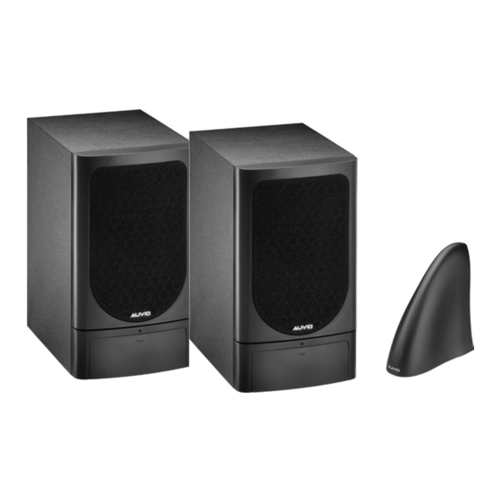
- Page 1 THE PERFORMANCE YO U NEED Wireless Amplified Stereo Speakers Please read this user’s guide before using your new speakers Please read XX-XXX this User’s User’s Guide User’s Guide 40-268...
-
Page 2: Table Of Contents
Contents Package Contents ....................4 Features ......................... 5 Setup ........................5 1. Select a location ................... 5 2. Attach rubber feet to speakers ..............6 3. Power the system ..................6 4. Connect to an audio source ................ 8 5. Stereo/Mono Setup ................... 10 6. - Page 3 ..4 Care ......................... 14 Troubleshooting ..................... 15 ..5 Specifications ....................16 ..5 FCC Information ..................... 17 ..5 Limited Warranty.................... 18 ..6 ..6 ..8 ..10 ..11 ..12 ..13 ..13 ..14 ..
-
Page 4: Package Contents
Package contents Feat RCA jack to 3.5mm Plug Speaker Transmitter (Y-Adapter) In orde AC Adapter for Speakers (2) AC Adapter for Transmitter 3.5mm to 6.3mm adapter Quick Start Stereo audio cable Rubber feet (8) -
Page 5: Features
Features Ideal for use as rear-channel speakers in your surround-sound home theater. Enables you to listen to your stereo in any room of your home. True stereo sound, with individual bass and treble controls. Plug Setup Select a location In order to achieve the best performance: Position the transmitter as far as possible from other electronic devices such ... -
Page 6: Attach Rubber Feet To Speakers
Attach rubber feet to speakers You als batteri Remove the backing on the bottom of the rubber feet and attach them to the four corners on the bottom of each speaker. To ins Po�er the s�ste� Po�er the s�ste� Connect the supplied AC power adapters into the DC 12V jacks on the transmitter and speakers, then plug the adapters into standard AC outlets. - Page 7 You also can use 16 (8 for each speaker) D size batteries (not supplied) to power the speakers. To install the batteries: Remove the battery cover. Insert 8 batteries for each speaker with mitter correct polarities. Replace the cover when finished. Caution: You must use a Class 2 power source that supplies 12 volts DC and delivers at least 250mA or 1250mA.
-
Page 8: Connect To An Audio Source
Battery Notes Using the AC adapter overrides any installed batteries. When the speakers POWER LED blinks, replace the batteries. Do not burn or bury batteries. Do not puncture or crush. Do not disassemble. Use only fresh batteries of the required size and recommended type. ... - Page 9 Connect one end of the supplied audio cable to the transmitter’s audio jacks (white plug to L AUDIO IN and red plug to R AUDIO IN). Connect to your audio source’s output jacks: Connect the white and red plugs at the other end of the cable into the mble.
-
Page 10: Stereo/Mono Setup
Caution: Do not connect the transmitter to your audio source’s speaker output. It could damage the transmitter and the audio source. If you connected the transmitter to an audio source’s headphone jack, set the audio source’s volume control to its middle position. Stereo/�ono setup transm For normal stereo use, set STEREO/... -
Page 11: Select Channel
Select channel could Set the transmitter to a frequency channel (CHANNEL 1, 2, or 3) that has no interference. t the Set the speaker to the same channels as the transmitter. Note: If you receive interference, try changing the channel number on the transmitter and the speakers. -
Page 12: Mount The Speakers
Mount the speakers To mount a speaker on the wall, you need two screws (not supplied) with a head Turn that fits into the keyhole slot on the back of the speaker. Select a location and drill a hole to fit your screws. Thread each screw into the hole until the screw’s head extends about inch (15mm) from the wall. -
Page 13: Basic Operation
Basic Operation Turn on Turn on your audio source. The transmitter has a built-in automatic ON/OFF controller. When the AC inch adapter is plugged in and the transmitter receives audio signals from the audio source, the transmitter’s power LED lights blue. The transmission stops if the transmitter does not receive audio signals from the audio source for about one minute. -
Page 14: Additional Information
Additional Information Listening Safet� with a To protect your hearing, follow these guidelines when you use the speaker system. Trou Set the volume to the lowest setting before you begin listening. After you begin listening, adjust the volume to a comfortable level. We do Do not listen at extremely high volume levels. -
Page 15: Troubleshooting
Keep the system away from dust and dirt, and wipe it with a damp cloth occasionally to keep it looking new. Caution: You might permanently damage your speakers by cleaning them with a vacuum cleaner. Use a feather duster or a soft cloth instead. ystem. -
Page 16: Specifications
Speake Audio is Be sure the speakers and transmitter are set to the same channel. Sensitiv distorted If the transmitter is connected to an audio source’s headphone S/N Rad jack, reduce the audio source’s volume. Audio D Change the position of the transmitter. ... -
Page 17: Fcc Information
Speaker nnel. Sensitivity ......................<2µV (with 20 dB S/N) S/N Radio (@-50 dBm) ..................>=70 dB (A weight) Audio Distortion ........................... <2% Max. Audio output ........................>=10W Approximate Measurement (HWD) ................11 × 6 × 7½ in ........................... (280 × 150 × 195 mm) Power Source ..........2 regulated AC adapters (AC 120/60Hz;... - Page 18 Connect the equipment into an outlet on a circuit different from that to which the receiver is connected. are warr Consult the dealer or an experienced radio/TV technician for help. ment of Changes or modifications not expressly approved by Ignition L.P . may cause interference and void the IGNITIO user’s authority to operate the equipment.
-
Page 19: Limited Warranty
nected. are warranted for the remainder of the original warranty period. You will be charged for repair or replace- ment of the product made after the expiration of the warranty period. IGNITION L.P . EXPRESSLY DISCLAIMS ALL WARRANTIES AND CONDITIONS NOT STATED IN THIS LIMITED WARRANTY. - Page 20 Printed Inc. All rights in China 06A09 40-268 © 2009. Ignition L.P . All rights reserved. Auvio is a trademark used by Ignition L.P . AO0367AAA1 Package and user’s guide are recyclable. User’s guide contains recycled material. User’s Guide 40-268...
Need help?
Do you have a question about the 40-268 and is the answer not in the manual?
Questions and answers