Table of Contents
Advertisement
Quick Links
Advertisement
Table of Contents

Related Manuals for Tektronix PA1000


Summary of Contents for Tektronix PA1000
- Page 1 PA1000 Power Analyzer User Manual *P077091201* 077-0912-01...
- Page 3 PA1000 Power Analyzer User Manual Firmware Version 1.003.012 and above www.tektronix.com 077-0912-01...
- Page 4 Copyright © Tektronix. All rights reserved. Licensed software products are owned by Tektronix or its subsidiaries or suppliers, and are protected by national copyright laws and international treaty provisions. Tektronix products are covered by U.S. and foreign patents, issued and pending. Information in this publication supersedes that in all previously published material.
- Page 5 Tektronix, with shipping charges prepaid. Tektronix shall pay for the return of the product to Customer if the shipment is to a location within the country in which the Tektronix service center is located. Customer shall be responsible for paying all shipping charges, duties, taxes, and any other charges for products returned to any other locations.
-
Page 7: Table Of Contents
View ......................Connecting signals ....................Input overview ....................To connect a simple current transformer ..............To connect an external resistive shunt ..............To connect a transducer with a voltage output............. To connect a voltage transformer / transducer ............. PA1000 Power Analyzer... - Page 8 Sending and receiving commands ................Communications examples .................. Software ......................PWRVIEW PC software ..................PA1000 firmware update utility ................Applications examples .................... IEC 62301 compliance testing and low-power standby measurements ........ IEC 61000-3-2 pre-compliance current harmonics testing ..........Specifications ......................
- Page 9 Figure 17: PWRVIEW application ................Figure 18: Laptop charger full-compliance standby power test with PWRVIEW software....Figure 19: PA1000 measuring 5 mW in front-panel standby mode.......... Figure 20: Standby power measurement connections ............Figure 21: IEC 61000-3-2 pre-compliance test running on PWRVIEW software ......
- Page 10 Table of Contents List of Tables Table 1: Standard accessories ..................Table 2: Optional accessories ..................Table 3: Service options ................... Table 4: Available measurements per mode ..............Table 5: Phase measurements ..................Table 6: Power polarity ................... PA1000 Power Analyzer...
-
Page 11: Important Safety Information
To avoid electric shock, the grounding conductor must be connected to earth ground. Before making connections to the input or output terminals of the product, make sure that the product is properly grounded. PA1000 Power Analyzer... - Page 12 Use only insulated voltage probes, test leads, and adapters supplied with the product, or indicated by Tektronix to be suitable for the product. Observe all terminal ratings. To avoid fire or shock hazard, observe all ratings and markings on the product.
-
Page 13: Service Safety Summary
Only qualified personnel should perform service procedures. Read this Service safety summary and the General safety summary before performing any service procedures. To avoid electric shock. Do not touch exposed connections. PA1000 Power Analyzer... -
Page 14: Terms In This Manual
When this symbol is marked on the product, be sure to consult the manual to find out the nature of the potential hazards and any actions which have to be taken to avoid them. (This symbol may also be used to refer the user to ratings in the manual.) viii PA1000 Power Analyzer... - Page 15 Important safety information The following symbol(s) may appear on the product: PA1000 Power Analyzer...
-
Page 16: Compliance Information
IEC 61000-4-6:2003. Conducted RF immunity IEC 61000-4-11:2004. Voltage dips and interruptions immunity EN 61000-3-2:2006. AC power line harmonic emissions EN 61000-3-3:1995. Voltage changes, fluctuations, and flicker European contact. Tektronix UK, Ltd. One Thames Valley Wokingham Road Bracknell, RG42 1NG United Kingdom PA1000 Power Analyzer... -
Page 17: Safety Compliance
EN 61010-1. Safety Requirements for Electrical Equipment for Measurement, Control, and Laboratory Use – Part 1: General Requirements. EN 61010-2-030. Safety Requirements for Electrical Equipment for Measurement, Control, and Laboratory Use – Part 2-030: Particular requirements for testing and measuring circuits. PA1000 Power Analyzer... - Page 18 These are sheltered locations where neither temperature nor humidity is controlled. The area is protected from direct sunshine, rain, or direct wind. Pollution degree 4. Pollution that generates persistent conductivity through conductive dust, rain, or snow. Typical outdoor locations. PA1000 Power Analyzer...
- Page 19 Only mains power supply circuits have an overvoltage category rating. Only measurement circuits have a measurement category rating. Other circuits within the product do not have either rating. Mains overvoltage Overvoltage category II (as defined in IEC 61010-1). category rating PA1000 Power Analyzer xiii...
-
Page 20: Environmental Considerations
Union requirements according to Directives 2002/96/EC and 2006/66/EC on waste electrical and electronic equipment (WEEE) and batteries. For information about recycling options, check the Support/Service section of the Tektronix Web site (www.tektronix.com). Restriction of hazardous This product is classified as an industrial monitoring and control instrument,... -
Page 21: Preface
Preface Preface This manual covers the setup and use of the PA1000 Power Analyzer. Specifications and remote operation, including programming commands, are included in later chapters. PA1000 Power Analyzer... - Page 22 Preface PA1000 Power Analyzer...
-
Page 23: Introduction
Introduction The Tektronix PA1000 is a powerful and versatile precision power analyzer. Designed to provide clear and accurate measurements of electrical power and energy on all single-phase electrical products, the PA1000 is an easy-to-use bench instrument with capability for remote control, data transfer and regulatory compliance testing. -
Page 24: Standard Accessories
Breakout box (United Kingdom plug configuration) BB1000-UK Specialty current transducer for lamp ballast testing BALLAST-CT Current clamp, 1 A - 200 A, for Tektronix Power Analyzers CL200 Current clamp, 0.1 A - 1200 A, for Tektronix Power Analyzers CL1200 Replacement lead set for Tektronix Power Analyzers (one... -
Page 25: Service Options
Opt. C3 Calibration Service 3 Years Opt. C5 Calibration Service 5 Years Opt. D1 Calibration Data Report Opt. D3 Calibration Data Report 3 Years (with Option C3) Opt. D5 Calibration Data Report 5 Years (with Option C5) PA1000 Power Analyzer... -
Page 26: Getting Started
The device may only be used under certain ambient conditions. Ensure that the actual ambient conditions conform to the admissible conditions specified in this manual. Ensure this product is installed in such a way that its power cable is accessible at all times and can easily be disconnected. PA1000 Power Analyzer... - Page 27 If you are in doubt as regards the safe operation of the device, immediately shut down the unit and the respective accessories, secure them against inadvertent switching on, and have them serviced by a qualified service person. PA1000 Power Analyzer...
-
Page 28: Power On
3. After pressing the power switch at the front to on: The PA1000 will start its power-on sequence. This takes approximately 5–10 seconds. During power on, you will see the PA1000 serial number and firmware version. 4. The instrument is now ready for use. -
Page 29: Controls And Connectors
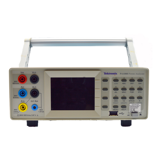
Use this section to help familiarize yourself with the instrument operation. Front panel Figure 3: PA1000 front panel 1. Input banana jacks – For safe operation, use only the test lead set supplied with the instrument. Typical connections for the power analyzer are shown later in this section. -
Page 30: Figure 4: Pa1000 Rear Panel
USB from a PC utility in less than 15 minutes. To locate the latest version of the firmware (and PC software), go to www.tek.com, and browse to the "Power Analyzers" "PA1000" page and then click on the software link or tab. (See page 58, PA1000 firmware update utility.) -
Page 31: Connecting To The Product Under Test
(See page 27, Connecting signals.) To measure power, connect the measuring terminals of the PA1000 in parallel with the supply voltage and in series with the load current as shown below. -
Page 32: Figure 6: Breakout Box
The simplest and safest way to make a connection to the product under test is to use a Tektronix Breakout Box. This provides a line socket for connection of the product and 5 x 4 mm sockets for direct connection to the PA1000 terminals as described above. -
Page 33: Figure 7: Typical Breakout Box Connections
Getting started Connecting the breakout box. 1. Using the test leads provided with the PA1000, make the voltage and current connections between the breakout box and the input jacks on the PA1000. (See Figure 7.) NOTE. The VLO Source jack on the breakout box is designed for taking measurements in low power, standby applications. -
Page 34: Default Measurements
Getting started Default measurements After you switch on the supply to the load, the PA1000 is ready to take measurements. Note that it is not necessary to switch the PA1000 either off or on when the load is being connected. -
Page 35: Navigating The Menu System
Getting started Navigating the menu system The menu system provides complete access to all settings of the PA1000. To access the menu system, press the MENU key. To return to the measurement display at any time, simply press the MENU key again. -
Page 36: Data Logging
The directory structure created will contain the last five digits of the serial number of the PA1000 used and the date at the start of data logging. The file name will reflect the time at the start of data logging in 24 hr format and will have a .CSV extension. -
Page 37: Figure 11: Pa1000 Logged Data
Universal Serial Bus Mass Storage Class – Bulk Only Transport Rev. 1.0, published by the USB Implementers Forum. Most USB memory devices meet the above requirements. Printing Printing directly from the PA1000 is not currently supported, but may be implemented in a future software release. PA1000 Power Analyzer... -
Page 38: Unit Configuration
On the unit configuration screen there are 2 dates related to calibration. They are: (calibration) type Last Verified – This is the date the PA1000 was last checked against specification without any adjustments being made. Last Adjusted – This is the date calibration information was last changed in the PA1000. -
Page 39: The Menu System
See the Quick Start section of this manual for an overview of how to access and use the menu system. (See page 13, Navigating the menu system.) For help at any time while using the PA1000 press the HELP key at any time. Menu items To switch the display of the menu system off or on, press the MENU key at any time. -
Page 40: Modes
The menu system Modes Select mode Choose this option to set the PA1000 into one of its operating modes. Each mode is indicated on the front panel measurement display once set. The modes are: Normal. Ideal for most general measurements. -
Page 41: Table 4: Available Measurements Per Mode
Table 4: Available measurements per mode Mode Measurement Normal Ballast Inrush Standby Power Integrator Watts Freq Vpk+ Vpk– Apk+ Apk– Vthd Athd VAhrs VArhr V-harm A-harm V range A range X = Measurement available X* = Displayed as default PA1000 Power Analyzer... - Page 42 In the Clock Start Method the PA1000 will use its real time clock to start the integrator based on the date and time set up by the user. The user will also configure a duration for the Clock Start Method that will stop the integrator at the...
-
Page 43: Inputs
Inputs Set up the measurement inputs – range, scale and low value blanking. This menu may be used to set up the physical inputs of the PA1000. For normal operation, (20 mA to 20 A and up to 600 V ), it is not necessary to change these settings from default. - Page 44 The frequency filter does not affect the voltage measurement. The filter is for the frequency detection. Shunts The PA1000 is fitted with two internal shunts. The 20 A shunt is suitable for measurements from 20 mA to 20 A . The 1 A shunt is suitable for measurements from 20 μA to 1 A.
-
Page 45: Graphs
The menu system Graphs To set up the graphical displays of the PA1000, select the graph type using the keys and press for options. Hint: Use the YZ key to toggle between graphic and numeric displays. Waveform graph This will display the voltage, current and (optionally) the Watts waveform. The scale of the graph is set automatically according to the selected range and scaling. -
Page 46: Interfaces
When the graph is configured, select Show to view the graph. Note: The PA1000 must be in Integrator mode for the graph to start. Interfaces This menu may be used to set up the interfaces of the PA1000. To select set up an interface, use the keys, and then press for detailed options. - Page 47 For details of the actual equations used, (See page 76, Measured parameters.) Auto and Manual Zero Normally the PA1000 will cancel any small dc offsets in the measurement automatically. This feature is referred to as Auto Zero. Auto Zero. Auto Zero should always be enabled except in certain applications such as Inrush current measurement.
-
Page 48: User Configuration
The menu system Clock setup These options may be used to check or set the PA1000 internal clock. To select a menu item, use the keys and then press for detailed options. Set Time - Enter the time using the format shown and press OK to confirm. -
Page 49: Connecting Signals
Currents of up to 20 A may be connected directly to the blue and black 4 mm AHI and ALO safety sockets at the front of the PA1000 Alternatively, if you are making measurements of less than 1 A , 2 A , connect the current to be measured between the yellow A1A and black ALO connections. -
Page 50: To Connect A Simple Current Transformer
CT output current. For example, the CL200 is a 1000:1 CT. When measuring 100 A, its output is 100 mA. To scale this on the PA1000, a scale factor of 1000 must be entered: Press MENU Select ‘Inputs’... -
Page 51: To Connect An External Resistive Shunt
AHI, A1A, EXT AHI and ALO are connected inside the PA1000 via a low impedance shunt. To avoid errors and a risk of electric shock, remove all connections to AHI and A1A. 3. Set up the PA1000 to measure current from the EXT AHI and ALO terminals. Press MENU Select... -
Page 52: To Connect A Transducer With A Voltage Output
The procedure is similar to that of installing an external shunt as described above. 1. Follow the manufacturer’s instructions for the safe use and installation of the transducer. 2. Connect the voltage output to the EXT-HI and A-LO terminals of the PA1000 as above. 3. Select Inputs – Shunts – External as above. -
Page 53: To Connect A Voltage Transformer / Transducer
The output of the transducer is connected to the normal VHI and VLO terminals. Normally, the positive or HI output of the transducer will be marked with the point of an arrow or a + symbol. Connect this terminal to the VHI input of the PA1000. Voltage scaling A voltage transformer (VT) produces a voltage output, which is proportional to the voltage being measured. -
Page 54: Figure 15: Voltage Transformer / Transducer Connections
Type the new scale factor (1000) Press Press MENU to return to the measurement display. The PA1000 is now ready to make measurements using a VT. Figure 15: Voltage transformer / transducer connections PA1000 Power Analyzer... -
Page 55: Remote Operation
Remote operation Remote operation Overview You can use remote commands for the PA1000 to perform high speed, complex or repetitive measurements. The PA1000 can communicate via GPIB, Ethernet or USB. Figure 16: Communication ports 1. GPIB 2. Ethernet 3. USB Interfacing with USB systems The PA1000 supports USB control using the Test and Measurement class. -
Page 56: Interfacing With Gpib Systems
Status reporting Status byte The PA1000 uses a status byte similar to IEEE488.2. The PA1000 Status Byte Register (STB) contains the ESB and DAS bits. These two bits indicate a non-zero state in the Standard Event Status Register (ESR) or the Display Data Status Register (DSR) respectively. - Page 57 Bit 1 - NDV. Set to indicate that new data has become available since the last :DSR? command. Cleared when read. Bit 0 - DVL. Set to indicate the availability of data. Cleared when read. PA1000 Power Analyzer...
-
Page 58: Command Listing
The following conventions are used in the next section to describe the command syntax: Square brackets indicate optional parameters or keywords [ ] Triangle brackets indicate values to be specified < > Vertical bar indicates the choice of parameters | PA1000 Power Analyzer... -
Page 59: Ieee 488.2 Standard Commands And Status Commands
Remote operation Commands and responses are sent as ASCII strings terminated with a line feed. The PA1000 is not case sensitive and white space characters are ignored except where required between command and parameter. Multiple commands cannot be sent in a single string where a ‘;’ character is used at the end of each command. - Page 60 :DSE <flags> Default Description Sets the bits that are enabled in the display status register :DSE? Read Data Status Enable Register Syntax :DSE? Return format 0 – 255 Description Returns the value in the data status enable register PA1000 Power Analyzer...
-
Page 61: Unit Information Commands
:CAL:DATE? <date type> <date type> is 1 through 2 Return format Appropriate calibration date in the format dd-mm-yyyy Description Returns the calibration date from the PA1000. <date type> can be either: 1 = Date verified 2 = Date adjusted PA1000 Power Analyzer... -
Page 62: Measurement Selection And Reading Commands
Description :SEL determines which results are displayed on the screen also the results returned by the FRD? command. To see the currently selected command the “FRF?” command should be used. SEL:CLR clears all the results. PA1000 Power Analyzer... -
Page 63: Measurement Configuration Commands
Where <value> equals 0 for odd and even and 1 for odd only. Description If harmonics measurements are selected (see :SEL), the PA1000 can display all harmonics, or just the odd number harmonics from the first harmonic up to the number specified. - Page 64 Remote operation Harmonics configuration (cont.) Description If harmonics measurements are selected (see :SEL), the PA1000 will display all the harmonics up to the number specified by <value >. The harmonics displayed can be restricted to odd numbered harmonics only using the harmonic sequence command.
-
Page 65: Mode Setup Commands
Mode setup commands The mode set up commands correspond to the Modes menu. (See page 18, Modes.) They are used to control how the PA1000 is configured to measure parameters in certain conditions. :MOD... - Page 66 Date Format settings in the Main Menu -> System Configuration -> Clock -> Date Format. Description Sets the start date for the integrator when configured for Clock Start Method. Start date sent in current PA1000 date format. :INT:CLK:DUR Set duration Syntax :INT:CLK:DUR <value>...
-
Page 67: Input Setup Commands
Selects either Manual Start Method or Clock Start Method. Input setup commands The input setup commands correspond to the Inputs menu. (See page 21, Inputs.) They are used to control how signal inputs to the PA1000 are channelled and controlled. :RNG... - Page 68 INT1A = set internal 1 A shunt EXT = set external shunt Description Sets the shunt. Syntax :SHU? Return format 0 through 2 Description Returns the shunt setting 0 = Internal 20 A shunt 1 = External 2 = 1 A shunt PA1000 Power Analyzer...
- Page 69 :BDW <value> Where <value> = 0 or 1 Description Sets the measurement bandwidth. <value> = 0 ≥ Bandwidth = 1 MHz <value> = 1 ≥ Bandwidth = 10 kHz <value> = 2 ≥ Bandwidth = 50 kHz PA1000 Power Analyzer...
-
Page 70: Graph And Waveform Commands
Set scaling in harmonic bar chart for Amps :GRA:HRM:VLT:SCL Set harmonic volt scaling Syntax GRA:HRM:VLT:SCL <value> <value> = 0 through 1000 Description Set scaling in harmonic bar chart for Volts :GRA:HRM:AMP:SHW Show current bar chart Syntax GRA:HRM:AMP:SHW Description Shows current bar chart. PA1000 Power Analyzer... -
Page 71: Interface Commands
:COM:IEE GPIB configuration Syntax :COM:IEE:ADDR <address> Where <address> = address in the range of 1 to 30. Description Sets the GPIB address for the PA1000. Syntax :COM:IEE:ADDR? Return address in the range of 1 to 30. Description Returns the GPIB address for the PA1000. - Page 72 0 or 1 Description Returns whether the PA1000 uses a static IP address or one assigned by a DHCP server. If the returned value is 0 then a DHCP server is used. If the returned value is a 1 then the static IP settings are used.
-
Page 73: System Configuration Commands
Description Returns the units averaging value. :SYST:ZERO Auto zero Syntax :SYST:ZERO <value> Where <value> is 0 for disable, 1 for enable. Return None Description Sets whether the auto zero function for the channels is enabled or disabled. PA1000 Power Analyzer... - Page 74 You can also set the date on the analyzer using the :SYST:SET:DATE command. In this case, the <date value> should be in the format specified. For example, if the specified format were 0 (mm–dd–yyyy), then the command would be: :SYST:SET:DATE 10_31_2013 PA1000 Power Analyzer...
-
Page 75: User Configuration Commands
Description These commands will be used to load and save one of the 5 user configurations. Return None. View commands Display Syntax :DSP:Z04 :DSP:Z14 Description :DSP:Z04 displays the 4 results screen :DSP:Z14 displays the 14 results screen PA1000 Power Analyzer... -
Page 76: Sending And Receiving Commands
This can be set up as a discipline in the software to occur after every read and write command sent. Example 1. User sends a query to the PA1000 to determine the status of the shunt. The PA1000 will respond with a CR added to the end of the string;... -
Page 77: Communications Examples
Freq, Watt, VA, Var, PF, Vpk+, Apk+ Returning results The PA1000 updates the results at the specified update rate. To return results as soon as they are available, set up the DSE register to enable bit 1, the New Data repeatedly Available (NDV) bit. - Page 78 Now, assuming :SEL:CLR has not been issued after example 1, then the following results would be returned by :FRD? , Freq, Watt, VA, Var, PF, Vpk+, Apk+, Vh1 Mag, Vh1 phase, Vh2 Mag, Vh2 phase, …. Vh9 Mag, Vh9 phase. PA1000 Power Analyzer...
-
Page 79: Software
PWRVIEW PC software PWRVIEW is a supporting software application for Windows PC’s that compliments and extends the functionality of the PA1000. PWRVIEW is a free download from www.tektronix.com that enables you to do the following: Communicate with the PA1000 over any of the available instrument... -
Page 80: Pa1000 Firmware Update Utility
Figure 17: PWRVIEW application PA1000 firmware update utility The PA1000 has been designed so that you can add new features by updating the firmware within the product. The firmware is updated by using a free PC software program, which can be found on the PA1000 section of the Tektronix web site (www.tektronix.com). - Page 81 Software During certain sections of the download, the PA1000 screen will go blank. Once the download is complete, the PA1000 will restart automatically and will then be ready for use. PA1000 Power Analyzer...
-
Page 82: Applications Examples
Applications examples Applications examples The majority of single phase power measurements can be made on a PA1000 using default settings. The analyzer is fully auto-ranging and because of its proprietary frequency detection technique and peak ranging it will adjust itself to make the required measurements to the published specification irrespective... -
Page 83: Figure 18: Laptop Charger Full-Compliance Standby Power Test With Pwrview Software
Method 2 – fast design check with ‘Standby Mode’. This front-panel mode of the PA1000 is designed to give product designers a fast yet reliable check of standby power consumption. Enabling standby power mode automatically: Sets a long averaging time to average the typical power variations and bursts Disables low-level blanking so that very low power levels are displayed The PA1000 samples continuously in standby mode to ensure that no data is lost. -
Page 84: Figure 19: Pa1000 Measuring 5 Mw In Front-Panel Standby Mode
1. Connect the equipment under test using a Tektronix breakout box. Be careful to use the Vlo Source connection for voltage. This eliminates any errors due to the small current that flows between the voltage terminals of the PA1000. Figure 20: Standby power measurement connections... -
Page 85: Iec 61000-3-2 Pre-Compliance Current Harmonics Testing
Applications examples 2. Select the 1 A shunt input of the PA1000 by selecting Menu > Inputs > Shunts > Select 1 A and press to confirm. 3. Enable Standby Mode by selecting Menu > Modes > Select standby power and press to confirm. - Page 86 IEC test when they are ready for certification. PA1000 does not offer full compliance to the IEC standard. Where there are variances to the full implementation of the standard, a false-failure is the more likely outcome, giving you confidence that if pre-compliance testing...
-
Page 87: Figure 21: Iec 61000-3-2 Pre-Compliance Test Running On Pwrview Software
The next section describes the test setup and features in detail. Test setup Equipment required: PA1000, Breakout box (BB1000), PC with PWRVIEW software (version: 1.1.7.xxx or up) installed, safety test leads and device under test (DUT). -
Page 88: Figure 22: Connection Diagram For Iec 61000-3-2 Pre-Compliance Current Harmonics Test
2. Use either 20A or 1A shunt terminal based on the DUT load specifications. 3. Connect the power cables for PA1000 and break out box and power them on. 4. Connect the USB cable from the PA1000 back panel to the PC with latest PWRVIEW software installed. -
Page 89: Figure 23: Connecting A Power Analyzer For The First Time Using The Pwrview Software
Figure 23: Connecting a power analyzer for the first time using the PWRVIEW software 8. Once connected, the selected PA1000 will appear as a new tab on the Setup page. 9. Select the Pre Compliance Harmonics option within the Applications / Tests group in the left panel, and then click Apply. -
Page 90: Figure 25: Test Environment And Other Important Information Setup
15. You can also select expected source frequency, source voltage, and your desired test time in the left panel. 16. Once all the selections are made, click the blue Start button on the top to start the test. PA1000 Power Analyzer... -
Page 91: Figure 27: Iec 61000-3-2 Pre-Compliance Test
20. Test Status in the left panel will reflect the final result as Pass or Fail. 21. The Results tab can be used to see the test summary. It also shows general results and a final test graph. You can select between graph view and table view. PA1000 Power Analyzer... -
Page 92: Figure 29: Results Summary For Iec 61000-3-2 Pre-Compliance Test
Figure 30: Harmonics results with scroll bars for time and amplitude 23. A full PDF report for the test can be generated from Results tab. Alternatively, you can download corresponding data as a .CSV file from the Reports menu. PA1000 Power Analyzer... -
Page 93: Figure 31: Pdf Report For Iec61000-3-2 Pre-Compliance Test
Applications examples Figure 31: PDF report for IEC61000-3-2 pre-compliance test PA1000 Power Analyzer... -
Page 94: Specifications
High and low input impedance to ground: 62 pF (typical) Power input AC input voltage = 100 – 240 V, 50/60 Hz Protection = 2 x T1AH, 250 V, 5 x 20 mm fuses Consumption = 25 VA max. PA1000 Power Analyzer... -
Page 95: Mechanical And Environmental
0 ºC to 40 ºC (32 °F to 104 °F) Maximum operating 2000 m (6562 ft) altitude Maximum relative humidity 80% for temperatures up to 31 °C (88 °F) decreasing linearly to 50 % relative humidity at 40 °C (104 °F) PA1000 Power Analyzer... -
Page 96: Communication Ports
Specifications Communication ports The PA1000 is fitted with IEEE488 / GPIB, USB host, USB client and Ethernet ports as standard. IEEE 488 / GPIB The IEEE 488 port is compatible with 488.1. Standard GPIB cables will work with the PA1000. - Page 97 0 V (input) Ethernet port IEEE 802.3 compatible, 10Base-T Connector: RJ-45 with Link and Activity indicators TCP/IP connection on port 5025 Signal name Common Common Common Common Status indicator LEDs: Green – Connection established Yellow – Data activity PA1000 Power Analyzer...
-
Page 98: Measured Parameters
Voltage (-)ve Peak Volt (V) Voltage (+)ve Peak Amp (A) Current (-)ve Peak Amp (A) Current DC Voltage Volt (V) DC Current Amp (A) Voltage Crest Factor Current Crest Factor Voltage Total Harmonic Distortion Voltage Distortion Factor PA1000 Power Analyzer... -
Page 99: Power Polarity
V and I fundamental are complex numbers in the form r+jq Power polarity Table 6: Power polarity Measurement –180 ° to –90 ° –90 ° to 0 ° 0 ° to +90 ° +90 ° to +180 ° – – Watts – – PA1000 Power Analyzer... -
Page 100: Digital Filter
±0.2% of reading ±0.1% of range ±(0.04 * Fh)% of reading ±0.05 V Phase ±0.04 ±[0.01 * (Vrange / Vreading)] ±(0.1 / Vrange) ±(0.005 * Fh) Voltage – V , crest factor Peak Accuracy ±0.5% of Reading ± 0.5% of Range + (0.02 * F)% of reading ±0.5 V PA1000 Power Analyzer... - Page 101 Maximum frequency is 22 kHz when frequency source is set to current. Power – W, VA, VAr, and PF W Accuracy PF ≠ 1 PF = 1 ±0.075% of Reading ± 0.075% of Range VA Accuracy VAr Accuracy (typical) PA1000 Power Analyzer...
- Page 102 1% to 100% of range . Values below 1% are typical. In high bandwidth and 50 kHz bandwidth, specifications are valid when the signal is greater than 10% of the range. Harmonic specifications are always valid when the harmonic is greater than 2% of the range. PA1000 Power Analyzer...
-
Page 103: Appendix A: Input Fuse Replacement
WARNING. These instructions apply to PA1000 Power Analyzers marked T1AH, 440V on the rear panel only. (See Figure 32.) If your PA1000 is marked F1AH, 600V, use only a F1AH, 600 V fuse. (For example, Schurter part number A12FA 600V.) -
Page 104: Check The Fuse
Fuse replacement procedure WARNING. If the PA1000 is marked on the rear panel with the fuse rating F1AH 600 V, only the specified fuse (Schurter A12FA) may be used. CAUTION. Fuse replacement must be performed by qualified personnel only. - Page 105 5. Insert the fuse and fuse cover into the instrument, and use the screwdriver to turn the fuse cover 1/4 turn clockwise. 6. Connect the power cord to the instrument. The instrument is now ready for use. PA1000 Power Analyzer...
- Page 106 Appendix A: Input fuse replacement PA1000 Power Analyzer...
- Page 107 Default measurements, 12 :SEL, 40 :DVC, 39 Distortion setup, 25 select and return result, 55 *ESE, 37 sending and receiving, 54 *ESE?, 38 :SHU, 46 *ESR?, 38 *STB?, 38 :FRD?, 41 :SYST:DATE, 52 :FRF?, 41 :SYST:MZERO, 52 :FSR, 47 PA1000 Power Analyzer...
- Page 108 34 GPIB address, 24 status byte register, 35 Introduction System configuration, 24, 25 basic features, 1 Auto Zero, 25 Key shortcuts, 7 Unit configuration, 16, 26 USB Flash Drive requirements, 15, 74 User configuration, 26 PA1000 Power Analyzer...
Need help?
Do you have a question about the PA1000 and is the answer not in the manual?
Questions and answers