Sign In
Upload
Manuals
Brands
Tektronix Manuals
Measuring Instruments
PA1000
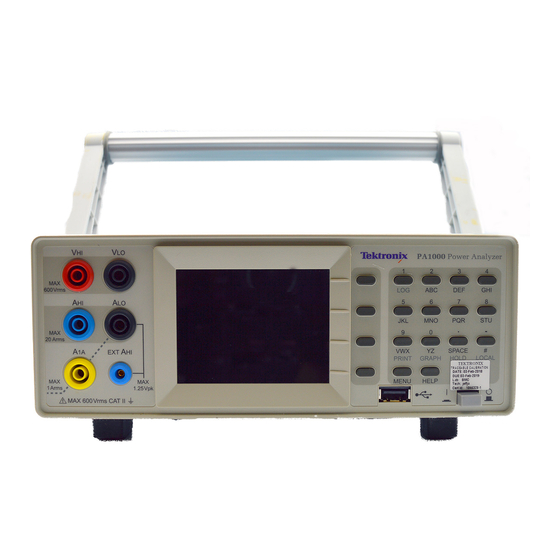
Tektronix PA1000 Power Analyzer Manuals
Manuals and User Guides for Tektronix PA1000 Power Analyzer. We have
1
Tektronix PA1000 Power Analyzer manual available for free PDF download: User Manual
Tektronix PA1000 User Manual (108 pages)
power analyzer
Brand:
Tektronix
| Category:
Measuring Instruments
| Size: 5 MB
Table of Contents
Table of Contents
7
Important Safety Information
11
General Safety Summary
11
Service Safety Summary
13
Terms in this Manual
14
Symbols and Terms on the Product
14
Compliance Information
16
EMC Compliance
16
Safety Compliance
17
Environmental Considerations
20
Preface
21
Introduction
23
Basic Features
23
Figure 1: PA1000 Power Analyzer
23
Standard Accessories
24
Optional Accessories
24
Table 1: Standard Accessories
24
Table 2: Optional Accessories
24
Service Options
25
Table 3: Service Options
25
Getting Started
26
Before You Begin - Safety
26
Power on
28
Figure 2: Initial Power-On Display
28
Controls and Connectors
29
Figure 3: PA1000 Front Panel
29
Figure 4: PA1000 Rear Panel
30
Connecting to the Product under Test
31
Figure 5: Typical PA1000 Input Connections
31
Figure 6: Breakout Box
32
Figure 7: Typical Breakout Box Connections
33
Default Measurements
34
Figure 8: Default Measurement Display
34
Figure 9: Display Soft Keys
34
Navigating the Menu System
35
Figure 10: Menu Keys
35
Data Logging
36
Figure 11: PA1000 Logged Data
37
Unit Configuration
38
The Menu System
39
Navigation
39
Modes
40
Table 4: Available Measurements Per Mode
41
Inputs
43
Graphs
45
Interfaces
46
System Configuration
46
User Configuration
48
View
48
Connecting Signals
49
Input Overview
49
To Connect a Simple Current Transformer
50
Figure 12: Current Transformer Connections
50
To Connect an External Resistive Shunt
51
Figure 13: External Resistive Shunt Connections
51
To Connect a Transducer with a Voltage Output
52
To Connect a Voltage Transformer / Transducer
53
Figure 14: Transducer with Voltage Output Connections
53
Figure 15: Voltage Transformer / Transducer Connections
54
Remote Operation
55
Overview
55
Interfacing with USB Systems
55
Interfacing with Ethernet Systems
55
Figure 16: Communication Ports
55
Interfacing with GPIB Systems
56
Status Reporting
56
Command Listing
58
IEEE 488.2 Standard Commands and Status Commands
59
Unit Information Commands
61
Measurement Selection and Reading Commands
62
Measurement Configuration Commands
63
Mode Setup Commands
65
Input Setup Commands
67
Graph and Waveform Commands
70
Interface Commands
71
System Configuration Commands
73
User Configuration Commands
75
View Commands
75
Sending and Receiving Commands
76
Communications Examples
77
Software
79
PWRVIEW PC Software
79
PA1000 Firmware Update Utility
80
Figure 17: PWRVIEW Application
80
Applications Examples
82
IEC 62301 Compliance Testing and Low-Power Standby Measurements
82
Figure 18: Laptop Charger Full-Compliance Standby Power Test with PWRVIEW Software
83
Figure 19: PA1000 Measuring 5 Mw in Front-Panel Standby Mode
84
Figure 20: Standby Power Measurement Connections
84
IEC 61000-3-2 Pre-Compliance Current Harmonics Testing
85
Figure 21: IEC 61000-3-2 Pre-Compliance Test Running on PWRVIEW Software
87
Figure 22: Connection Diagram for IEC 61000-3-2 Pre-Compliance Current Harmonics Test
88
Figure 23: Connecting a Power Analyzer for the First Time Using the PWRVIEW Software
89
Figure 24: Pre-Compliance Harmonics Test Setup
89
Figure 25: Test Environment and Other Important Information Setup
90
Figure 26: Select Load Class Based on IEC Standard
90
Figure 27: IEC 61000-3-2 Pre-Compliance Test
91
Figure 28: Table View for IEC 61000-3-2 Pre-Compliance Test
91
Figure 29: Results Summary for IEC 61000-3-2 Pre-Compliance Test
92
Figure 30: Harmonics Results with Scroll Bars for Time and Amplitude
92
Figure 31: PDF Report for IEC61000-3-2 Pre-Compliance Test
93
Specifications
94
Measurement Channel
94
Power Input
94
Mechanical and Environmental
95
Communication Ports
96
Measured Parameters
98
Table 5: Phase Measurements
98
Power Polarity
99
Table 6: Power Polarity
99
Digital Filter
100
Measurement Accuracy
100
Figure 32: Input Fuse Rating
103
Check the Fuse
104
Figure 33: Input Fuse Location
104
Fuse Replacement Procedure
104
Select the Proper Fuse
104
Appendix A: Input Fuse Replacement
103
Advertisement
Advertisement
Related Products
Tektronix PA4000 Series
Tektronix PA3000
Tektronix PSM4120
Tektronix P6131
Tektronix TriMode P7513
Tektronix P6241
Tektronix TriMode P7516
Tektronix PQA600A
Tektronix P6330
Tektronix P6209
Tektronix Categories
Test Equipment
Measuring Instruments
Amplifier
Portable Generator
Printer
More Tektronix Manuals
Login
Sign In
OR
Sign in with Facebook
Sign in with Google
Upload manual
Upload from disk
Upload from URL