
Related Manuals for TSL PAM2-3G16


Summary of Contents for TSL PAM2-3G16
- Page 1 PAM2-3G16 AUDIO MONITORING UNIT Handbook – Issue 4 Vanwall Road, Maidenhead, Berkshire, SL6 4UB - United Kingdom Telephone +44 (0)1628 676200 FAX +44 (0)1628 676299...
- Page 2 P a g e SAFETY Installation. Unless otherwise stated TSL equipment may be installed at any angle or position within an operating temperature range of 5 - 30C. All TSL equipment conforms to the EC Low Voltage Directive: EC Low Voltage Directive (73/23/EEC)(OJ L76 26.3.73)(LVD).
- Page 3 • Symptoms of the fault (to include switch setting positions, input signals etc): Packing Please ensure that the unit is well packed as all mechanical damage is chargeable. TSL recommends that you insure your equipment for transit damage. The original packaging, when available, should always be used when returning equipment.
- Page 4 Maidenhead SL6 4UB England United Kingdom Type of Equipment: Audio Monitoring Unit Model No: PAM2-3G16 Series Date CE Mark Affixed: 26/01/09 I, the undersigned, declare that the equipment specified above conforms to the quoted Directives and Standards. Place: Maidenhead, England...
- Page 5 P a g e This Page is Blank PAM2-3G16 User Handbook Issue 4...
-
Page 6: Table Of Contents
Discrete PCM 5.1 Audio 2.9.2 Dolby E, Dolby Digital and Dolby Digital Plus (Dolby version only) 2.10 Internal and External Monitoring Modes 2.11 Data and Metadata Menus 2.11.1 Dolby Metadata (Dolby version only) 2.11.2 Data Screen PAM2-3G16 User Handbook Issue 4... - Page 7 GPI connector – D15 Plug Pinout Remote Control connector/RS422 - D9 Socket Pinout Metadata - D9 Socket Pinout DIP switch configuration functions Notes Power Supply Mounting Bracket General Notes Specifications HDC-2T Audio Monitor Module Specification PAM2-3G16 User Handbook Issue 4...
-
Page 8: Introduction
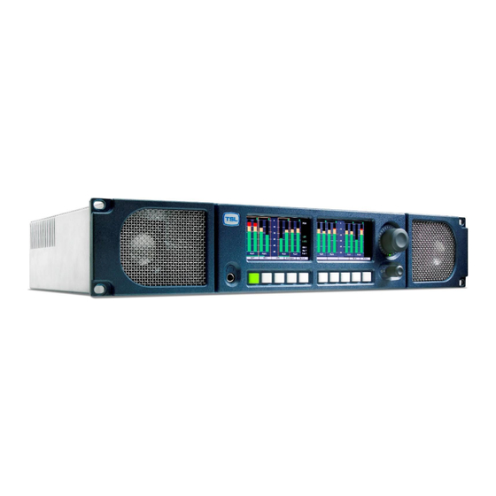
P a g e Introduction The PAM2-3G16 is a 2RU x 320mm deep Audio Monitoring Unit with two OLED displays for audio level measurement, video confidence and metadata status indication. PAM2-3G16 has been designed in conjunction with some of the worlds leading broadcasters to produce arguably the most comprehensive, intuitive and feature packed product of it’s type. - Page 9 P a g e PAM2-3G16 Hookup Schematic PAM2-3G16 User Handbook Issue 4...
- Page 10 P a g e | 10 PAM2-3G16 User Handbook Issue 4...
-
Page 11: Operation
| 11 Operation. The PAM2-3G16 is designed to be user friendly and intuitive to operate. The menus and functions will feel familiar to both users of TSL multichannel audio monitoring products and those buying a TSL solution for the first time. -
Page 12: Control And Displays
| 12 Controls and Displays PAM2-3G16’s menus and features are navigated via a multi-function encoder and a bank of ten pushbuttons. The diagrams below give an overview of the front control panel. • The left hand OLED screen displays bargraphs 1-8 in Full-screen mode and bargraphs 1-16 when Menu / Data or Video modes are activated. - Page 13 Loudness Histogram Screens when in Full-screen mode and to save User Presets when in Menu mode. • The 10th button located below the right hand OLED screen is used to toggle the Video Screen when in Full-screen mode and to navigate ‘Back’ from Menu modes. PAM2-3G16 User Handbook Issue 4...
-
Page 14: Top Level Screen Mode
P a g e | 14 Top Level Screen Mode The example below shows PAM2-3G16 in dual screen Metering Mode listening to Group 1 Pair 1 of an embedded SDI video signal. 2.2.1 Scroll to Hear Push, hold and rotate the Encoder to move the yellow ‘Scroll To Hear’ box to listen to any of the 16 embedded audio channels. -
Page 15: Dolby E Timing And Rate Information
2.2.4 Dolby E Timing and Rate Information The Data Screen of the PAM2-3G16 displays extended information about any Dolby E and Dolby Digital sources. This shows the frame rate of the Dolby encoded signal and its timing relative to a video source where available. -
Page 16: Main Menu Mode
Input Selection PAM2-3G16 ships with User Presets 1-5 programmed to instantly access SDI1, SDI2, AES, Analogue and Optical TOSLINK inputs. Selecting these presets will directly route either input signal to the bargraph display. These User Presets may be overwritten however and customised as required. -
Page 17: Aes Input
| 17 2.4.3 AES Input Optical Input – PAM2-3G16 is unique amongst rack mount audio monitoring products in that 2.4.4 it features a TOSLINK Optical Input. The Optical Input is selected via Factory Preset 5. When Optical is selected, AES channel 8 is replaced by the signal received via the Optical connector. This input may be used to connect directly to a Set Top Box, DVD or CD player and can decode Dolby Digital or Dolby Digital Plus encoded signals. -
Page 18: Monitor Menu
Pushing to select L – R enables individual selection of either Left or Right components of the 2.6.2 highlighted stereo pair (or pairs). The L – R function also enables Left and Right audio components to be swapped. The Mono mode button mono’s the selected bargraph pair 2.6.3 PAM2-3G16 User Handbook Issue 4... -
Page 19: Downmix Mode
C, Lfe, Ls, and Rs). The Downmix Mode uses the ITU-R BS.775 algorithm standard. Once the 5.1 audio components are selected and Downmixed, the selection can be stored as a User Preset to a Hotkey (see Storing User Presets) and recalled at the press of a button. PAM2-3G16 User Handbook Issue 4... - Page 20 The selection may be saved as a User Preset for instant recall (see Saving User Presets). Note; Split Mono selection uses the Assign Matrix section of the PAM2-3G16 in order to create a pair of non consequential audio channels. When a Split Mono pair is defined, the Assign Matrix represents the resultant signal selection as illustrated below.
-
Page 21: Front Switch Monitor Select Mode
| 21 Front Switch Monitor Select Mode In order to further enhance hands on operation of PAM2-3G16, an operational mode exists which enables the user to toggle between the standard front panel operation of 8 user preset recall switches below the OLED displays and direct access to up to 6 monitoring mode selector buttons. - Page 22 Lt Rt (Dolby Only) By pressing the LtRt button when PAM2-3G16 is decoding a Dolby E, D or DD+ signal, a stereo Downmix will be selected. This is the default listening/monitoring condition for a Dolby signal and is derived using the originally authored Dolby metadata thus enabling the user to hear the effect of stereo downmixing as heard by the consumer.
- Page 23 When a Dolby E, Dolby Digital or Dolby Digital Plus encoded audio pair is selected, PAM2-3G16 will automatically decode the signal into its component parts and name the stems according to the Channel Coding information carried within the Metadata. The decoded audio component bargraph is displayed on the left OLED display –...
-
Page 24: Discrete Pcm 5.1 Audio
P a g e | 24 To exit Dolby Decoding Mode, push and hold the encoder for several seconds and the PAM2-3G16 will revert to the Top Level Mode as shown below. The encoder can be rotated to move the ‘Hear Box’... -
Page 25: Dolby E, Dolby Digital And Dolby Digital Plus (Dolby Version Only)
DRC button enabling the user to hear the effect of either form of compression on the decoded signal and hence check the integrity of the audio heard by the consumer. PAM2-3G16 User Handbook Issue 4... -
Page 26: Internal And External Monitoring Modes
| 26 2.10 Internal and External Monitoring Modes The table below indicates the various monitoring modes available to PAM2-3G16 users and the audio signals presented to internal loudspeakers and external connectors when each mode is selected. Ext Fixed/Variable D25 refers to both analogue and AES multichannel 1-8 output connectors whose modes can be altered via the rear panel DIP switches. -
Page 27: Data And Metadata Menus
Setup window. By selecting E prg# the user may scroll through Dolby E programme numbers 1 to 8 and select the appropriate programme number. This setting may be saved as part of a user preset. PAM2-3G16 User Handbook Issue 4... -
Page 28: Data Screen
Mode. When the Loudness feature is activated, the Data selection will toggle between Bargraph/Data/Loudness. The Data Screen provides up to 6 fields of feedback regarding the signal being monitored and the operational status of PAM2-3G16. State: The current User Preset name and number Source: The selected input signal and channel... -
Page 29: Setup Menu 1 And
Setup Menu 1 includes options for different Scales, Reference Levels, Peak Hold, Dolby E programme, Dolby E Video compensation delay, Video Window and Audio delay. By highlighting and selecting a parameter, the user can scroll through the available options and tailor PAM2-3G16 to suit their needs . -
Page 30: Dolby E Video Delay (Dolby Version Only)
The Hold parameter activates a peak hold indication when switched on. 2.12.2 Dolby E Video Delay The PAM2-3G16 features a 1 frame (40 ms) video delay setting which can be inserted into the Downconverted video display to compensate for the latency caused by decoding a Dolby E signal. If selected and activated, the delay will be switched into the video signal path automatically when a Dolby E input signal is detected and decoded. -
Page 31: Audio Delay
| 31 2.12.3 Audio Delay The TSL PAM family of audio monitoring units is unique in that they feature the ability to insert up to 250ms of delay into the audio monitoring signal path (headphone, internal speaker or variable level outputs). - Page 32 This setup may suit applications such as MCR or QC Suites where specific programme content occasionally requires the attention of full range or 5.1 listening or when two or more PAM2-3G16 operators share a common external speaker system.
- Page 33 | 33 2.12.11 Energy Saver Mode (ScrnSave) PAM2-3G16 features an energy saving mode which dims the OLED displays after a defined period of time when activated. The ScrnSave button within Setup2 menu access 4 preset time settings after which the OLED displays will dim, reactivated once a button is pressed or an encoder turned by one click.
-
Page 34: Assign Matrix
AES or Analogue connections (exclusively). The outputs represent the 6 surround channels of a 5.1 programme and once the matrix is ‘activated’ are displayed as 6 bargraphs on the left OLED. Standard PAM2-3G16 monitoring modes can be used to derive a Downmix, solo individual channels or route audio to external surround loudspeakers. - Page 35 (by using Downmix) or for applications such as ‘Solo in Place’ and LCR monitoring. It is important to note that the Assign Matrix will remain active when associated with a User Preset state until the Inactive button is pressed. PAM2-3G16 User Handbook Issue 4...
-
Page 36: Loudness Measurement
ITU-R BS1770 Loudness Setup menu is accessed from the Main Menu. PAM2-3G16 aims to provide the user with a set of tools which comply with the recommendations of both the ATSC (A85) and EBU (R128) Loudness committees whilst giving the flexibility to tailor operation to suit local requirements. -
Page 37: Target Level, Limit Threshold And Red Line Alarm
PAM2-3G16 will continue to measure the Loudness of the highlighted audio components. In this mode of operation PAM2-3G16 does not make the assumption that the audio signals are present in the correct SMPTE channel order for 5.1 sound – by selecting the channel components individually, non SMPTE order 5.1 audio can be chosen and measured. - Page 38 The Limit Value at which a Loudness value ‘red lines’ can be set at up to +6 LU above the Target Value. At the point at which the ‘Red Line’ limit is reached, PAM2-3G16 triggers an output GPI via the D15 rear connector. This can be used for external Alarm notification and/or to control a third party Loudness control device.
-
Page 39: Start, Stop And Reset Triggers
| 39 2.14.3 Start, Stop and Reset Triggers In order that Loudness measurement is targeted towards specific programme content, PAM2-3G16 is equipped with the ability to Start and Stop (pause) measurement cycles. These functions can either be triggered manually from the on screen button or from a GPI via the D15 connector at the rear of the unit. - Page 40 The diagram below shows a programme Histogram displaying a Target level measurement with a Limit level set at +4 LU which is being exceeded at three points PAM2-3G16 User Handbook Issue 4...
-
Page 41: Preset Standard Rules
ALL is the default condition and is used in normal operation. By definition, when Preset Standard is set to ALL, the PAM2-3G16 operates as usual and is oblivious to changes to input signal types, auto sensing and functions as normal. - Page 42 P a g e | 42 PAM2-3G16 User Handbook Issue 4...
-
Page 43: Auxiliary Input Mixer
The Auxiliary Input Mixer provides the ability to select exclusively from either an Analogue or AES audio input and to mix that audio signal into the PAM2-3G16 monitoring output buss. The resultant signal can be heard through either headphone or the loudspeaker outputs. The selected auxiliary... - Page 44 Aux Level; The Aux Level control enables the user to trim the level of the selected Aux Input between ‘Off’ and +12dB of gain with respect to the signal monitored by the main PAM2-3G16 monitoring function. The level adjustment is graduated in incremental steps as the user pushes and rotates the encoder control.
- Page 45 Format the memory card to FAT16 (or FAT as described in Windows XP). PAM2-3G16 operating software and occasional Dolby CAT552 updates will be sent to you by TSL in the form of a ZIP file or may be downloaded from the Product Support area at www.tsl.co.uk. These files must be extracted directly to the memory card in order to construct the correct file structure for upload.
-
Page 46: Gpi Application
The optional Dolby CAT552 module can be updated using a similar procedure that described for the PAM2-3G16 operating system. From Setup 2 select Cat 552 to review and update the Dolby card operating software. Features such as Dolby Digital Plus decoding may be added to the CAT552 module via the update procedure. -
Page 47: Gpi Connectivity
Note that the +5V power from this connector is intended to drive a "1-of-N" LED. If multiple LED’s are to be used simultaneously, then a small external supply will be needed. An internal resistor within the PAM2-3G16 prevents the +5V rail from being shorted but limits the current available. PAM2-3G16... -
Page 48: Preset Memories
P a g e | 48 2.20 Preset Memories PAM2-3G16 features 5 Factory and 24 User Programmable Presets, for save and instant recall of default and favourite settings. 2.20.1 Factory Presets Rotating the Encoder counter-clockwise activates the Factory Preset window in the right hand OLED screen. - Page 49 To recall a User Preset which isn’t stored on Preset Recall buttons 1-8, rotate the Encoder clockwise to activate the User Preset window in the right hand OLED screen. Highlight and select to recall a User Preset from locations U01 to U24. PAM2-3G16 User Handbook Issue 4...
- Page 50 For unbalanced AES I/O connectivity an optional BNC breakout cable, CAB-D25-BNC, is available from TSL or your local reseller. When used in conjunction with PAM2-3G16, DIP switch 2 (AES Impedance) must be switched to the 75 ohm position. For more information please refer to section 3.5 of this handbook.
- Page 51 A7+ (7.1) A7- (7.1) Ground A6+ (RS) A6- (RS) Ground A5+ (LS) A5- (LS) Ground A4+ (LFE) A4- (LFE) Ground A3+ (Centre) A3- (Centre) Ground A2+ (FR) A2- (FR) Ground A1+ (FL) A1- (FL) Ground PAM2-3G16 User Handbook Issue 4...
- Page 52 Analogue Input Connector – D25 Socket Pinout on unit, Plug on mating cable. D 25 SOCKET AUDIO IN ON AMU PIN NO FUNCTION A6R+ A6R+ Ground A6L- A6L- Ground A5R+ A5R- Ground A5L+ A5L- Ground A4R+ A4R- Ground A4L+ A4L- Ground A3R+ A3R- Ground A3L+ A3L- Ground PAM2-3G16 User Handbook Issue 4...
- Page 53 Optional AES breakout cable CAB-D25-BNC-2 is available from TSL Sales (+44 1628 676200) and provides BNC Socket to D25 connectivity. Please note that when using PAM2-3G16 with unbalanced AES audio connections that the 75/110 ohm DIP Switch must be selected prior to use.
- Page 54 GPI 5 – Preset 3 GPI 4 – Preset 2 GPI 3 – Preset 1 GPI 2 – CUT GPI 1 – DIM Remote Control Connector/ RS 422 - D9 Socket This is wired for RS422 slave operation. CONTROL PAM2-3G16 User Handbook Issue 4...
- Page 55 FUNCTION Video aspect ratio (16:9 Up/4:3 Dn) AES Impedance (75R Up/110R Dn) Internal speaker mute - Up Analogue variable – Up AES variable - Up XLR fixed Out (when set) Not Used Composite Up/SDI Dn PAM2-3G16 User Handbook Issue 4...
- Page 56 Power Supply Mounting Bracket PAM2-3G16 is powered via a supplied external 12 volt, DC supply. For your convenience a rear panel mounting bracket is also included with the product in order that the power supply can be held in place.
- Page 57 General Notes Please note that some American equipment has the function of the XLR pins 2 & 3 reversed. TSL product is wired to the European standard The screw locks on the D25 connectors use UNC 4-40 standard threads. PAM2 - 3G8 Technical Specifications...
- Page 58 Performance Response 70Hz to 20KHz Electrical Distortion Better than 0.1% Hum and noise Better than -80dB >98dB at 0.6 m Amplifier Output 40 watts total power output Digital Sample Rate 32 to 48KHz auto select PAM2-3G16 User Handbook Issue 4...
- Page 59 Composite SD (Down-converted when input is HD) Format: PAL or NTSC according to standard on SDI input Impedance: 75 Amplitude: 1V p-p ±5% Output 3 - Optional SDI version of image on composite output Impedance: Amplitude: 800mV p-p ±10% PAM2-3G16 User Handbook Issue 4...
- Page 60 10 to 40W (4) per channel into depending on input power supply GPI inputs Connector type: Header to 9-way D-type plug Control Connector type: Header for current AMU-1 operator control board Connector type: Header, serial bus for future operator control/display panels PAM2-3G16 User Handbook Issue 4...
Need help?
Do you have a question about the PAM2-3G16 and is the answer not in the manual?
Questions and answers