Table of Contents
Advertisement
Quick Links
SERVICE MANUAL
AUDIO/VIDEO CONTROL RECEIVER
TV/CATV/DBS
VCR
DVD
DVD MUILTI
CD
TAPE/MD
TV/DBS
PHONO
FM/AM
VCR
ANALOG/DIGITAL
SLEEP
SURROUND
CENTER
1
2
3
ON/OFF
MENU
MENU
TEST
REAR-L
SURROUND
MODE
4
5
6
ENTER
ENTER
CD-DISC
EFFECT
REAR-R
7
8
9
/P
SOUND
SEA MODE
SUBWOOFER
10
0
+10
RETURN
FM MODE
100+
AUDIO/
TV/VCR
MENU
CATV/DBS
SET
TEXT
EXIT
DISPLAY
STANDBY
TV VOL
CHANNEL
VOLUME
STANDBY/ON
TV/VIDEO
VCR
TAPE/MD
MUTING
CONTROL
PLAY
/REW
FF/
PTY
PTY SEARCH
PTY
REC
STOP
PAUSE
PHONES
COMPULINK
Remote
RM-SRX7000R
REMOTE CONTROL
Contents
Safety precautions ---------------- 1-2
Disassembly method ------------- 1-3
RX-7000RBK
RX-7000R AUDIO/VIDEO CONTROL RECEIVER
SURROUND ON/OFF
EON
TA/NEWS/INFO
PTY SEARCH
DISPLAY MODE
THEATER
LIVE CLUB
DANCE CLUB
HALL
PAVILION
INPUT
DSP MODE
SEA MODE
ANALOG/DIGITAL
FM/AM TUNING
TUNER PRESET
TUNER/SEA MEMORY
FM MODE
SPEAKERS
BALANCE/SURROUND
1
2
ADJUST
SEA ADJUST
SETTING
SOUND SELECT
BASS BOOST ONE TOUCH OPERA TION
SOURCE NAME
INPUT ATT.
ENHANCED COMPULINK CONTROLSYSTEM
This service manual is printed on 100% recycled paper.
COPYRIGHT
2000 VICTOR COMPANY OF JAPAN, LTD.
E
EN
MASTER VOLUME
D I G I T A L
-
+
DVD
CD
TV SOUND/DBS
PHONO
VCR
TAPE/MD
FM
AM
MULTI JOG
SOURCE SELECTOR
Adjustment method --------------- 1-9
Description of major ICs --------- 1-10
RX-7000RBK
RX-7000RBK
Area Suffix
Continental Europe
Northern Europe
D I G I T A L
No.20846
Jul. 2000
1-1
Advertisement
Chapters
Table of Contents

Related Manuals for JVC RX-7000RBK


Summary of Contents for JVC RX-7000RBK
- Page 1 RX-7000RBK RX-7000RBK SERVICE MANUAL AUDIO/VIDEO CONTROL RECEIVER RX-7000RBK Area Suffix Continental Europe Northern Europe TV/CATV/DBS DVD MUILTI TAPE/MD TV/DBS PHONO FM/AM ANALOG/DIGITAL SLEEP SURROUND CENTER ON/OFF MENU MENU TEST REAR-L SURROUND MODE ENTER ENTER CD-DISC EFFECT REAR-R SOUND SEA MODE...
-
Page 2: Safety Precautions
RX-7000RBK Safety Precautions 1. This design of this product contains special hardware and many circuits and components specially for safety purposes. For continued protection, no changes should be made to the original design unless authorized in writing by the manufacturer. -
Page 3: Disassembly Method
RX-7000RBK Disassembly method Top cover Removing the top cover (See Fig.1) Remove the four screws A attaching the top cover on both sides of the body. Remove the three screws B on the back of the body. Remove the top cover from behind in the direction of Fig.1... - Page 4 RX-7000RBK Removing each board connected to the rear side of the main board CN202 (See Fig.5 to 9) Prior to performing the following procedure, remove the top cover and the rear panel. Cut off the tie band fixing the harness.
- Page 5 RX-7000RBK Removing the main board / regulator Relay board 1 CN821 CN704 CN901 board (See Fig.10 to 12) Relay board 2 Prior to performing the following procedure, remove the top cover and the rear panel. Power supply Main board board...
- Page 6 RX-7000RBK Removing the amplifier board Relay board 1 CN821 CN704 CN901 (See Fig.10 and 14) Relay board 2 Prior to performing the following procedure, remove the top cover. Power supply Main board board CN400 Cut off the four tie bands fixing the harnesses.
- Page 7 RX-7000RBK Removing the power supply board (See Fig.17 and 18) Prior to performing the following procedure, remove the top cover and the front panel. Remove the one nut attaching the headphone jack of the power supply board on the front side of the body.
- Page 8 RX-7000RBK Removing the operation switch board (See Fig.21 to 23) Front panel Prior to performing the following procedure, remove the top cover, the front panel assembly and the system control board. Remove the six screws R attaching the operation switch board on the back of the front panel.
-
Page 9: Adjustment Method
RX-7000RBK Adjustment method Power amplifier section Adjustment of idling current Measurement location TP781 Adjustment part VR787(Lch) , VR788(Rch) Attention This adjustment does not obtain a correct adjustment value immediately after the amplifier is used (state that an internal temperature has risen). -
Page 10: Description Of Major Ics
RX-7000RBK Description of major ICs AK4527 (IC601) : A/D,D/A Converter 1.Pin layout VREFL SDOS RIN+ OCKS RIN- LIN+ BCLK LIN- LRCK ROUT1 SDTI1 LOUT1 SDTI2 ROUT2 SDTI3 LOUT2 SDTO ROUT3 DAUX LOUT3 2.Block diagram Audio LIN+ LIN- RIN+ RIN- LRCK... - Page 11 RX-7000RBK 3. Pin function (1/2) AK4527(1/2) Pin name Function SDTO Source select pin SDOS "L" : Internal ADC output, "H" : DAUX input ORed with serial control register if P/S="L". OCKS MCKO Clock frequency select pin "L" : MCLK, "H" : MCLK/2.
- Page 12 RX-7000RBK 3.Pin function (2/2) AK4527(2/2) Pin Name Function VREFL Negative voltage reference Input pin, AVSS VCOM Common voltage output pin,AVDD/2 Large external capacitor around 2.2uF is used to reduce power-supply noise VREFH Positive voltage reference input pin,AVDD AVDD Analog power supply pin...
- Page 13 RX-7000RBK BU2092(IC402,IC405):LED Controller 1.Terminal Layout DATA CLOCK CONTROL CIRCUIT 2.Pin Function Symbol Function Pin No. Connect to GND DATA Serial Data input CLOCK Shift Clock of Data Latch Clock of Data 5~16 Q0~Q11 Parallel Data Output Latch Data OUTPUT ON OFF...
- Page 14 RX-7000RBK LA1838(IC102): FM AM IF AMP&detector, FM MPX Decoder 1. Block Diagram DECODER RF.AMP ANIT-BIRDIE MUTE BUFF STEREO P-DET AM IF PILOT 384KHz COMP S-METER AM/FM S-CLRVE S-METER IF-BUFF TUNING STEREO DRIVE DRIVE FM IF 2. Pin Function Symbol Function...
- Page 15 RX-7000RBK LC72136N (IC121) : PLL Frequency synthesizer 1. Pin layout FM/AM LPFOUT LPFIN CLOCK FM/ST/VCO FMIN AM/FM AMIN IFCONT SDIN IFIN 2. Block diagram Phase Reference Detector Driver Charge Pump Swallow Counter Swallow Counter 1/16,1/17 4bit 1/16,1/17 4bit Unlock Detector...
- Page 16 RX-7000RBK LC7522 (IC451) : SEA Control 1.Pin layout 2.Block diagram – – 26 IN2 27 IN1 Network Network Resistor Resistor Latch Circuit Control Shift Resistor 12 TEST2 TEST1 3.Pin function Pin No. Symbol Function Power Supply terminal for Audio signal +7V(typ) Power Supply terminal 0V Power Supply terminal for Audio signal.
- Page 17 RX-7000RBK MN101C15FDE (IC401) : System control micon 1. Pin layout 2. Pin function Functions Functions Symbol Symbol VIDEO3 Ground VIDEO 3 signal terminal VIDEO4 DVD S/C signal select terminal VIDEO 4 signal terminal DVD-S/C S.MUTE VCR1 S/C signal select terminal...
- Page 18 RX-7000RBK MB90088PF-131 (IC203) : On screen display controller 1.Terminal layout AVss YOUT VOUT AVcc COUT FSCO VBLK SCLK TEST VOC0 HSYNC VOC1 VSYNC VOC2 EXHSYN EXVSYN 2.Block diagram Serial Input Each Control, Data SCLK Control EXHSYN H/V Separate EXVSYN VOUT...
- Page 19 RX-7000RBK 3.Pin functions (MB90088PF-131) Symbol I/O Function Brightness signal Input terminal for Superinpause indication Composite video signal input terminal for Superinpause indication Contrast signal input terminal for Superinpause indication Analog power supply terminal AVcc Color (Brightness) signal output terminal IOUT...
- Page 20 RX-7000RBK MN173222DG(IC400):FL Display & Operation switch control 1.Pin layout 2.Key matrix KEY OUT 4 KEY OUT 2 KEY OUT 3 KEY OUT 5 KEY OUT 0 KEY OUT1 KEY IN 0 SEA ADJUST POWER ANALOG/ DISPLAY MODE ONE TOUCH FM/AM TUNING...
- Page 21 RX-7000RBK TC9162AN (IC321): Analog switch 1.Function Switch to On/Off of S1 to S8 by control of LSI. 2.Terminal Lay out & Block Diagram TC9162N L-S1 R-S1 COM-1 COM-1 SHIFT SHIFT RESISTOR RESISTOR & & LATCH LATCH COM-2 COM-2 COM-3 COM-3...
- Page 22 RX-7000RBK TC9446F-014(IC631):Digital signal processor for dolby digital / DTS audio decode Pin No. Symbol Function Reset signal input terminal (L:reset H:Operation usually) Microcomputer interface mode selection input terminal (L:serial H:IC bus) MIMD Microcomputer interface chip select input terminal MICS Microcomputer interface latch pulse input...
- Page 23 RX-7000RBK TC9459F (IC331,IC332,IC333) : Electronic volume control 2. Block diagram 1.Pin layout L-OUT R-OUT L-OUT R-OUT 50k / L-IN R-IN 91 STEP L-ch L-1N L-LD1 R-ch R-IN R-LD1 L-LD2 R-LD2 Same as L-ch L-LD1 R-LD1 L-A-GND R-A-GND Circuit L-LD2 R-LD2...
- Page 24 RX-7000RBK UPD784215AGC103(IC671):UNIT CPU 1.Pin layout 2.Pin function Pin No. Symbol Function Non connect Power supply terminal Connecting the crystal oscillator for system main clock Connecting the crystal oscillator for system main clock Connect to GND Connecting the crystal oscillator for system sub clock...
- Page 25 RX-7000RBK SAA6588 (IC191) : RDS Detector 2.Pin Function 1.Terminal Layout Symbol Function Multi-path rectifier output Non connect Test control input pin SCOUT Oscillator output OSCO OSCO Vref Oscillator input OSCI OSCI Digital ground (0V) VSSD Digital power supply (5V) VDDD...
- Page 26 RX-7000RBK <<MEMO>> 1-26...
-
Page 27: Block Diagrams
RX-7000RBK Block diagrams Power amplifier & Audio I/O section System control & Video I/O section CN701 CN702 CN711 CN712 DVD IN TV/BS J241 VCR1 OUT J201 TV/BS IN VCR1 IN J202 VCR1 J242 VCR1 IN MONITOR J203 MONITOR J243 CN202... - Page 28 RX-7000RBK RX-7000RBK DSP Section DIGITAL IC621 IC622 J601 IC601 OPTICAL D/A,A/D IN 1,2 SELECTOR Converter UN661 LOUT2 IC611 UN662 CDTI CLOCK ROUT2 CDTO X631 CCLK 24.576MHz OPTICAL SDTI0~3 IC501 UN663 IC511 LRCLK BCLK IC631 SURROUND SELECT1~4 IC581 SWITCH IC591 IC602...
- Page 29 TH71 POWER QAD0095-4R7 1SR139 1SR139 470/16 CN51 CN71 CN61 1SR139 MTZ6.2JC MTZ33JC 22/50 SHUT EP51 330P 330P Parts are safety assurance parts. When replacing those parts make SHEET MODEL sure to use the specified one. RX-7000VBK / RX-7001PGD / RX-7000RBK...
- Page 30 CN601 REAR_L SLCH R1333 100K CN201 CN241 AUDIO SIGNAL CENTER SIGNAL Parts are safety assurance parts. SHEET MODEL When replacing those parts make TUNER SIGNAL FRONT SIGNAL sure to use the specified one. RX-7000VBK / RX-7001PGD / RX-7000RBK SURROUND SIGNAL...
- Page 31 R994 R735 D751 1SS133 R817 3.9K R995 R747 CN931 CN961 CN704 CN901 D811 R811 1SS133 SHEET MODEL AUDIO SIGNAL Parts are safety assurance parts. When replacing those parts make RX-7000VBK / RX7001PGD / RX-7000RBK sure to use the specified one.
- Page 32 Q1892 sure to use the specified one. D1802 2SC2389S( S,E) R1892 1SS133 2.7K D1872 C1814 1SS133 0.01MY R1896 SURROUND SIGNAL Q1852 2SD2390LD/OPY R1852 C1812 CENTER SIGNAL Q1806 C1852 2SA1038S/S R1806 R1822 C1816 2.2/50 SHEET MODEL RX-7000VBK / RX-7001PGD / RX-7000RBK...
- Page 33 CN311 CN312 CN313 Parts are safety assurance parts. SHEET When replacing those parts make MODEL R1250 sure to use the specified one. R1251 RX-7000VBK / RX-7001PGD / RX-7000RBK J1250 R1252 CD/AUDIO SIGNAL TUNER SIGNAL R1253 R1254 SURROUND SIGNAL J1251 D1252 MTZ6.2JC...
- Page 34 C219 VOUT1 Q200 R213 470/6.3 SCLK KTA1267/YG C277 C220 L200 Q241 KTA1267/YG CN204 CN242 CN240 CN205 CN243 Parts are safety assurance parts. SHEET MODEL When replacing those parts make sure to use the specified one. RX-700VBKU / RX-7001PGD / RX-7000RBK...
- Page 35 RX-7000RBK FL Display & System control section CN412 4.7/50 C410 C409 4.7/50 DI400 QLF0071-001 DVD_LED D430 SLR-342VC TV_LED D431 SLR-342VC C408 VCR1_LED D432 SLR-342VC R412 C407 Q413 C494 KRA107M 0.022 C412 100/6.3 X400 AM_LED LED_DATA D435 SLR-342VC 6MHz LED_CLK IC402...
- Page 36 100/6.3 0.01 C689 C690 0.01 100/6.3 CN681 CN687 AUDIO SIGNAL SHEET SURROUND SIGNAL Parts are safety assurance parts. MODEL When replacing those parts make CENTER SIGNAL sure to use the specified one. RX-7000VBK / RX-7001PGD / RX-7000RBK FRONT SIGNAL 2-10...
- Page 37 RX-7000RBK Tuner section C129 0.001 RF101 C128 QAU0119-001 0.47/50 C134 0.0022 C137 C117 L111 C118 C133 22/16 C156 0.001 R157 Q103 C161 2SC461/BC 10/16 D129 R132 2.7K C162 1SS133 R103 10/16 R158 2.7K R146 4.7K C126 100P Q102 C139 R109 2SC535/BC 0.039...
-
Page 38: Printed Circuit Boards
RX-7000RBK RX-7000RBK Printed circuit boards Power amp. & Power spply board Power mp. & Power pply bo rd CN954 FW963 CN951 B2174 R954 R953 Q711 Q712 B2321 B2175 R952 R951 FW961 Q703 Q701 Q702 Q704 B2407 R958 R955 C705 C706... - Page 39 RX-7000RBK Main board B200 B134 Q932 D934 D933 Q931 C1379 Q933 B102 B169 C1380 B168 B167 B153 B166 R1380 B157 B152 D865 R865 FL391 C865 R855 C811 C1391 D855 B302 B156 B155 B515 R1372 Q801 B516 ST931 C855 B517 B341...
- Page 40 RX-7000RBK RX-7000RBK Input / output board C253 CN204 CN242 CN244 R1201 CN202 R241 C242 R200 B3137 C240 R250 C261 CN206 CN252 R207 R253 CN205 R1200 C260 C254 C267 C201 C241 R240 R218 J1201 C210 C245 R243 R1217 IC242 R1206 R1207...
- Page 41 RX-7000RBK FL Display & System control board FL Display & System control board 2-15...
- Page 42 RX-7000RBK RX-7000RBK DSP board Tuner board Forward side Q601 CN687 CN681 C681 C684 C690 IC672 R669 AT101 IC681 R2500 Q672 C2500 X671 Q674 R686 Q112 K622 R664 C603 C604 B105 C662 C2588 D124 K620 IC683 R2558 R663 R2557 [DOM] R661...
-
Page 43: Parts List
RX-7000RBK PARTS LIST RX-7000RBK * All printed circuit boards and its assemblies are not available as service parts. Area suffix E ----------- Continental Europe EN ------------ Northern Europe - Contents - Exploded view of general assembly and parts list Electrical parts List... - Page 44 RX-7000RBK <<MEMO>>...
- Page 45 RX-7000RBK Exploded view of general assembly and parts list Block No. SEA board SEA board Tuner Audio board board V-Audio board Video DSP board board Center tone Center tone board S-Video Pre AMP. Pre AMP. board board Main board Main board...
- Page 46 RX-7000RBK RX-7000RBK Parts list (General assembly) Parts list (General assembly) Block No. M1MM Block No. M1MM Item Parts number Parts name Q'ty Description Area Item Parts number Parts name Q'ty Description Area LV10018-032A FRONT PANEL LV30076-001A PROTECTOR VJD5429-001SS JVC MARK...
- Page 47 RX-7000RBK Electrical parts list (Main board) Block No. 01 Item Remarks Parts number Parts name Area Item Parts number Parts name Remarks Area FW881 QUM133-26DGZ4 PARA RIBON WIRE C 821 QEHR1EM-107Z E.CAPACITOR 100MF 20% 25V FW931 QUM137-16DGZ4 PARA RIBON WIRE...
- Page 48 RX-7000RBK Electrical parts list (Main board) Block No. 01 Item Remarks Item Remarks Parts number Parts name Area Parts number Parts name Area C1314 QETN1HM-475Z E CAPACITOR 4.7MF 20% 50V D 871 MTZJ10C-T2 Z.DIODE C1315 QETN1EM-476Z E CAPACITOR 47MF 20% 25V...
- Page 49 RX-7000RBK Electrical parts list (Main board) Block No. 01 Item Remarks Parts number Parts name Area Item Parts number Parts name Remarks Area R 752 QRJ146J-100X UNF.C RESISTOR 10 5% 1/4W R 914 QRE141J-823Y C RESISTOR 82K 5% 1/4W R 753 QRJ146J-100X UNF.C RESISTOR...
- Page 50 RX-7000RBK (Main board) Electrical parts list Block No. 01 Item Parts number Parts name Remarks Area R1386 QRE141J-104Y C RESISTOR 100K 5% 1/4W R1389 QRZ9005-680X F.RESISTOR 68 1/4W R1390 QRZ9005-680X F.RESISTOR 68 1/4W R1391 QRE141J-472Y C RESISTOR 4.7K 5% 1/4W...
- Page 51 RX-7000RBK (Front board) Electrical parts list Block No. 02 Item Remarks Item Remarks Parts number Parts name Area Parts number Parts name Area C 400 QEKC1HM-475Z E.CAPACITOR 4.7MF 20% 50V C1479 QCS31HJ-331Z C CAPACITOR 330PF 5% 50V C 401 QEKC0JM-107Z E.CAPACITOR...
- Page 52 RX-7000RBK (Front board) Block No. 02 Electrical parts list Item Parts number Parts name Remarks Area Item Parts number Parts name Remarks Area Q 442 KRA107M-T D.TRANSISTOR R 481 QRE141J-221Y C RESISTOR 220 5% 1/4W Q 488 KRA107M-T D.TRANSISTOR R 482...
- Page 53 RX-7000RBK (Front board) Electrical parts list Block No. 02 Item Remarks Parts number Parts name Area S 415 QSW0683-001Z PUSH SWITCH (S.SELECT) S 416 QSW0683-001Z PUSH SWITCH (TUNING) S 417 QSW0683-001Z PUSH SWITCH (PRESET) S 418 QSW0683-001Z PUSH SWITCH (MEMORY)
- Page 54 RX-7000RBK (Input board) Electrical parts list Block No. 03 Item Remarks Item Remarks Parts number Parts name Area Parts number Parts name Area C 201 QETN1HM-475Z E CAPACITOR 4.7MF 20% 50V C 319 QCF31HZ-223Z C CAPACITOR .022MF +80:-20% C 202...
- Page 55 RX-7000RBK (Input board) Block No. 03 Electrical parts list Item Parts number Parts name Remarks Area Item Parts number Parts name Remarks Area CN312 QGB2510K1-09 CONNECTOR R 242 QRE141J-750Y C RESISTOR 75 5% 1/4W CN313 QGB2510K1-12 CONNECTOR R 243 QRE141J-750Y...
- Page 56 RX-7000RBK (Input board) Block No. 03 Electrical parts list Item Parts number Parts name Remarks Area R 353 QRZ9005-680X F.RESISTOR 68 1/4W R 354 QRZ9005-680X F.RESISTOR 68 1/4W R 355 QRE141J-471Y C RESISTOR 470 5% 1/4W R 356 QRE141J-471Y C RESISTOR...
- Page 57 RX-7000RBK (AC supply board) Block No. 04 Electrical parts list Item Parts number Parts name Remarks Area Item Parts number Parts name Remarks Area QCZ9019-472 C.CAPACITOR 4700PF C1705 QCS11HJ-100 C CAPACITOR 10PF 5% 50V C 51 QFN32AK-472Z M.CAPACITOR 4700PF 10% 100V...
- Page 58 RX-7000RBK (AC supply board) Electrical parts list Block No. 04 Item Remarks Item Remarks Parts number Parts name Area Parts number Parts name Area D 704 1SS133-T2 SI DIODE Q 808 KRC109M-T D.TRANSISTOR D 805 1SS133-T2 SI DIODE Q 809 KRC109M-T D.TRANSISTOR...
- Page 59 RX-7000RBK (AC supply board) Block No. 04 Electrical parts list Item Remarks Item Parts number Parts name Remarks Area Parts number Parts name Area R 734 QRE141J-101Y C RESISTOR 100 5% 1/4W R1825 QRE141J-332Y C RESISTOR 3.3K 5% 1/4W R 941...
- Page 60 RX-7000RBK (AC-3 board) Electrical parts list Block No. 05 Item Remarks Item Remarks Parts number Parts name Area Parts number Parts name Area C 601 NCB31HK-102X C CAPACITOR CN687 QGB1214K3-12W CONNECTOR C 602 NCB31HK-102X C CAPACITOR C2500 NEA71CM-226X E.CAPACITOR C 603 NEA70JM-476X E.CAPACITOR...
- Page 61 RX-7000RBK (AC-3 board) Block No. 05 Electrical parts list Item Remarks Item Remarks Parts number Parts name Area Parts number Parts name Area C2577 NEA71HM-225X E.CAPACITOR K 601 NQR0269-007X FERRITE BEADS C2578 NEA71HM-225X E.CAPACITOR K 611 NQR0269-007X FERRITE BEADS C2579...
- Page 62 RX-7000RBK (AS-3 board) Electrical parts list Block No. 05 Item Remarks Parts number Parts name Area Item Parts number Parts name Remarks Area R 642 NRSA63J-103X MG RESISTOR R2524 NRSA63J-102X MG RESISTOR R 643 NRSA63J-101X MG RESISTOR R2525 NRSA63J-102X MG RESISTOR...
- Page 63 RX-7000RBK Electrical parts list Block No. 05 (AC-3 board) Item Parts number Parts name Remarks Area R2595 NRSA63J-102X MG RESISTOR R2596 NRSA63J-102X MG RESISTOR R2597 NRSA63J-104X MG RESISTOR R2598 NRSA63J-104X MG RESISTOR UN661 GP1FA550RZ OPT RECEIVER UN662 GP1FA550RZ OPT RECEIVER...
- Page 64 RX-7000RBK (Tuner board) Block No. 06 Electrical parts list Item Remarks Item Parts number Parts name Remarks Area Parts number Parts name Area AT101 QNB0014-001 ANT TERMINAL Q 103 2SC461/BC/-T TRANSISTOR C 101 NCB21HK-103X C CAPACITOR Q 111 KTC3199/GL/-T TRANSISTOR...
- Page 65 RX-7000RBK Packing materials and accessories parts list Block No. Block No. A1,A3,A4 A7,A10 (Packing) Parts list Block No. M2MM Item Parts number Parts name Q'ty Description Area LV30044-0D1A CARTON BOX LV20039-002A PACKING PAD LV20040-001A PACKING PAD QPC06507015P POLY BAG QPA02503505P...
- Page 66 RX-7000RBK RX-7000RBK VICTOR COMPANY OF JAPAN, LIMITED AUDIO & COMMUNICATION BUSINESS DIVISION PERSONAL & MOBILE NETWORK B.U 10-1,1Chome,Ohwatari-machi,Maebashi-city,371-8543,Japan Printed in Japan 1-27 No.20846 2000 07(O)
- Page 67 AUDIO/VIDEO CONTROL RECEIVER AUDIO/VIDEO-RECEIVER MIT STEUEREINHEIT AMPLI/TUNER DE COMMANDE AUDIO/VIDEO GEINTEGREERDE AUDIO/VIDEO-VERSTERKER RECEPTOR DE CONTROL DE AUDIO/VÍDEO RICEVITORE DI CONTROLLO AUDIO/VIDEO RX-7000RBK TV/CATV/DBS DVD MUILTI TAPE/MD TV/DBS PHONO FM/AM ANALOG/DIGITAL SLEEP SURROUND CENTER ON/OFF MENU MENU SURROUND TEST REAR-L MODE...
- Page 68 È possibile il controllo remoto dell’alimentazione. Per I’ltalia: “Si dichiara che il questo prodotto di marca JVC è conforme alle prescrizioni del Decreto Ministeriale n.548 del 28/08/95 pubblicato sulla Gazzetta Ufficiale della Repubblica Italiana n.301 del 28/12/95.”...
- Page 69 Minstens 15 cm tussenruimte Espacio de 15 cm o más Front 15 cm di distanza o più Vorderseite Avant Voorkant RX-7000RBK Frente Davanti Wall or obstructions Wand oder Hindernisse Mur, ou obstruction Stand height 15 cm or more Wand of meubilair Standhöhe 15 cm oder mehr...
-
Page 70: Table Of Contents
Searching for a Disc (Only for the CD player) ......42 Entering the Disc Information ..........43 Receiving Radio Broadcasts ......19 Operating JVC’s Audio/Video Components ... 45 Tuning in Stations Manually ............ 19 Using Preset Tuning ..............19 Operating Audio Components ..........45 Selecting the FM Reception Mode ........... -
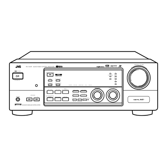
Page 71: Parts Identification
Parts Identification Become familiar with the buttons and controls on the receiver before use. Refer to the pages in parentheses for details. 5 6 7 MASTER VOLUME RX-7000R AUDIO/VIDEO CONTROL RECEIVER D I G I T A L – STANDBY SURROUND ON/OFF TV SOUND/DBS PHONO... -
Page 72: Getting Started
Getting Started This section explains how to connect audio/video components and speakers to the receiver, and how to connect the power supply. Before Installation Connecting the FM and AM (MW/LW) Antennas General FM Antenna Connections • Be sure your hands are dry. •... -
Page 73: Connecting The Speakers
Basic connecting procedure AM (MW/LW) Antenna Connections Snap the tabs on the loop into the ANTENNA slots of the base to assemble the FM 75 AM (MW/LW) loop. COAXIAL R IG R IG R IG 1 Cut, twist and remove the insulation at the end of LOOP each speaker signal cable (not supplied). -
Page 74: Connecting Audio/Video Components
Connecting the subwoofer speaker About the speaker impedance You can enhance the bass by connecting a subwoofer. The required speaker impedance of the front speakers does differ depending on whether both the FRONT SPEAKERS 1 and FRONT Connect the input jack of a powered subwoofer to the SPEAKERS 2 terminals are used or only one of them is used. - Page 75 Video component connections CD player Use the cables with RCA pin plugs (not supplied). AUDIO Connect the white plug to the audio left jack, the red plug to the RIGHT LEFT PHONO audio right jack, and the yellow plug to the video jack. If your video components have S-video (Y/C-separation) terminals, CD player connect them using S-video cables (not supplied).
- Page 76 TV and/or DBS tuner DVD player • When you connect the DVD player with stereo output jacks: When connecting the TV, DO NOT connect the TV’s video outputs to these video input terminals. DVD player VIDEO RIGHT AUDIO RIGHT LEFT VIDEO S-VIDEO To audio...
- Page 77 Digital connections Notes: • When shipped from the factory, the DIGITAL IN terminals have This receiver is equipped with three DIGITAL IN terminals — one been set for use with the following components. digital coaxial terminal and two digital optical terminals, and one –...
-
Page 78: Connecting The Power Cord
Connecting the Power Cord Putting Batteries in the Remote Control Before plugging the receiver into an AC outlet, make sure that all Before using the remote control, put two supplied batteries first. connections have been made. When using the remote control, aim the remote control directly at the remote sensor on the receiver. -
Page 79: Basic Operations
Basic Operations The following operations are commonly used when you play any sound source. IMPORTANT: From the remote control: When using the remote control, check to see if its Press one of the source selecting buttons. AUDIO/ remote control mode selector is set to the correct TV/VCR DVD MUILTI TAPE/MD... -
Page 80: Adjusting The Volume
Signal and speaker indicators on the display Adjusting the Volume • The signal indicators light up to indicate the incoming channel signals. On the front panel: – Only the indicators for the incoming signals light up. To increase the volume, turn MASTER MASTER VOLUME •... -
Page 81: Muting The Sound
Listening only with headphones Attenuating the Input Signal You can listen with the headphones without deactivating both pairs of speakers; however, if you want to use the HEADPHONE mode When the input level of the playing source is too high, the sounds (see below), you must turn off both pairs of speakers. -
Page 82: Basic Settings
Basic Settings Some of the following settings are required after connecting and positioning your speakers in your listening room, while others will make operations easier. IMPORTANT: Changing the Source Name When using the remote control, check to see if its remote control mode selector is set to the correct When you have connected an MD recorder to the TAPE/MD jacks AUDIO/... -
Page 83: Setting The Speakers For The Dsp Modes
Center Delay Time Setting Setting the Speakers for the DSP Modes Register the delay time of the sound from the center speaker, comparing to that of the sound from the front speakers. To obtain the best possible surround sound of the DSP modes, you If the distance from your listening point to the center speaker is have to register the information about the speakers arrangement after equal to that to the front speakers, select 0 msec. - Page 84 Crossover Frequency Setting 2. Turn MULTI JOG to select the MULTI JOG low frequency effect attenuator Small speakers cannot reproduce the bass sound very well. So, if you have used a small speaker for any of the front, center, or rear level.
-
Page 85: Digital Input (Digital In) Terminal Setting
Digital Input (DIGITAL IN) Terminal Selecting the Analog or Digital Input Setting Mode When you use the digital input terminals, you have to register what When you have connected some digital source components using the components are connected to which terminals (DIGITAL IN 1/2/3). digital terminals (see page 8), you need to change the input mode for these components to the appropriate digital input mode correctly —... -
Page 86: Showing The Text Information On The Display
From the remote control: Showing the Text Information on the 1. Press the source selecting button DVD MUILTI TAPE/MD Display (CD, TAPE/MD, TV/DBS, or TV/DBS PHONO FM/AM DVD)* for which you want to When you have connected an MD recorder or CD player equipped change the input mode. -
Page 87: Storing The Basic Settings And Adjustments - One Touch Operation
Using the Sleep Timer, you can fall asleep to music and know the receiver will turn off by itself rather than play all night. JVC’s One Touch Operation function is used to assign and store different sound settings for each different playing source. By using... -
Page 88: Receiving Radio Broadcasts
Receiving Radio Broadcasts You can browse through all the stations or use the preset function to go immediately to a particular station. IMPORTANT: Using Preset Tuning When using the remote control, check to see if its remote control mode selector is set to the correct AUDIO/ Once a station is assigned to a channel number, the station can be TV/VCR... -
Page 89: Selecting The Fm Reception Mode
To tune in a preset station Note: On the front panel: When using the FM MODE button on the remote control, be sure that the 10 keys are activated for the tuner, not for the CD and others. SOURCE SELECTOR 1. -
Page 90: Using The Rds (Radio Data System) To Receive Fm Stations
You can also show the RDS information on the TV screen. Using the RDS (Radio Data System) to To use this function, you need to connect the TV to the MONITOR Receive FM Stations OUT jack on the rear panel (see page 7), and set the TV’s input mode to the proper position to which the receiver is connected. - Page 91 2. Turn MULTI JOG until the PTY MULTI JOG PTY codes code you want appears on the None display, while “PTY SELECT” is flashing. Alarm ! News The display gives you the PTY codes described to the right. TEST Affairs 3.
-
Page 92: Switching To A Broadcast Program Of Your Choice Temporarily
Switching to a Broadcast Program of If there is a station broadcasting the program CASE 2 you have selected Your Choice Temporarily The receiver changes the source (all sources except AM — Another convenient RDS service is called “EON (Enhanced Other MW/LW), and tunes in the station. -
Page 93: Using The Sea Modes
Using the SEA Modes The SEA (Sound Effect Amplifier) modes give you control of the way your music sounds. IMPORTANT: Creating Your Own SEA Mode When using the remote control, check to see if its remote control mode selector is set to the correct You can adjust and store your own SEA adjustment into memory AUDIO/ TV/VCR... -
Page 94: Using The Dsp Modes
The 3D-PHONIC mode is the result the other hand, indirect sounds are delayed by the distances of the of research on sound localization technology carried out at JVC for ceiling and walls. These direct sounds and indirect sounds are the many years. -
Page 95: Surround Modes
Dolby Following modes cannot be used when only the front speakers are connected to this receiver (without the rear speakers or Surround (bearing the mark ) you can use JVC DOLBY SURROUND Theater Surround. center speaker). -
Page 96: Available Dsp Modes According To The Speaker Arrangement
Available DSP Modes According to the Speaker Arrangement Available DSP modes will vary depending on how many speakers are used with this receiver. Make sure that you have set the speaker information correctly (see page 14). Speaker arrangements Available DSP modes Each time you press DSP MODE on the front panel or SURROUND MODE on the remote control, the DSP modes change as follows: Front... -
Page 97: Adjusting The 3D-Phonic Modes
IMPORTANT: 3. Press EFFECT to select an effect EFFECT level you want. When using the remote control, check to see if its remote control mode selector is set to the correct • Each time you press the button, the effect AUDIO/ position: TV/VCR... -
Page 98: Adjusting The Surround Modes
3. Adjust the effect level. Adjusting the Surround Modes BALANCE/SURROUND 1) Press (BALANCE/) SURROUND ADJUST ADJUST repeatedly until “DSP Once you have adjusted the Surround modes, the adjustment is EFFECT” appears on the display. memorized for each Surround mode. The display changes to show the current setting. - Page 99 JVC Theater Surround adjustments 4. Adjust the speaker output levels. • To adjust the center speaker level, press CENTER –/+ (from Before you start, remember... –10 dB to +10 dB). • Make sure that you have set the speaker information correctly •...
-
Page 100: Activating The Dsp Modes
DSP EFFECT 5 DSP EFFECT 4 • Each time you press the button, the Dolby/DTS/MPEG Surround turns on and off alternately. As the number increases, JVC Theater Surround becomes stronger. SURROUND ON/OFF SURROUND On the front panel:... - Page 101 • Each time you press the button, the DSP modes change. (See page 27 for more details.) 2. Select and play a sound source. • To enjoy 3D-PHONIC and JVC Theater Surround, play back a software encoded with Dolby Surround and labeled with mark. DOLBY SURROUND...
-
Page 102: Using The Dvd Multi Playback Mode
Using the DVD MULTI Playback Mode This receiver provides the DVD MULTI playback mode for reproducing the analog discrete output mode of the DVD player. Before playing back a DVD, refer also to the manual supplied with the DVD player. IMPORTANT: From the remote control: When using the remote control, check to see if its... -
Page 103: Using The On-Screen Menus
Using the On-Screen Menus You can use the Menus on the TV screen to control the receiver. To use this function, you need to connect the TV to the MONITOR OUT jack on the rear panel (see page 7), and set the TV’s input mode to the proper position to which the receiver is connected. -
Page 104: Adjusting The Front Speaker Output Balance
Adjusting the Front Speaker Output Balance Adjusting the Subwoofer Output Level (Also see page 13) (Also see page 12) 1. Press MENU. 1. Press MENU. The MAIN MENU appears on the TV. The MAIN MENU appears on the TV. • Pressing one of the % / fi / @ / # buttons also displays the •... -
Page 105: Activating The Dvd Multi Playback Mode
CONTROL,” then press @ / #. “REAR R LEVEL”: Adjust the right rear speaker output level.* The SOUND CONTROL menu appears. For JVC Theater Surround: 3. Press % / fi to move “TEST TONE”: Output a test tone. to “SEA,” then press “CENTER LEVEL”: Adjust the center speaker output... -
Page 106: Setting The Basic Setting Items
4. Press % / fi to move “LFE ATT.”: Set the low frequency effect attenuator SEA ADJUST level (see page 15). to “SEA ADJUST.” SEA USERMODE “COMP.”: Set the dynamic range compression The SEA ADJUST menu (see page 15). appears. “DIGITAL 1/2/3”: Set the digital input terminals 5. -
Page 107: Storing The Preset Stations
6. Press % / fi to move Storing the Preset Stations (Also see page 19) PRESET MEMORY to “PRESET NAME,” 1. Press MENU. 87.50MHz:AUTO MUTING then press SET. PRESET CH : CH 1 The MAIN MENU appears on the TV. PRESET NAME: •... -
Page 108: Compu Link Remote Control System
COMPU LINK Remote Control System The COMPU LINK remote control system allows you to operate JVC audio components through the remote sensor on the receiver. Automatic Power On/Off (Standby): only possible To use this remote control system, you need to connect JVC audio... -
Page 109: Text Compu Link Remote Control System
TEXT COMPU LINK Remote Control System The TEXT COMPU LINK remote control system has been newly developed to deal with the disc information recorded in the CD Text and MDs. Using these information in the discs, you can operate the CD player or MD recorder equipped with the TEXT COMPU LINK remote control system through the receiver. -
Page 110: Showing The Disc Information On The Tv Screen
1 Source name: CD or MD OPERATIONS 2 Select , then press SET to change the disc. 3 Track numbers and track titles. To use this remote control system, you need to connect the TV to the • The current playing (selected) track is indicated in MONITOR OUT jack on the rear panel (see page 7), and set the yellow. -
Page 111: Searching For A Disc (Only For The Cd Player)
Search for a disc by its disc title: Searching for a Disc (Only for the CD player) 1. Press TEXT DISPLAY while “CD” is selected as Search for a disc by its performer: the source. 1. Press TEXT DISPLAY while “CD” is selected as The Disc Information screen appears on the TV. -
Page 112: Entering The Disc Information
Search for a disc by its genre: Entering the Disc Information 1. Press TEXT DISPLAY while “CD” is selected as For the CD Player with the disc memory function: the source. You can use the disc memory function through this receiver. The Disc Information screen appears on the TV. - Page 113 For the MD recorder: 4. Repeat step 3 until you finish putting a You can write the disc information (disc title and song titles) into the disc. You can only write the song title for the song currently performer name (up to selected.
-
Page 114: Operating Jvc's Audio/Video Components
Operating JVC’s Audio/Video Components You can operate JVC’s audio and video components with this receiver’s remote control, since control signals for JVC components are preset in the remote control. Tuner Operating Audio Components You can always perform the following operations (with the remote control mode selector set to “AUDIO/TV/VCR”):... - Page 115 Cassette deck CD player-changer After pressing TAPE/MD or TAPE/MD CONTROL (with the After pressing CD-DISC (with the remote control mode selector set remote control mode selector set to “AUDIO/TV/VCR”), you can to “AUDIO/TV/VCR”), you can perform the following operations perform the following operations on a cassette deck: on a CD player-changer: PLAY: Starts playing.
-
Page 116: Operating Video Components
DVD player or TV, not on the receiver. mode selector set to “AUDIO/TV/VCR”), you can perform the • Some JVC VCRs can accept two types of the control signals — following operations on the VCR: remote code “A” and “B.” Before using this remote control, make sure that the remote control code of the target VCR is set to code 1 –... -
Page 117: Operating Other Manufacturers' Video Equipment
4. Enter manufacturer’s code (three digits) using buttons 1 – 9, and 0. See the list on pages 50 and 51 to find the code. Examples: For a JVC product, press 0, 3, then 6. For a Hitachi product, press 0, 3, then 2. TV/CATV/DBS... - Page 118 See the list on pages 52 and 53 to find the code. Examples: For a British Telecom product, press 0, 0, then 3. Examples: For a JVC product, press 0, 0, then 8. For a Zenith product, press 0, 0, then 0.
- Page 119 Manufacturers’ codes for TV Acura Expert Admiral 087, 163, 213 Ferguson 005, 037, 073, 109, 190, 238, 287, 335, Adyson 032, 217 Fidelity 216, 361, 372 Akai 208, 361, 516 Finlandia 208, 346, 359 Akura 218, 264, 369 Finlux 037, 070, 072, 087, 105, 179, 346, 411, Alba 009, 036, 037, 211, 218, 235, 371 Allorgan...
- Page 120 McMichael 036, 076, 217, 264 Mediator 012, 037 087, 102, 177, 213, 294 Sei-Sinudyne 010, 516 Memorex Seleco 163, 206, 259, 362, 411 Memphis Sentra Metz 087, 213, 367, 535 Minerva 070, 487, 535, 554 Sharp 036, 093 Minoka 369, 412 Shorai Mitsubishi 036, 087, 108, 150, 201, 354, 512, 535...
- Page 121 351, 461 Beko Satcom 346, 605 Best Satec 183, 328 Blaupunkt Satmaster Boca 243, 513 SatPartner 332, 421, 502, 520 Brain Wave Schwaiger 183, 504 Bush 067, 522 Seemann 396, 530, 578, 626 Cambridge 344, 515 369, 421 Channel Master Siemens Skymaster 288, 519, 605, 628...
- Page 122 Pathe Marconi Condor Pentax 042, 105 Crown 020, 072, 278 Perdio Cyrus Philco Daewoo 020, 278 Dansai Philips 081, 384, 403 De Graaf 042, 166 Phonola Decca 000, 081 Pioneer 067, 081, 235 Portland Denon Profex Dual Profitronic Dumont 000, 081, 104, 105 Elbe Proline Elcatech...
-
Page 123: Troubleshooting
Troubleshooting Use this chart to help you solve daily operational problems. If there is any problem you cannot solve, contact your JVC service center. PROBLEM POSSIBLE CAUSE SOLUTION The display does not light up. The power cord is not plugged in. -
Page 124: Specifications
Specifications Amplifier Output Power At Stereo operation: 100 W per channel, min. RMS, both channels driven into 4 Ω, at Front channels: 1 kHz with no more than 0.9% total harmonic distortion. (IEC268-3/DIN) At Surround operation: 100 W per channel, min. RMS, driven into 4 Ω at 1 kHz, with no Front channels: more than 0.8% total harmonic distortion. - Page 125 FM tuner (IHF) Tuning Range: 87.50 MHz to 108.00 MHz 17.0 dBf (1.95 µV/75 Ω) Usable Sensitivity: Monaural: 21.3 dBf (3.2 µV/75 Ω) 50 dB Quieting Sensitivity: Monaural: 41.3 dBf (31.5 µV/75 Ω) Stereo: Signal-to-Noise Ratio (IHF-A weighted): Monaural: 78 dB at 85 dBf Stereo: 73 dB at 85 dBf Total Harmonic Distortion:...
- Page 126 VICTOR COMPANY OF JAPAN, LIMITED 0400HIMMDWJEIN EN, GE, FR, NL, SP, IT...
Need help?
Do you have a question about the RX-7000RBK and is the answer not in the manual?
Questions and answers