Table of Contents
Advertisement
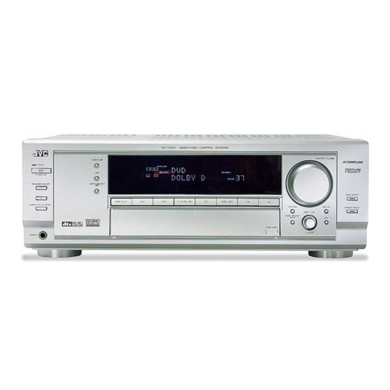
AUDIO/VIDEO CONTROL RECEIVER
RECEPTOR DE CONTROL DE AUDIO/VÍDEO
RECEPTOR DE COMANDO AUDIO/VÍDEO
RX-7032VSL
RX-7032V
SURROUND
STANDBY
STANDBY/ON
DSP
SPEAKERS ON/OFF
SURROUND/ DSP
1
OFF
2
DVD MULTI
DVD
VCR
SUBWOOFER OUT ON/OFF
PHONES
INSTRUÇÕES
AUDIO/VIDEO CONTROL RECEIVER
MASTER VOLUME
TV SOUND/DBS
CD
TAPE/CDR
FM
AM
SETTING
ADJUST
QUICK SPEAKER
SETUP
EXIT
PUSH OPEN
INSTRUCTIONS
MANUAL DE INSTRUCCIONES
RM-SRX7032U
REMOTE CONTROL
CATV/DBS
VCR
TV
AUDIO
DVD MULTI
DVD
CD
FM/AM
TV/DBS
VCR
TAPE/CDR
ANALOG/DIGITAL
INPUT
SURROUND
DSP
SURR/DSP
ANALOG
OFF
DIRECT
∗
∗
BASS BOOST
FRONT¥L
FRONT¥R
EX/ES
1
2
3
MENU
∗
∗
CD DISC
TEST
CENTER
SUB WOOFER
4
5
6
ENTER
∗
∗
MIDNIGHT
SURR¥L
SURR¥R
MODE
7/P
8
9
BASS BOOST
∗
∗
SOUND
DIGITAL EQ
SURR BACK
10/0
0
+10
RETURN
FM MODE
100+
CATV/DBS
CONTROL
+
+
+
ANALOG DIRECT
∗
CH/
LEVEL TV VOL
VOLUME
TV/VIDEO
−
−
−
VCR
TAPE/CDR
CONTROL
CONTROL
MUTING
/REW
FF/
REC PAUSE
DOWN
TUNING
UP
SLEEP
DIMMER
A/V CONTROL RECEIVER
For Customer Use:
Enter below the Model No. and Serial
No. which are located either on the rear,
bottom or side of the cabinet. Retain this
information for future reference.
Model No.
Serial No.
LVT1007-005A[US]
Advertisement
Table of Contents

Related Manuals for JVC 0303NHMMDWJEIN


![Receiver JVC LVT1007-010A[A] Instructions Manual](http://static.manualslib.com/public/img/no_image_60x60.svg)


Summary of Contents for JVC 0303NHMMDWJEIN
- Page 1 AUDIO/VIDEO CONTROL RECEIVER RECEPTOR DE CONTROL DE AUDIO/VÍDEO RECEPTOR DE COMANDO AUDIO/VÍDEO RX-7032VSL RX-7032V AUDIO/VIDEO CONTROL RECEIVER SURROUND STANDBY STANDBY/ON SPEAKERS ON/OFF SURROUND/ DSP DVD MULTI TV SOUND/DBS TAPE/CDR SUBWOOFER OUT ON/OFF PHONES INSTRUCTIONS MANUAL DE INSTRUCCIONES INSTRUÇÕES RM-SRX7032U REMOTE CONTROL CATV/DBS AUDIO DVD MULTI...
- Page 2 Warnings, Cautions and Others / Avisos, precauciones y otras notas / Advertêcias, precauções e outras notas / Caution –– STANDBY/ON switch! Disconnect the mains plug to shut the power off completely. The the mains line. The power can be remote controlled. Precaución ––...
- Page 3 Caution: Proper Ventilation To avoid risk of electric shock and fire and to protect from damage. Locate the apparatus as follows: Front: No obstructions open spacing. Sides: No obstructions in 10 cm from the sides. Top: No obstructions in 10 cm from the top. Back: No obstructions in 15 cm from the back.
- Page 4 Introduction We would like to thank you for purchasing one of our JVC products. Before operating this unit, read this manual carefully and thoroughly to obtain the best possible performance from your unit, and retain this manual for future reference.
-
Page 5: Table Of Contents
Activating the DVD MULTI Playback Mode ... 38 COMPU LINK Remote Control System ... 39 AV COMPU LINK Remote Control System ... 40 Operating JVC’s Audio/Video Components ... 42 Operating Audio Components ... 42 Operating Video Components ... 44 Operating Other Manufacturers’ Video Equipment ... -
Page 6: Parts Identification
Parts Identification Remote Control RM-SRX7032U REMOTE CONTROL CATV/DBS AUDIO DVD MULTI FM/AM TV/DBS TAPE/CDR ANALOG/DIGITAL INPUT SURROUND SURR/DSP ANALOG DIRECT EX/ES BASS BOOST MENU ∗ ∗ CD DISC TEST CENTER SUB WOOFER ENTER MIDNIGHT MODE ∗ ∗ SURR BACK SOUND DIGITAL EQ 10/0 100 +... -
Page 7: Display Window
SURROUND STANDBY STANDBY/ON SPEAKERS ON/OFF SURROUND/ DSP SUBWOOFER OUT ON/OFF PHONES EX / ES INPUT ANALOG Display Window INPUT ATT Front Panel STANDBY/ON button and STANDBY lamp (15) 2 • SPEAKERS ON/OFF 1 button (17) • SPEAKERS ON/OFF 2 button (17) 3 •... - Page 8 Display Window DUAL ANALOG DIGITAL AUTO SUBWFR Display Window 1 DUAL indicator (33) 2 ANALOG indicator (18) 3 DIGITAL AUTO indicator (18) 4 96/24 indicator (33) 5 MULTI indicator (38) 6 • PRO LOGIC indicator (32) • PRO LOGIC II indicator (33) 7 TUNED indicator (21) 8 STEREO indicator (21, 22) 9 NEO:6 indicator (33)
-
Page 9: Rear Panel
AUDIO DIGITAL IN VIDEO SUBWOOFER CENTER RIGHT LEFT FRONT SURR TV SOUND DIGITAL 1 (DVD) (REAR) RIGHT LEFT (REC) DIGITAL 2 (CD) (PLAY) DIGITAL 3 (TV) (REC) DIGITAL 4 (CDR) TAPE (PLAY) PCM/ DOLBY DIGITAL MONITOR / DTS DIGITAL OUT Rear Panel 1 DIGITAL IN terminals (14) •... -
Page 10: Getting Started
Getting Started This section explains how to connect audio/video components and speakers to the receiver, and how to connect the power supply. Before Installation General Precautions • Be sure your hands are dry. • Turn the power off to all components. •... -
Page 11: Connecting The Fm And Am Antennas
Connecting the FM and AM Antennas FM Antenna Connections IA L ANTENNA FM Antenna (supplied) Extend the supplied FM antenna horizontally. LOOP FM 75 Outdoor FM Antenna Cable COAXIAL (not supplied) A. Using the Supplied FM Antenna The FM antenna provided can be connected to the FM 75 Ω COAXIAL terminal as temporary measure. -
Page 12: Connecting The Speakers
Connecting the Speakers You can connect the following speakers: • Two pairs of front speakers to produce normal stereo sound. • One pair of surround speakers to enjoy the surround effect. • One surround back speaker or one pair of surround back speakers to enjoy to produce more effective surround effect. -
Page 13: Placing Speakers
Surround back speakers* Right / Left CAUTION : SPEAKER IMPEDANCE SINGLE USE See Instruction Manual For Connection – RIGHT LEFT RIGHT SURROUND BACK SPEAKERS SURROUND SPEAKERS Surround speakers * When using only one surround CAUTION : SPEAKER IMPEDANC back speaker, connect the ª cord to the RIGHT ª... -
Page 14: Connecting Audio/Video Components
Connecting Audio/Video Components When connecting individual components, refer also to the manuals supplied with them. Analog Connections If your audio components have digital audio output terminal, connecting them using the digital cords explained in “Digital Connections” (see page 14) will give you better sound quality. Audio component connections Use the cables with RCA pin plugs (not supplied). - Page 15 Video component connections Use the cables with RCA pin plugs (not supplied). Connect the white plug to the audio left jack, the red plug to the audio right jack, and the yellow plug to the video jack. • If your video components have S-video (Y/C-separation) and/or component video (Y, P ) terminals, connect them using an S- video cable (not supplied) and/or component video cable (not...
- Page 16 DVD player • When you connect a DVD player with stereo output jacks: To listen to the sound after connection, press DVD. COMPONENT VIDEO AUDIO VIDEO SUBWOOFER CENTER RIGHT LEFT FRONT SURR (REAR) DVD player Å To component video output ı...
-
Page 17: Digital Connections
Digital Connections This receiver is equipped with four DIGITAL IN terminals—one digital coaxial terminal and three digital optical terminals—and one DIGITAL OUT (optical) terminal on the rear. IMPORTANT: • When connecting a DVD player, digital TV broadcast tuner or DBS tuner using the digital terminals, you also need to connect it to the video jacks on the rear. -
Page 18: Basic Operations
Basic Operations The following operations are commonly used when you play any sound sources. Operations hereafter will be explained using the buttons on the front panel. You can also use the buttons on the remote control for the same functions if they have the same and similar names/marks. Daily Operational Procedure RX-7032V AUDIO/VIDEO CONTROL RECEIVER... -
Page 19: Adjusting The Volume
Speaker and signal indicators on the display By checking the following indicators, you can easily confirm which speakers you are activating and which signals are coming into this receiver. Speaker indicators Signal indicators SUBWFR What speaker indicators light depends on the speaker setting (for details, see “Setting the Speakers”... -
Page 20: Selecting The Front Speakers
Selecting the Front Speakers When you have connected two pairs of the front speakers, you can select which to use. RX-7032V AUDIO/VIDEO CONTROL RECEIVER To use the speakers connected to the FRONT SPEAKERS 1 terminals, press SPEAKERS ON/OFF 1 so that the SPEAKERS 1 indicator lights up on the display. -
Page 21: Setting The Dynamic Range
2. Press INPUT DIGITAL (or ANALOG/DIGITAL INPUT on the remote control) to select “DGTL AUTO.” The DIGITAL AUTO indicator lights up on the display. DIGITAL AUTO SUBWFR DIGITAL • When selecting “DGTL AUTO,” the following indicators indicate the digital signal format of the incoming signal. : Lights up when Linear PCM signals come LINEAR PCM : Lights up when Dolby Digital signals... -
Page 22: Turning Analog Direct On And Off
Turning Analog Direct On and Off You can enjoy the sound closer to the original source by overriding the sound adjustments such as speaker output level adjustments (see page 30), Digital Equalization (see page 30), Surround and DSP modes (see pages 32 to 37), Bass Boost (see page 20) and Midnight Mode (see page 18). -
Page 23: Reinforcing The Bass
The following basic operations are possible only using the remote control. BASS BOOST Reinforcing the Bass SOUND 10/0 MUTING Using the Sleep SLEEP Timer DIMMER Reinforcing the Bass You can boost the bass level. • Once you have made adjustment, it is memorized for each source. 1. -
Page 24: Receiving Radio Broadcasts
Receiving Radio Broadcasts You can browse through all the stations or use the preset function to go immediately to a particular station. Setting the AM Tuner Interval Spacing RX-7032V AUDIO/VIDEO CONTROL RECEIVER Some countries space AM stations 9 kHz apart, and other countries use 10 kHz spacing. -
Page 25: Selecting The Fm Reception Mode
3. Press FM/AM PRESET 5 or ∞ to select a channel number while the channel number position is flashing. ANALOG TUNED STEREO LINEAR PCM SUBWFR 4. Press MEMORY again while the selected channel number is flashing on the display. The selected channel number stops flashing. The station is assigned to the selected channel number. -
Page 26: Basic Settings
Basic Settings Some of the following settings are required after connecting and positioning your speakers while others will make operations easier. You can use QUICK SPEAKER SETUP to easily set up your speaker configuration. Setting the Speakers Configuration Quick Speaker Setup helps you to easily and quickly register the speaker size and speaker distance according to your listening room to create the best possible surround effect. -
Page 27: Basic Setting Items
Speakers (channels) number and size You can find how each of the speaker size is defined according to the number of connected speakers (speaker channel (CH) number) you select. In the following tables, “L” stands for “left front speaker,” “R” for “right front speaker,”... -
Page 28: Basic Procedure
Basic Procedure RX-7032V AUDIO/VIDEO CONTROL RECEIVER Before you start, remember... There is a time limit in doing the following steps. If the setting is canceled before you finish, start from step 1 again. Ex. When setting One Touch Operation to “ON.” 1. -
Page 29: Setting The Speaker Distance
7 Surround back speakers quantity—SBACK OUT Select the number of the surround back speakers connected. 1SPK: Select this to use 1 surround back speaker. 2SPK: Select this to use 2 surround back speakers. Note: If you have selected “NONE” for the surround back speakers (see page 25), this setting is not available. -
Page 30: Setting The Bass Sounds
Setting the Bass Sounds You can adjust subwoofer and bass sounds precisely according to your preference. 7 Subwoofer output—S WFR OUTPUT You can select the type of the signal which can be transmitted through the subwoofer. In other words, you can determine whether or not the bass elements of the front speaker channels are transmitted through the subwoofer regardless of the front speaker size setting (either “SMALL”... -
Page 31: Setting The Digital Input Terminals
Setting the Digital Input Terminals When you use the digital input terminals, register which components you have connected to the digital input terminals. 7 Digital coaxial terminal—DGTL IN COAX Set the component connected to the digital coaxial terminal (DIGITAL IN 1). DVD (initial setting), CD, TV (or DBS*) or CDR. -
Page 32: Adjusting Sound
Adjusting Sound You can make sound adjustment to your preference after completing basic setting. Basic Setting Items On the following pages, you can adjust the items listed below: • You can adjust only the items applicable to the current sound mode. -
Page 33: Adjusting The Equalization Patterns
Adjusting the Equalization Patterns You can adjust the equalization patterns to your preference. • Once you have made adjustment, it is memorized for each source. 7 Equalization adjustment—DIGITAL EQ You can adjust five frequency bands (center frequency: 63 Hz, 250 Hz, 1 kHz, 4 kHz, 16 kHz) within the range of –8 dB to +8 dB (“0 dB”... -
Page 34: Adjusting The Sound Parameters For The Surround And Dsp Modes
You can also use the remote control for adjusting the speaker output level. When using the remote control, you can make an adjustment while listening to test tone. 10/0 1. Press SOUND. The 10 keys are activated for sound adjustments. 2. -
Page 35: Using The Surround Modes
Using the Surround Modes This unit activates a variety of Surround modes automatically. The basic settings and adjustments stored (see pages 23 to 31) are applied. Reproducing Theater Ambience In a movie theater, many speakers are located on the walls to reproduce impressive multi-surround sounds, reaching you from all directions. - Page 36 Surround mode requires. • If the surround speakers and center speaker are set to “NONE” in the speaker setting, JVC’s original 3D-PHONIC processing (which has been developed to create the surround effect through the front speakers only) is used.
-
Page 37: Surround Modes Applicable To The Various Software
Surround Modes Applicable to the Various Software Available Surround modes vary depending on the speaker settings and the incoming signals. The table below shows the relation of the Surround modes and the incoming signals (with the surround back speakers and EX/ES setting). •... -
Page 38: Activating The Surround Modes
Activating the Surround Modes Available Surround modes vary depending on the speaker settings and the incoming signals. (See page 32.) Activating one of the Surround modes for a source automatically recalls the memorized settings and adjustments (see pages 23 to 31.) You can also use the buttons on the remote control for the same functions. -
Page 39: Using The Dsp Modes
When using the DAP mode, the sounds come out of all the connected and activated speakers. • If surround speakers are set to “NONE” in the speaker setting, JVC’s original 3D-PHONIC processing (which has been developed to create the surround effect through the front speakers only) is used. -
Page 40: Activating The Dsp Modes
ALL Channel Stereo mode This mode can reproduce a larger stereo sound field using all the connected (and activated) speakers. This mode cannot be used without activating the surround speakers. • If the front speakers are deactivated, “All Channel Stereo” cannot be selected. -
Page 41: Using The Dvd Multi Playback Mode
Using the DVD MULTI Playback Mode This receiver provides the DVD MULTI playback mode for reproducing the analog discrete output mode of the DVD player. Connection diagram COMPONENT VIDEO AUDIO VIDEO VIDEO SUBWOOFER CENTER RIGHT LEFT FRONT SURR (REAR) DVD player Å... -
Page 42: Compu Link Remote Control System
COMPU LINK Remote Control System The COMPU LINK remote control system allows you to operate JVC’s audio components through the remote sensor on the receiver. To use this remote control system, you need to connect JVC’s audio components through the COMPU LINK (SYNCHRO) jacks (see below) in addition to the connections using cables with RCA pin plugs (see page 10). -
Page 43: Av Compu Link Remote Control System
This receiver is equipped with the AV COMPU LINK-III, which adds a function to the previous version in order to operate JVC’s video components through the video components terminals. To use this remote control system, connect the video components you want to operate, following the diagrams below and the procedure on the next page. - Page 44 1. If you have already plugged your VCR , DVD player, TV and this receiver into the AC outlets, unplug their AC power cords first. 2. Connect your VCR, DVD player, TV and this receiver, using the cables with the monaural mini- plugs (not supplied).
-
Page 45: Operating Jvc's Audio/Video Components
Operating JVC’s Audio/Video Components You can operate JVC’s audio and video components with this receiver’s remote control, since control signals for JVC’s components are preset in the remote control. Operating Audio Components IMPORTANT: To operate JVC’s audio components using the supplied remote control: •... - Page 46 CD changer After pressing CD DISC, you can perform the following operations on a CD changer: Start playing. Return to the beginning of the current (or previous) track. ¢: Skip to the beginning of the next track. Stop playing or recording. Pause playing.
-
Page 47: Operating Video Components
COMPU LINK jacks (see page 39) in addition to the connections using cables with RCA pin plugs (see pages 11 and 12). • Some JVC’s VCRs can accept two types of the control signals— remote code “A” and “B.” Before using this remote control, make sure that the remote control code of the target VCR is set to code “A.”... -
Page 48: Operating Other Manufacturers' Video Equipment
Operating Other Manufacturers’ Video Equipment This remote control supplied with the receiver can transmit control signals for other manufacturers’ TVs, CATV converters, DBS tuners, VCRs and DVD players. When operating the other manufacturers’ components, refer also to the manuals supplied with them. •... - Page 49 To change the transmittable signals for operating a CATV converter or DBS tuner 1. Press and hold CATV/DBS 2. Press CATV/DBS CONTROL. 3 Enter a manufacturer’s code using buttons 1 – 9, and 0. See the list on the right column to find the code. 4.
- Page 50 To change the transmittable signals for operating another manufacturer’s VCR 1. Press and hold VCR 2. Press VCR. 3. Enter manufacturer’s code using buttons 1–9, and 0. See the list on the right column to find the code. 4. Release VCR The following buttons can be used for operating a VCR: Turn on and off a VCR.
- Page 51 To change the transmittable signals for operating another manufacturer’s DVD player 1. Press and hold AUDIO 2 Press DVD. 3. Enter a manufacturer’s code using buttons 1–9, and 0. See the list on the right column to find the code. 4.
-
Page 52: Troubleshooting
Troubleshooting Use this chart to help you solve daily operational problems. If there is any problem you cannot solve, contact your JVC’s service center. PROBLEM The display does not light up. No sound from speakers. Sound from one speaker only. -
Page 53: Specifications
Specifications Amplifier Output Power At Stereo operation per channel, min. RMS, driven into 8 Ω, Front ch: 100 W 1 kHz, with no more than 0.8% total harmonic distortion. (IEC268-3/DIN) At Surround operation: per channel, min. RMS, driven into 8 Ω at Front ch: 100 W 1 kHz, with no more than 0.8% total harmonic... - Page 54 Caso não corresponda, reajuste o selector de voltagem a fim de evitar avarias ou riscos de incêndio e choque eléctrico. VICTOR COMPANY OF JAPAN, LIMITED 110V 220V 127V 230 - 240V VOLTAGE SELECTOR 0303NHMMDWJEIN...
Need help?
Do you have a question about the 0303NHMMDWJEIN and is the answer not in the manual?
Questions and answers