
Related Manuals for Invacare LiNX


Summary of Contents for Invacare LiNX
- Page 1 Invacare® LiNX en Controls System Service Manual DEALER: Keep this manual. The procedures in this manual MUST be performed by a qualified technician.
- Page 2 All rights reserved. Republication, duplication or modification in whole or in part is prohibited without prior written permission from Invacare. Trademarks are identified by ™ and ®. All trademarks are owned by or licensed to Invacare Corporation or its subsidiaries unless otherwise noted.
-
Page 3: Table Of Contents
9.6 Setting up a system for latched driving ....81 4.1 The LiNX Access Key ......40 9.7 Adjust quadrant operation. -
Page 4: General
• Spare parts MUST match original Invacare parts. Only order to ensure safety when handling the product, read the use spare parts which have been approved by Invacare. manual carefully and follow the safety instructions. • We reserve the right to make any alterations on the grounds of technical improvements. -
Page 5: Safety
Safety To maximize performance, minimize EMC emissions, 2 Safety maximize EMC and ESD immunity, and to keep the cabling of the wheelchair safe and tidy, observe the following guidelines: 2.1 Safety information • All wiring should comply with the requirements of WARNING! ISO7176-14. -
Page 6: Assembly
Invacare® LiNX 3 Assembly IMPERIAL METRIC inch 3.1 Tightening torques 7.5406 19/64 7.9375 5/16 CAUTION! Risk of damage to mobility device due to 8.3344 21/64 improperly tightened screws, nuts or plastic 8.7313 11/32 connections. – Always tighten screws, nuts etc. to the stated 9.1281... -
Page 7: Overview Components
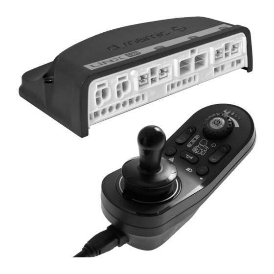
Assembly 3.3 Overview components Remote modules DLX-REM400 Remote modules • Touch screen interface to facilitate: – Multiple drive functions – Multiple powered DLX-REM110 seating functions • Drive function Two or more actuators – Lighting function • Multipurpose buttons • 3.5 mm jack sockets DLX-REM500 •... - Page 8 Invacare® LiNX ASL components ASL components ASL 138 ASL 106 Extremity Control Joystick Four Switch Proximity Array ASL 504 Remote Stop Switch Wireless Accessories for ATOM: ASL 133 • Wireless Mouse Compact Single Switch Emulator ASL 558 Joystick • Wireless Triple Switch...
- Page 9 Assembly Power modules LiNX seating modules and interfaces DLX-PM75AL DLX-IN500 Input module • 78 A maximum current • 2 x bus sockets • DB9 connector for • Dynamic Load proportional and Compensation switched inputs • Adaptive Load • 12 V (200 mA) power...
-
Page 10: Power Module Mounting
The mounting orientation of the power module that is When placing the power modules at an angle, ensure that specified by Invacare per wheelchair model must be kept. the connectors B facing downwards, so that the connector recesses will not collect or retain foreign matter or liquids. -
Page 11: Mounting Positions On Wheelchairs
Assembly Testing A Rear B Connectors The LiNX system must be fully tested after all modules and cables have been installed. C Top D Base 3.5 Mounting positions on wheelchairs The positions of the power modules A and DLX-ACT200/400 B depending on wheelchair model and —configuration are shown in the table below. -
Page 12: Port Configurations (Factory Set-Up)
3.7 Port configurations (Factory set-up) DLX-PM75AL, DLX-PM120AL Actuator ports, properties and behavior per actuator are defined by Invacare. You can change speed, direction and operation mode. This is done in different menus, refer to 7.5 Modifying seating parameters, page 62. -
Page 13: Port Configuration For Non-Expandable Systems (Us Version)
Assembly Port configuration without lifter Power module DLX-ACT200 DLX-ACT400 Port configuration with lifer Power module DLX-ACT200 DLX-ACT400 3.7.2 Port configuration for non-expandable systems (US version) Non-expandable systems are fitted with external switches and a functionkey, to control the powered seating functions. For more information about functionkeys, refer to chapter 3.7.4 Port configurations for functionkeys, page 15. -
Page 14: Port Configuration For Systems With Dlx-Rem400 And Dlx-Rem500 (With Ultra Low Maxx Seat)
Invacare® LiNX Channel Seating motion (Icon) Seating function (Operation) Recline only Proportional FWD/REV Tilt only Proportional FWD/REV LNX only Proportional FWD/REV Two actuator systems Seating motion Seating motion Seating motion Seating motion Seating motion Seating Channel (Icon) (Icon) (Icon) (Icon) -
Page 15: Port Configurations For Functionkeys
Assembly Channel Seating motion (Icon) Seating function (Operation) Legrest right Proportional FWD/REV Legrest left Proportional FWD/REV Proportional FWD/REV Recline Proportional FWD/REV 3.7.4 Port configurations for functionkeys If the system is fitted with an external switch, to control the powered seating functions (except a 10 way switch), a functionkey is required to interface the switches. -
Page 16: Wiring Diagrams
Invacare® LiNX Independent of type FKEY02 or FKEY02TDC the 4–way button switch or the 4–way toggle switch must be plugged into the DB9 socket. 3.8 Wiring diagrams The following diagrams show the wiring for a wheelchair in a complex configuration including multiple actuators, lights and attendant control unit. - Page 17 Assembly Model A A A B B B C C C D D D E E E F F F G G G H H H Kite • 2500 • 1500 • • • • 1500 • 1700 • Spectra •...
- Page 18 Invacare® LiNX Cable length may vary depending on mounting positions of primary and secondary remotes and of 4–way connector GLM-CONX4. Model C C C A A A B B B D D D E E E F F F Kite •...
- Page 19 Assembly Cable length may vary depending on mounting positions of primary and secondary remotes. Model A A A B B B Kite • 1500 mm • 1500 mm • 1500 mm • 1500 mm Spectra XTR HD, Bora/Spectra XTR Standard TDX SP2 •...
- Page 20 Invacare® LiNX Wiring for Fox with Modulite Drive only with ACU Cable length may vary depending on mounting positions of primary and secondary remotes and of 4–way connector GLM-CONX4. • 1000 mm • 1200 mm • 1000 mm 1605129-C...
- Page 21 Assembly Wiring for Fox with Modulite Recline only Cable length may vary depending on mounting positions of primary remote. • 1000 mm • 1000 mm 1605129-C...
- Page 22 Invacare® LiNX Wiring for Fox with Modulite Recline only and ACU Cable length may vary depending on mounting positions of primary and secondary remotes and of 4–way connector GLM-CONX4. • 1000 mm • 300 mm • 1200 mm • 1000 mm...
- Page 23 Assembly Wiring for Non expandable systems with Ultra Low Maxx seat (US only) Cable length may vary depending on mounting positions of primary and secondary remotes and of 4–way connector GLM-CONX4. Configura- A A A B B B C C C D D D E E E F F F...
- Page 24 Invacare® LiNX Configura- A A A B B B C C C D D D E E E F F F G G G H H H tion KEY02 • LNX only • 1200 • • 1200 • • 1500 •...
- Page 25 Assembly Wiring for configurations with Ultra Low Maxx seat Cable length may vary depending on mounting positions of primary and secondary remotes and of 4–way connector GLM-CONX4. Depending on configuration, the Egg switch ASL300 can be connected to the primary remote. 1605129-C...
-
Page 26: Mounting The Primary Remotes
Invacare® LiNX Configuration w tilt, w recline, w w tilt, w recline, w/o w tilt, w/o recline, w tilt, w/o recline, w lifter lifter w/o lifter lifter • 1200 mm • 1200 mm • 1500 mm • 1500 mm •... -
Page 27: Mounting Dlx-Rem2Xx For Ultra Low Maxx
Assembly 3. Pull screws F through washers E, bracket C and 1. Pull screws A through washers B, mounting plate C bracket G and tighten screws. and bottom side of bracket D. 2. Tighten bottom side of the bracket to push bar with the top side of the bracket E and nuts F. - Page 28 Invacare® LiNX 1. Mount LiNX remote adapter B with screws A to remote The LiNX remote adapter can be turned 90° right or left for more adjustment options. 2. Mount remote to Quad Link F with screw D, Nord-Lock washer E and serrated lock washer G.
-
Page 29: Mounting The Dlx-Rem400
Assembly Swing away remote holder • 4 mm Allen key • 3 mm Allen key • 8 mm wrench • 10 mm wrench Attach clamp C to bracket I with screws K and washers J. 1. Pull screws D through bracket C, remote holder and washers B. -
Page 30: Mounting The Dlx-Rem500
Invacare® LiNX 1. Mount LiNX remote adapter B with screws A to remote Mount remote A with support B and support drum C The LiNX remote adapter can be turned 90° right to clamp D with screws F and washers E. -
Page 31: Mounting The Secondary Remotes
Assembly 3.10 Mounting the secondary remotes For more information about how remote holders are mounted to the wheelchair, refer to the service manual of the seating system. 3.10.1 Mounting the DLX-ACU200 Mounting for Modulite seating system • 3 mm Allen key •... -
Page 32: Mounting The Dlx-Cr400
Invacare® LiNX Set remote A in clamp B and tighten screw D and nut Mounting for Ultra Low Maxx seating system • 3 mm Allen key • 5 mm Allen key • 8 mm wrench Mount joystick holder A to DLX-CR400 adapter B with screws C, washers D and nuts E. -
Page 33: Mounting The Dlx-Rem050
Assembly Mounting positions Risk of damage to the remote The maximum torque to tighten the screw is 1 Nm. – Do not exceed this rating as it may damage the remote. Set remote D in clamp A and tighten screw B and washer C with nut E. - Page 34 Invacare® LiNX Insert remote O into tray A. 6. Fix adapter block K to angle bracket F with screw H Insert joystick O in clamp N, pull clamp over adapter and washer I. block K and fix with screws L.
-
Page 35: Mounting The Micro Extremity Control Joystick
Assembly 3. Fix clamp plate B, clamp ball C and upper clamp plate 3.11.2 Mounting the Micro Extremity Control Joystick D with screws E. Lateral tray mount • 1/8” Allen key • 5/32” Allen key • 3/16” Allen key Mount angle bracket H with screws I to tray A. 1. -
Page 36: Mounting The Pediatric Compact Joystick
Invacare® LiNX 1. Insert clamp plate B into cutout on tray A. 2. Fix clamp plate B, clamp ball C and upper clamp plate D with screws E. Insert remote O into clamp N. Pull clamp over adapter Insert remote J from below into tray A. Make sure, block K and tighten with screws L. - Page 37 Assembly Mount angle bracket H with screws I to tray A. Fix adapter block K to angle bracket F with screw H and washer I. Nucleus tray mount • 1/8” Allen key • 5/32” Allen key • 3/16” Allen key Fix adapter block M to angle bracket H with screw J and washer K.
-
Page 38: Mounting The Eclipse Tray With Proximity
Invacare® LiNX 3.11.4 Mounting the eclipse tray with proximity sensors Orientation wrong Orientation right • 3/32” Allen key • 5/32” Allen key • 3/16” Allen key • 4x loop straps 25x100 mm • 4x hook straps 25x100 mm 3.12.1 Mounting the 10 way switch for Modulite Mounting at the front •... -
Page 39: Mounting The 10 Way Switch For Ultra Low
Assembly For the possible positions of the attendant control unit, refer to 3.9.3 Mounting the DLX-REM400, page 3.12.2 Mounting the 10 way switch for Ultra Low Maxx Mounting at the front In combination with DLX-REM2XX or DLX-REM400 • 3 mm Allen key •... -
Page 40: Overview Linx Access Tools
Windows 7 or later. and REM500 the same way. The programming and diagnostic tools communicate with a The LiNX Access Key has a blue status indicator to show LiNX system via Bluetooth. The Bluetooth capability of a when it is: LiNX system is provided by a LiNX Access Key inserted into the remote module’s XLR socket. -
Page 41: Overview Functions
Overview LiNX Access tools 4.2 Overview Functions Top level parameter categories Parameter subcategories Chair Configs Restore to Default Config Diagnostics/Chair Log For details see following table Speed Demand Turn Demand Motor Voltage Live Diagnostics Motor Current Motor Resistance Battery Voltage... -
Page 42: Overview User Preferences
Invacare® LiNX Top level parameter Parameter subcategories User Input Input Module Control Inputs/Outputs Jack Socket Angle Sensor - Triggers ACT200 Control Inputs/Outputs 1–4 Angle Sensor - Triggers ACT400 Control Inputs/Outputs 1–4 Identification Actuator Motions Seating Motion Behavior Actuator Channels Optional 4.2.1 Overview User Preferences... - Page 43 A restricted user is an occupant or attendant that is prevented from being user-in-charge once a system is powered up. By default, there are no restricted users in a LiNX system and both the attendant and the occupant can request to be user-in-charge at any time by pressing power button. However, for safety and other reasons, it may...
- Page 44 Invacare® LiNX be appropriate to restrict the attendant or occupant from becoming user-in-charge after power-up. If restricted, any request to be user-in-charge is denied. To restrict a user, set this parameter to: • No Restriction: Default • Occupant Priority: to restrict attendant.
-
Page 45: Suggested Programming Procedure
LiNX system off. The following outlines a suggested programming procedure for setting up the LiNX system. It is not prescriptive and should be used as a guideline only. The following chapters show the preferred order in which... -
Page 46: Calibrating Adaptive Load Compensation
Adaptive Load Compensation (ALC). more sluggish than anticipated. Invacare recommends adding the motor resistance Load Compensation Percentage is only applied when values automatically, using Adaptive Load Adaptive Load Comp Enabled is set to on. -
Page 47: Step 4 - Adjust Speed Settings
Suggested programming procedure Click on Connection menu. Drive chair until both left and right motor compensation Select Run ALC Calibration. processes have been completed. Click on Done. Click on Recalibrate. 5.4 Step 4 – Adjust speed settings The following parameters must be set for each drive function. Click on Start. -
Page 48: Step 5 - Adjust Acceleration Settings
Invacare® LiNX Adjust turn speed Set speed dial or slider to maximum and deflect joystick either left or right to turn wheelchair on spot. Wait until wheelchair reaches a steady turning speed. Adjust Max Turn Speed parameter until turn speed seems like a comfortable maximum. - Page 49 Suggested programming procedure speed. Adjust Forward Acceleration parameter if wheelchair gets up to steady speed too quickly or slowly. Repeat until acceleration feels comfortable and safe. Adjust forward deceleration To set deceleration rate in forward direction, release joystick once wheelchair has reached steady forward speed. Adjust Forward Deceleration parameter if wheelchair slows down too quickly or slowly.
-
Page 50: Using The Linx Access Ios Tool
6.1.2 Changing the program name To work on a connected wheelchair, select Connection context. If you are not connected to a LiNX system the Connect to device screen is displayed. Otherwise, the last screen that you were working with, is displayed. - Page 51 The program name in the picture is for a Center Wheel drive F = DLX-PM75LA TDX SP2 with a DLX-REM120LA, 8 km/h, Seat lifter with powered tilt and CoG shift, Standard LiNX and LED light. The G = DLX-PM120 revision of the program name is 00.
-
Page 52: Home Screen
The Connect to device screen is displayed when you are in Connection context before connecting to a LiNX system. From this screen you can search for and connect to a LiNX Access Key (LAK). Connecting the LiNX Access iOS tool with a wheelchair 1. -
Page 53: Modifying A Program
2. Select Write to Chair. the process of setting up or testing various applications and scenarios. After writing to the wheelchair, the LiNX Access tool cycles the system’s power and automatically reconnects to the system. The Application menu dialogue in this picture shows all available options, when you are in Connection context. -
Page 54: Saving Programs
6.3.6 Saving programs Using Save 1. Click on Application menu button. 2. Select Save As. After saving the program, the LiNX Access tool displays a message with the file’s name and that saving was successful. 1. Click on Application menu button. -
Page 55: Storing The Lak Certificate
(.lci files) when in the File context mode. The Access Level Certificate is taken from a connected LiNX Access Key and provides the levels to your stored files. To edit your files with a distributor’s access level, you will need to store an Access Level Certificate from a distributor-level LiNX Access Key. -
Page 56: Opening Files
Invacare® LiNX 6.4.2 Opening files 3. Click on trash can icon at the bottom of the screen. 4. Click on Done to finish. 6.4.4 E-mailing files Select Edit from Load From File screen. 2. Select one or more files from file list. - Page 57 Using the LiNX Access iOS tool If you choose your mail client, selected program files are added as attachments to e-mail. Complete e-mail and click on Send. 6. Click on Done to finish. The iOS Share Sheet opens up. Select desired option.
-
Page 58: Modifying Wheelchair Configuration With Ios Tool
Invacare® LiNX Delete function of profile 7 Modifying wheelchair configuration with iOS tool A profile cannot be deleted until its functions are deleted. 7.1 Profile and function actions 1. Select function or profile you want to delete. In bulk edit mode: •... - Page 59 Modifying wheelchair configuration with iOS tool Copy function 1. Tap on function you want to copy. Select User Input. Tap Done. 4. Tap Done to return to Home screen. Tap on Duplicate. Copied function appears directly under original function. For more information about modifying the drive parameters, 3.
-
Page 60: Modifying Function And Profile Names
Invacare® LiNX Add profile 1. Tap on icon C. Tap Duplicate or Delete. Enter profile name. Select User Input. 2. Add function to profile. 3. Tap Done to return to Home screen. User Navigation Error is displayed as long as no function is added to the new profile. -
Page 61: Modifying Drive Parameters Graphically
Modifying wheelchair configuration with iOS tool 1. Open Drive or Seating function. Tap on field with Editing speed settings function name. The Speed graph allows you to adjust: • Maximum Forward Speed A • Maximum Turn Speed B Unlock Bulk Mode before modifying the name. •... -
Page 62: Modifying Drive Parameters Numerically
Invacare® LiNX 7.5 Modifying seating parameters • Press and hold the Max Forward Speed circle to be taken to the Forward acceleration A / deceleration B Seating motion screen. • Press and hold the Max Turn Speed circle to be taken to the Turn acceleration C / deceleration D screen. - Page 63 Modifying wheelchair configuration with iOS tool • Left/Right: Moving joystick left or right to Switch-type Proportional type control motion. • Four Quadrant: Using all four joystick quadrants to control motions. Switched Latched Proportional Toggle Toggle / latch Choose one of the switch-type modes to operate the motion at a fixed speed.
-
Page 64: Joystick Switch Threshold
Invacare® LiNX 7.6 Joystick Switch Threshold Operation Purpose Toggle Activates the motion in Sets the percentage of joystick movement required to one direction (extend activate an output when the joystick is operating as a or retract) for the switched input device. -
Page 65: Adjust Quadrant Operation
Modifying wheelchair configuration with iOS tool 7.7 Adjust quadrant operation If required, each quadrant can be reassigned with a different direction. Note that the Reverse Quadrant Operation This parameter sets the drive function’s user input to operate parameter is not applicable in 3Q - Reverse Only mode. in 3–quadrant (3Q)or 4–quadrant (4Q) mode. -
Page 66: Enable Indirect Navigation
Invacare® LiNX • Left 4. Set Navigation Timeout to Yes. • Right 5. From Home screen open User Preferences. • Ignored If Ignored is selected, the wheelchair does not move in any direction when the input’s reverse quadrant is selected. -
Page 67: Installing / Setting Up Alternative Inputs
Modifying wheelchair configuration with iOS tool 7.9 Installing / Setting up alternative inputs 3. From Home screen open Chair Setup –> Modules –> IN 5xx or TPI, depending on component input. There are different types of alternative inputs, that interface differently to the system. -
Page 68: Sip And Puff Calibration
Invacare® LiNX 1. Add user function for Sip and Puff module. For more 7.10.1 Sip and Puff calibration information about adding profiles and functions, refer to Primary input operations, such as driving, are 7.1 Profile and function actions, page 58. - Page 69 Modifying wheelchair configuration with iOS tool 4. If Sip tab is open, user performs hard sip and soft sip in no specific order. If Puff tap is open, user performs hard puffs and soft puffs in no specific order. For each sip and puff, a pressure level B is recorded on calibration tool.
- Page 70 Invacare® LiNX or puff. Pressure inputs F that fall away into neutral zone ramp time C needs to be extended, so the pressure input before ramp time expires are not registered as an input. J is registered as a hard sip or puff.
-
Page 71: Using The Linx Access Pc Tool
Click on Browse button and select different folder. 2. Click Next to continue. Step 5 Select I accept option. By default, a desktop icon will be added for the LiNX access 2. Click Next button. PC tool and the wheelchair program files (*.lci) will be Step 3 associated with the LiNX Access PC tool. -
Page 72: Using Bluetooth On A Computer
8.1.1 Using Bluetooth on a computer You need a Bluetooth connection to communicate between the LiNX Access PC tool and a LiNX system. You can use a computer’s built-in Bluetooth adaptor (usually found on laptops) or an external USB Bluetooth adaptor. -
Page 73: Concepts
Click on Yes button to continue. To manually check for updates, you can either: • check the Dynamic Controls website at www.dynamiccontrols.com or • from the main menu on the LiNX Access PC tool, click on Help and then on Check for updates. 1605129-C... -
Page 74: Connection Context Actions
Find more button (top left) to force application to search for more LiNX Access Keys, or c. if list is too long to read, enter LiNX Access Key into Filter connections text box to locate LiNX Access Key in list. -
Page 75: Save A Program As A File
3. Select Load as Current. 4. A message is displayed warning you, that current If you do not store you LAK certificate from your LiNX Access configuration will be overwritten. Key, you have read-only access to your stored files and Click either on Discard to finish or Cancel if you do not therefore you are not able to edit them. -
Page 76: File Context Actions
2. Select Open file to open the Open file dialogue. 3. Select file. After selecting a file, the LiNX Access PC tool opens the file under its own tab. The tab is named with the file name. Close a file Select desired bundle file and click Open. -
Page 77: Modifying Wheelchair Configuration With Pc Tool
Modifying wheelchair configuration with PC tool Add user function 9 Modifying wheelchair configuration with PC tool Click on icon B. 9.1 Profile and function actions In bulk edit mode: • profiles can be added and deleted, • functions can be added, deleted, copied and moved. A system always includes a REM2xx Drive Function profile and a REM2xx Seating Function profile. -
Page 78: Modifying Function And Profile Names
Invacare® LiNX 9.3 Modifying drive parameters 1. Select a parameter to edit. 2. Click on the parameter’s name to open the parameter’s details. Default, minimum and maximum values will be displayed, as well as the parameter’s summary. 3. There are different ways to modify the parameters: a. - Page 79 Modifying wheelchair configuration with PC tool Changing motion name • Left/Right: Moving joystick left or right to control motion. • Four Quadrant: Using all four joystick quadrants to control motions. Click on Motion Name. 2. Enter new motion name. If Four Quadrant is selected, all quadrant parameters Seating function can be edited individually.
-
Page 80: Joystick Switch Threshold
Invacare® LiNX Choose one of the switch-type modes to operate the Operation Purpose motion at a fixed speed. The motion is activated Activates and latches the Toggle / latched when the joystick is deflected past the Joystick Switch motion in one direction... -
Page 81: Setting Up A System For Latched Driving
Connect the external stop switch to a control input. Invacare recommends to connect the external stop switch to the input module. -
Page 82: Adjust Quadrant Operation
Invacare® LiNX 1. Open Chair Setup –> Modules –> desired input to which 1. Open Functions –> open desired drive function. external stop switch is connected. Set type of latched driving with Latch Driving. For more information about types of latched driving, refer to user Set Input Type to desired input, for example, manual of remote. -
Page 83: Adjust Drive Directions
Modifying wheelchair configuration with PC tool 3Q - Automatic Toggle When 3Q - Automatic Toggle is selected, the user input can drive the wheelchair forward, reverse, left and right. The forward and reverse directions are controlled by the user toggling the forward quadrant. If required, each quadrant input can be reassigned with a different direction. -
Page 84: Enable Indirect Navigation
Invacare® LiNX • Ignored If Ignored is selected, the wheelchair does not move in any direction when the input’s left quadrant is selected. Right Quadrant Operation This parameter sets the direction that the wheelchair moves when the right quadrant of the user input is selected. -
Page 85: Programming External Switches
Modifying wheelchair configuration with PC tool Other parameters The options are: • Not Connected • 10–way switch • 17–way switch • Momentary button • Short + Long Press button A Timeout for navigation entry: Sets inactivity time required before system enters navigation mode, for navigation mode with Navigation Timeout only. -
Page 86: Programming Multipurpose Buttons
Invacare® LiNX The options are: Other parameters • Extend • Retract • Latched Extend • Latched Retract • Toggle • Latched Toggle A Enable Input Type: When set, Input Type is enabled. B Fail-safe mode: When turned on, external switch must not be removed from input, otherwise wheelchair does not drive. -
Page 87: Installing / Setting Up Alternative Inputs
Modifying wheelchair configuration with PC tool Component Input Sip and Puff Input Module IN5xx Sip and Puff Head Array Input Module IN5xx Pediatric Compact Joystick Input Module IN5xx Head Array Chin control Compact Single Switch Joystick Four Switch Proximity Array Remote Stop Switch Power Module To install a Remote Stop Switch, just connect to the... -
Page 88: Sip And Puff Installation
Invacare® LiNX Set User Input Configuration to desired component. Set Function User Input to Input Module. Options are: Same procedure for drive, seating and connectivity functions. • Proportional Joystick: Pediatric Compact Joystick, 4. Open Chair Setup –> Modules –> IN 5xx. - Page 89 Modifying wheelchair configuration with PC tool • Minimum limit for soft puff, 4. User performs hard puff, soft puff, hard sip and soft sip • minimum limit for hard puff, in no specific order. For each sip and puff, a pressure •...
- Page 90 Invacare® LiNX When setting Sip and Puff Ramp Time, consideration should be given to users, who cannot produce a hard sip or puff within the ramp time. If ramp time is set too low, a user may not be able to reach the hard zone G in time and a soft sip or puff is registered instead of the intended hard sip or puff.
-
Page 91: Diagnostics
Module software version • Module serial number • Access Level of LiNX Access Key Click on Back or Close button, to exit the System Summary. Reading battery usage To view more information about a battery statistic, click on a statistic and a helpful description is displayed in the local help panel. - Page 92 The total time the LiNX system is operated with the state of charge between 0 and 20%. Band 2 Indicator Time The total time the LiNX system is operated with a state of charge between 20 and 40%. Band 3 Indicator Time...
-
Page 93: Viewing Real-Time Diagnostics
10.4 Viewing real-time diagnostics Drive statistic Details Time Near Maximum The duration the current The real-time diagnostics are only available when the LiNX Current was within 20% of maximum Access iOS tool is connected to a wheelchair. threshold. Click on the Real Time Diagnostics button to view the... - Page 94 Notes...
- Page 95 Notes...
- Page 96 Notes...
- Page 97 Notes...
- Page 98 Invacare Sales Companies Australia: Canada: Ireland: New Zealand: Invacare Australia PTY. Ltd. Invacare Canada LP Invacare Ireland Ltd, Invacare New Zealand Ltd 1 Lenton Place, North Rocks NSW 570 Matheson Blvd E. Unit 8 Unit 5 Seatown Business Campus 4 Westfield Place, Mt Wellington 1060...
Need help?
Do you have a question about the LiNX and is the answer not in the manual?
Questions and answers