
Related Manuals for Invacare LiNX


Summary of Contents for Invacare LiNX
- Page 1 Invacare® LiNX en Controls System Service Manual PROVIDER: Keep this manual. The procedures in this manual MUST be performed by a qualified technician.
- Page 2 All rights reserved. Republication, duplication or modification in whole or in part is prohibited without prior written permission from Invacare. Trademarks are identified by ™ and ®. All trademarks are owned by or licensed to Invacare Corporation or its subsidiaries unless otherwise noted.
-
Page 3: Table Of Contents
9.5.6 Upgrading Firmware......117 5.1 The LiNX Access Key ......57 9.5.7 Restoring Default Wheelchair Configurations . - Page 4 Invacare® LiNX 10 Modifying wheelchair configuration with PC tool ..121 10.1 Profile and Function Actions .....121 10.2 Modifying function and profile names .
-
Page 5: General
It is therefore covered by the power wheelchair’s CE accessory. Additional manuals can be ordered from marking. See the power wheelchair’s documentation for Invacare. See addresses at the end of this document. more information. You can find information about ordering spare parts in Invacare reserves the right to alter product specifications the spare parts catalogue. -
Page 6: Safety
Invacare® LiNX To maximize performance, minimize EMC emissions, 2 Safety maximize EMC and ESD immunity, and to keep the cabling of the wheelchair safe and tidy, observe the following guidelines: 2.1 Safety information • All wiring should comply with the requirements of WARNING! ISO7176-14. -
Page 7: Assembly
Assembly 3 Assembly IMPERIAL METRIC inch 7.5406 19/64 3.1 Tightening Torques 7.9375 5/16 CAUTION! 8.3344 21/64 Risk of damage to mobility device due to improperly tightened screws, nuts or plastic 8.7313 11/32 connections. 9.1281 23/64 – Always tighten screws, nuts etc. to the stated tightening torque. -
Page 8: Overview Components
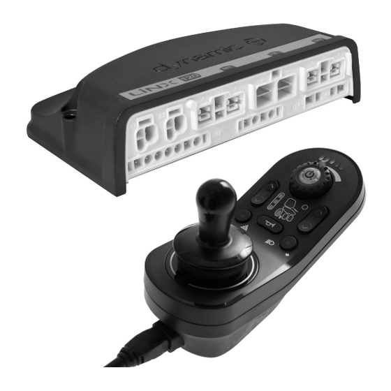
Invacare® LiNX 3.3 Overview Components Secondary remote modules LiNX IDC Remote modules Intuitive Dual Control • On/Off button • Speed dial • Display for drive direction indicator DLX-REM110 • Drive function DLX-CR400 Compact Remote • On/Off button • Menu button •... - Page 9 Assembly ASL components ASL components ASL 138 ASL 104/ASL 104P Extremity Control Joystick Head Array ASL 106 Four Switch Proximity Array ASL 133 Compact Single Switch Joystick ASL 504 Remote Stop Switch Wireless Accessories for ATOM: • Wireless Mouse Emulator ASL 558 •...
- Page 10 Invacare® LiNX Power modules LiNX seating modules and interfaces DLX-PM75AL DLX-IN200 Input module • 78 A maximum current • 2 x bus sockets • DB9 connector for • Dynamic Load proportional and Compensation switched inputs • Adaptive Load • 12 V (200 mA) power...
-
Page 11: Power Module Mounting
Assembly 3.4 Power module mounting Powered seating accessories The mounting orientation of the power module that is 4–way button switch specified by Invacare per wheelchair model must be kept. • 4 switches Dimensions of the power modules • DB9 connector DLX-PM60, DLX-PM75, DLX-PM120 4–way toggle switch... -
Page 12: Mounting Positions On Wheelchairs
Incorrect mounting D Base Testing The LiNX system must be fully tested after all modules and cables have been installed. 3.5 Mounting positions on wheelchairs The positions of the power modules A and DLX-ACT200/400 B depending on wheelchair model and —configuration are shown in the table below. -
Page 13: Port Pin-Outs
B Motor / park brake port M1 C Battery port Actuator ports, properties and behavior per actuator are defined by Invacare. You can change speed, direction and D Motor / park brake port M2 operation mode. This is done in different menus, refer to E Utility port 8.7 Modifying Seating Parameters, page 90. -
Page 14: Port Configurations For Systems With Dlx-Rem2Xx (Eu-Version With Modulite Seat)
Invacare® LiNX The “AL” power modules that feature actuators and the configuration. The following chapters detail the port lights, have two actuator ports. If required, the system is set-up per module/configuration. completed with the DLX-ACT200 or DLX-ACT400, based on 3.7.1 Port configurations for systems with DLX-REM2xx (EU-Version with Modulite seat) -
Page 15: Port Configuration For Non-Expandable Systems (Us Version)
Assembly Port configuration with lifer Power module DLX-ACT200 DLX-ACT400 3.7.2 Port configuration for non-expandable systems (US version) Non-expandable systems are fitted with external switches and a functionkey, to control the powered seating functions. For more information about functionkeys, refer to chapter 3.7.4 Port Configurations for Functionkeys, page 17. Single actuator systems Channel Seating motion (Icon) -
Page 16: Port Configuration For Systems With Dlx-Rem400 And Dlx-Rem500 (With Ultra Low Maxx Seat)
Invacare® LiNX Two actuator systems Seating motion Seating motion Seating motion Seating motion Seating motion Seating Channel (Icon) (Icon) (Icon) (Icon) (Icon) function (Operation) Tilt Tilt Recline Left leg Recline Proportional FWD/REV Lifter Right leg Tilt Proportional FWD/REV 3.7.3 Port configuration for systems with DLX-REM400 and DLX-REM500 (with Ultra Low Maxx seat) -
Page 17: Port Configurations For Functionkeys
Properties and behaviour per switch are defined by Invacare and can be reassigned via the port to which the control input is connected. Reassigning is done in the CONTROL INPUTS/OUTPUTS section of the respective module. See 10.11.1 Configuring External Switches, page 135 . -
Page 18: Wiring For Modulite Seating System
Invacare® LiNX 3.8.1 Wiring for Modulite Seating System Wiring for Modulite: Lifter, Tilt, Recline, Powered Elevating Legrests, Lights, Dual Control, Secondary Input, DLX-ACT400, GLM-CONX4 (2x), DLX-IN200 and USB Charger Fig. 3-1 Cable length may vary depending on mounting positions of primary and secondary remotes and of 4–way connector GLM-CONX4. - Page 19 Assembly Model F F F G G G H H H I I I Kite 1500 mm 2500 mm 700 mm Spectra XTR 1200 mm 2000 mm 700 mm Bora/Spectra XTR Standard TDX SP2 1000 mm 1700 mm 300 mm Storm 1200 mm 2000 mm...
- Page 20 Invacare® LiNX Wiring for Modulite: Lifter, Tilt, Recline, Powered Elevating Legrests, Lights, Dual Control, DLX-ACT400, GLM-CONX4 and USB Charger Fig. 3-2 Cable length may vary depending on mounting positions of primary remote, dual control and of 4–way connector GLM-CONX4. Model...
- Page 21 Assembly Model A A A B B B C C C D D D E E E F F F Storm 1500 mm 1200 mm 500 mm 1500 mm 300 mm 300 mm Storm X-plore Pronto M41 1700 mm 1500 mm 700 mm 1500 mm 700 mm...
- Page 22 Invacare® LiNX Wiring for Modulite: Tilt, Recline, Powered Elevating Legrests, Lights and DLX-ACT200 Fig. 3-3 Cable length may vary depending on mounting positions of primary remote. Model A A A B B B Kite 1500 mm 1500 mm Spectra XTR...
- Page 23 Assembly Model A A A B B B Storm 1200 mm 1500 mm Storm X-plore AVIVA RX 1500 mm 1700 mm 2500 mm (when mounted as attendant remote) 1605129-G...
- Page 24 Invacare® LiNX Wiring for Modulite: Simple Tilt/Drive only Fig. 3-4 Cable length may vary depending on mounting positions of primary remote. Model A A A AVIVA RX 1700 mm 2000 mm Kite 2000 mm Spectra XTR HD, Bora/Spectra XTR Standard...
-
Page 25: Wiring For Modulite Seating System
Assembly 3.8.2 Wiring for Modulite Seating System (Pronto M41 Only) Wiring for Pronto M41 with Modulite: Tilt, Recline, Powered Elevating Legrests and DLX-ACT400 Fig. 3-5 Cable length may vary depending on mounting positions of primary remote. 1000 mm 1200 mm 1605129-G... -
Page 26: Wiring For Modulite Seating System (Fox Only)
Invacare® LiNX 3.8.3 Wiring for Modulite Seating System (Fox Only) Wiring for Fox with Modulite: Drive Only with ACU Fig. 3-6 Cable length may vary depending on mounting positions of primary and secondary remotes and of 4–way connector GLM-CONX4. 300 mm + 640 mm extension loom... - Page 27 Assembly Wiring for Fox with Modulite: Recline Only Fig. 3-7 Cable length may vary depending on mounting positions of primary remote. 300 mm + 640 mm extension loom 1000 mm 1605129-G...
- Page 28 Invacare® LiNX Wiring for Fox with Modulite: Recline Only and ACU Fig. 3-8 Cable length may vary depending on mounting positions of primary and secondary remotes and of 4–way connector GLM-CONX4. 300 mm + 640 mm extension loom 500 mm...
-
Page 29: Wiring For Ultra Low Maxx Seating System
Assembly 3.8.4 Wiring for Ultra Low Maxx Seating System Wiring for Non expandable systems with Ultra Low Maxx seat (US only) Fig. 3-9 1605129-G... - Page 30 Invacare® LiNX Cable length may vary depending on mounting positions of primary and secondary remotes and of 4–way connector GLM-CONX4. Configuration C C C A A A B B B D D D E E E F F F G G G...
- Page 31 Assembly Wiring for configurations with Ultra Low Maxx seat Fig. 3-10 Cable length may vary depending on mounting positions of primary and secondary remotes and of 4–way connector GLM-CONX4. 1605129-G...
-
Page 32: Mounting The Primary Remotes
Invacare® LiNX Depending on configuration, the Egg switch ASL300 can be connected to the primary remote. w tilt, w recline, w Configuration w tilt, w recline, w/o w tilt, w/o recline, w tilt, w/o recline, w lifter w/o lifter lifter... -
Page 33: Mounting Dlx-Rem2Xx For Ultra Low Maxx
Assembly 1. Pull screws A through washers B, mounting plate C and bottom side of bracket D. 2. Tighten bottom side of the bracket to push bar with the top side of the bracket E and nuts F. 1. Pull screws D through bracket C, remote holder and washers B. - Page 34 8 mm wrench • 10 mm wrench Fig. 3-15 1. Mount LiNX remote adapter B with screws A to remote C. Fig. 3-13 The LiNX remote adapter can be turned 90° 1. Pull screws D through bracket C, remote holder and right or left for more adjustment options.
- Page 35 Assembly Fig. 3-16 Fig. 3-19 Mount remote A with support B and support drum Mount remote A with support B and support drum C to clamp D with screws F and washers E. C to clamp D with screws F and washers E. Risk of damage to the remote Risk of damage to the remote The maximum torque to tighten the screw...
-
Page 36: Mounting The Dlx-Rem400
8 mm wrench • 10 mm wrench Fig. 3-26 1. Mount LiNX remote adapter B with screws A to remote C. The LiNX remote adapter can be turned 90° right or left for more adjustment options. 2. Mount remote to Quad Link F with screw D, Nord-Lock washer E and serrated lock washer G. - Page 37 Assembly Remote Holder for Attendant on Manual Backrest • 4 mm Allen key • 8 mm wrench The remote is fitted to the wheelchair using a bracket on the push handle or the push bar. • 4 mm Allen key •...
-
Page 38: Mounting Toggle Switches On The Dlx-Rem400
Invacare® LiNX Fig. 3-31 Install gripper clamp K to pushbar using screws L and nuts J. Tighten screws with 10 Nm. Fig. 3-33 Remove rear shroud A using opening pick E. Fig. 3-32 Insert screws N through gripper clamp J and spacers M in clamp D. -
Page 39: Mounting Primary Remotes To Nucleus Midline
Assembly 3.10 Mounting Primary Remotes to Nucleus Midline Holder CAUTION! Risk of Injury and Damage Remaining burrs and missing end caps after modifications on rods, such as shortened rod, can lead to injury or damage. – Deburr cut after cutting excessive length. –... -
Page 40: Mounting The Secondary Remotes
Invacare® LiNX Mounting DLX-REM500 1. Position the tightening clamps A on the wheelchair push handle B. • 4 mm Allen key 2. Make sure, the rubber band C is between the • 3/16 inch Allen key tightening clamps and the push handle. - Page 41 Assembly Fig. 3-39 Attach gripper clamp A to tube with screws B and nuts C. Fig. 3-42 Risk of damage to the remote The maximum torque to tighten the screw is 1 Nm. – Do not exceed this rating as it may damage the remote.
-
Page 42: Mounting The Dlx-Cr400
Invacare® LiNX 3.11.3 Mounting the DLX-CR400 also valid for DLX-CR400LF Standard Remote Holder • 3 mm Allen key • 4 mm Allen key • 8 mm wrench Mount joystick holder A to DLX-CR400 adapter B Fig. 3-45 with screws C, washers D and nuts E. -
Page 43: Mounting The Dlx-Rem050
Assembly Risk of damage to the remote The maximum torque to tighten the screw Fig. 3-49 is 1 Nm. Pull screws G through washers H bracket I and – Do not exceed this rating as it may attendant control unit. damage the remote. - Page 44 Invacare® LiNX Fig. 3-50 1. Loosen screw A. 2. Install Interface Box B. Fig. 3-52 3. Place both parts onto armrest tube C and re-tighten Install well nut H, interface box E and holder G. screw A. 7. Tighten bolt F to 0.3 Nm.
- Page 45 Assembly Mounting ASL106 Interface Box for Ultra Low Maxx Mounting ASL106 Interface Box for Modulite (Powered Recline) • 1/8 inch Allen key • 1/8 inch Allen key • 5 mm Allen key • 5 mm Allen key • 13 mm wrench •...
-
Page 46: Mounting The Compact Single Switch Joystick
Invacare® LiNX 3.12.2 Mounting the Compact Single Switch Joystick Lateral Tray Mount • 1/8 inch Allen key • 5/32 inch Allen key • 3/16 inch Allen key Fig. 3-63 Mount angle bracket F with screws G to tray A. Fig. 3-61 Insert joystick O in clamp N, pull clamp over adapter block K and fix with screws L. -
Page 47: Mounting The Micro Extremity Control Joystick
Assembly Fig. 3-68 Insert remote O into tray A. 6. Fix adapter block M to angle bracket H with screw J and washer K. Fig. 3-65 Insert joystick O in clamp N, pull clamp over adapter block M and fix with screws L. Fig. - Page 48 Invacare® LiNX Fig. 3-71 Fig. 3-73 1. Insert clamp plate B into cutout on tray A. 1. Insert clamp plate B into cutout on tray A. 2. Fix clamp plate B, clamp ball C and upper clamp 2. Fix clamp plate B, clamp ball C and upper clamp plate D with screws E.
-
Page 49: Mounting The Pediatric Compact Joystick
Assembly • 1/8 inch Allen key • 5/32 inch Allen key Fig. 3-76 1. Pull adapter block B over nucleus and tighten with screw A. 2. Insert remote E into clamp D. Make sure, arrow F (not visible in picture) shows into reverse driving direction. - Page 50 Invacare® LiNX Fig. 3-79 Mount angle bracket F with screws G to tray A. Fig. 3-81 Insert remote O into clamp N. Pull clamp over adapter block K and fix with screws L. Fig. 3-80 Fig. 3-82 Fix adapter block K to angle bracket F with screw H and washer I.
-
Page 51: Mounting The Eclipse Tray With Proximity
Assembly 3.12.5 Mounting the eclipse tray with proximity sensors • 3/32 inch Allen key • 5/32 inch Allen key • 3/16 inch Allen key • 4x loop straps 25x100 mm • 4x hook straps 25x100 mm Fig. 3-84 Fix adapter block M to angle bracket H with screw J Fix hook straps B inside eclipse tray A. -
Page 52: Mounting The 10 Way Switch For Modulite
Invacare® LiNX Mounting at the rear (for attendants) Orientation wrong Orientation right • 3 mm Allen key • 4 mm Allen key 3.13.1 Mounting the 10 way switch for Modulite Mounting at the front • 3 mm Allen key •... -
Page 53: Mounting The 10 Way Switch For Ultra Low
Assembly 3.13.2 Mounting the 10 way switch for Ultra Low Maxx Mounting at the front • 3 mm Allen key • 8 mm wrench Mount joystick holder A to remote adapter B with screws C, washers D and nuts E. DLX-REM2XX DLX-REM400 Fig. -
Page 54: Changing Labeling
Invacare® LiNX 3.13.3 Changing Labeling Fig. 3-89 Correct orientation of labeling 1. Remove switch from bracket. Fig. 3-90 Insert tool in upper two holes B on rear side and push out covering plate and labeling on other side. While installing new labeling, ensure that orientation spot A faces downwards and correct function icons are shown. -
Page 55: Replacing Wheelchair Components
Upgrading the firmware of the LiNX components to the has been charging. latest versions allow your user to use the newest features... - Page 56 Invacare® LiNX 1. Restore backup file to wheelchair. 1. Set parameter Profile User Input or User Function For iOS tool, see 7.3.6 Writing a program to the Input on desired function or profile to Input Module wheelchair, page 80. For PC tool, see 9.5.2 Write a or to Third Party, depending on component input.
-
Page 57: Overview Linx Access Tools
REM400 and REM500 the same way. a LiNX system via Bluetooth. The Bluetooth capability of The LiNX Access Key has a blue status indicator to show a LiNX system is provided by a LiNX Access Key inserted when it is: into the remote module’s XLR socket. -
Page 58: Overview Functions
Invacare® LiNX is displayed, informing you that the name was changed successfully. 5.2 Overview Functions Top level parameter categories Parameter subcategories Chair Configs Restore to Default Config For details see following table Diagnostics/Chair Log Speed Demand Turn Demand Motor Voltage... - Page 59 Overview LiNX Access tools Parameter subcategories Power Module Power Module • Motors • Load Compensation Control Inputs/Outputs 1–4 (for details see 5.2.4 Control Input Types and Options, page 68) Display Settings (for details see 5.2.2 Overview Display Settings, page 64)
-
Page 60: Overview User Preferences
Invacare® LiNX 5.2.1 Overview User Preferences 1605129-G... - Page 61 Overview LiNX Access tools Drive Delay At Startup: Allows time delay to be set up between power-up and Drive Settings driving. These parameters set veer behaviour of drive functions which use switched inputs, for example a Sip and Puff array. They are unique to switched driving and independent of forward, reverse and turn parameters that are used in driving and turning with proportional inputs, such as joysticks.
- Page 62 Parameter is equivalent to pressing a power button. Energy Use Settings Low Power Mode Duration: Sets the time which the LiNX system will remain in low power mode after power off. Low power mode is used to monitor battery charging, allow for joystick wakeup from sleep, and to apply electronic braking to actuators.
- Page 63 A restricted user is an occupant or attendant that is prevented from being user-in-charge once a system is powered up. By default, there are no restricted users in a LiNX system and both the attendant and the occupant can request to be user-in-charge at any time by pressing power button. However, for safety and other reasons, it may be appropriate to restrict the attendant or occupant from becoming user-in-charge after power-up.
-
Page 64: Overview Display Settings
Configurable module outputs like DB9 connector and jack sockets. On selected LiNX modules, you can configure a control input (CI) to select and use outputs or to configure further control output (CO) on the Output module. The following graphic shows a simplified view of the LiNX Control IO. - Page 65 For more detailed information about using the LiNX Access iOS tool, refer to 8.13 Configuring Control Input/Output (Control IO), page 99 and for the LiNX Access PC tool, refer to 10.11 Configuring Control Input/Output (Control IO), page133 . Control Inputs Supported modules and their control inputs are: •...
- Page 66 Invacare® LiNX Outputs Supported outputs are: • Seating • Drive • Control Outputs (Output module) • Functions • Navigation • Lighting • Horn • Connectivity Seating: Select Seating to set the output to control the position of the seat, backrest and legs. This output can be toggled, switched and latched.
- Page 67 Overview LiNX Access tools Output Choice 1 Choice 2 Functions Next Function Previous Function Next Profile Previous Profile Next Function of Purpose Choose purpose Previous Function of Purpose Choose purpose Forte to Function Choose function Navigation: Navigation outputs can be set to perform a select action when in menu scan mode, toggle between indirect and direct navigation, display settings and toggle the lock screen.
-
Page 68: Control Input Types And Options
Invacare® LiNX Output Choice 1 Choice 2 Mouse Scroll Up/Down/Scroll Mode Switch Control Space, Enter, Esc, Tab, Up, Down, Left, Right Advanced Settings The advanced setting allow you to (optionally) configure the control inputs further. Select Advanced to reveal the following options: •... - Page 69 Overview LiNX Access tools Button Power Button Module Module’s Control 10–way Switch Resistor Bands Inputs CI pins 1 - 3 Power module Switch 1 - 10 Band 1 - 10 Momentary, Short Press. Long Press, On Press Control Switch 1 - 10...
- Page 70 Invacare® LiNX Button Power Button Module Module’s Control 10–way Switch Resistor Bands Inputs CI pins 6, 8, 10, Momentary, Short Press. Long Press, On Press IN200 CI pins 1 - 6 Momentary, Short Press. Long Press, On Press Jack tip...
-
Page 71: Suggested Programming Procedure
LiNX system off. The following outlines a suggested programming procedure for setting up the LiNX system. It is not prescriptive and should be used as a guideline only. The following chapters show the preferred order in which... -
Page 72: Step 3 - Set Load Compensation
Load Compensation Percentage parameter: with Adaptive Load Compensation (ALC). • reduce value of this parameter if wheelchair drives Invacare recommends adding the motor resistance more aggressively than anticipated. values automatically, using Adaptive Load • increase value of this parameter if wheelchair drives Compensation. -
Page 73: Calibrating Adaptive Load Compensation
Suggested programming procedure Click on Connection menu. Select Run ALC Calibration. Fig. 6-6 Tap on Start Tuning. 6. Follow instructions on the screen. 6.3.2 Calibrating Adaptive Load Compensation (PC tool) If the electronics or the motors have been changed, you need to calibrate the Adaptive Load Compensation (ALC). -
Page 74: Step 4 - Adjust Speed Settings
Invacare® LiNX Drive chair until both left and right motor compensation processes have been completed. Fig. 6-7 Click on Done. Fig. 6-8 6.4 Step 4 – Adjust Speed Settings 1. Open Functions –> open desired drive function. The following parameters must be set for each drive Adjust forward speed function. -
Page 75: Step 5 - Adjust Acceleration Settings
Suggested programming procedure wheelchair reaches a steady turning speed. Adjust Max Turn Speed parameter until turn speed seems like a comfortable maximum. Set speed dial or slider to minimum position to adjust Min Turn Speed. Adjust veer compensation If wheelchair’s motors do not perform exactly the same as each other, wheelchair does not drive in a straight line. - Page 76 Invacare® LiNX Adjust turn acceleration Adjust turn deceleration Set speed dial or slider to maximum and deflect joystick To set deceleration rate when turning, release joystick either left or right to turn wheelchair on spot. Wait once wheelchair has reached steady turning speed. Adjust until wheelchair reaches steady turning speed.
-
Page 77: Using The Linx Access Ios Tool
The program name can be changed to a more To work on a connected wheelchair, select Connection familiar name. context. If you are not connected to a LiNX system the Connect to device screen is displayed. Otherwise, the last screen that you were working with, is displayed. -
Page 78: Home Screen
The Connect to device screen is displayed when you are in Connection context before connecting to a LiNX system. From this screen you can search for and connect to a LiNX Access Key (LAK). Connecting the LiNX Access iOS tool with a wheelchair 1. -
Page 79: Reading A Program From The Wheelchair
Using the LiNX Access iOS tool 7.3.3 Restoring Default Wheelchair Configurations The factory set-up for the power module provides one wheelchair configuration. If you order a power module as a spare part, it is provided with up to eight wheelchair configurations. -
Page 80: Writing A Program To The Wheelchair
Certain parameters can be updated in live edit mode. 2. Select Write to Chair. These are identified by a circular icon in front of the After writing to the wheelchair, the LiNX Access tool cycles parameter name. the system’s power and automatically reconnects to the system. -
Page 81: Upgrading Firmware
“–1” if already existing. shows all available options, when you are in 4. After saving the program, the LiNX Access tool displays Connection context. In File context the selection is a message with the file’s name and that saving was more limited. -
Page 82: Storing The Lak Certificate
(.lci files) when in the File context mode. The Access Level Certificate is taken from a connected LiNX Access Key and provides the levels to your stored files. To edit your files with a distributor’s access level, you will need to store an Access Level Certificate from a distributor-level LiNX Access Key. -
Page 83: Opening Files
Using the LiNX Access iOS tool 7.4.3 Opening files 1. Select File connection screen. 2. Choose file from the list displayed in the Load From File screen. For information about saving files and writing to a wheelchair refer to 9.5.4 Save a program as a file, page117 and 7.3.6 Writing a program to the wheelchair, page 80. -
Page 84: E-Mailing Files
Invacare® LiNX 3. Click on trash can icon at the bottom of the screen. 4. Click on Done to finish. 7.4.5 E-mailing files Select Edit from Load From File screen. 2. Select one or more files from file list. The iOS Share Sheet opens up. Select desired option. -
Page 85: Modifying Wheelchair Configuration With Ios Tool
Modifying wheelchair configuration with iOS tool Add Profile 8 Modifying wheelchair configuration with iOS tool 1. Tap on icon C. 8.1 Profile And Function Actions In bulk edit mode: • profiles can be added and deleted, • functions can be added, deleted, duplicated and moved. - Page 86 Invacare® LiNX Duplicate Function 1. Tap on function you want to duplicate. Fig. 8-2 Select User Input. Tap Done. Fig. 8-4 5. Tap Done to return to Home screen. Tap on Duplicate. duplicated function appears directly under original For more information about modifying the drive function.
- Page 87 Modifying wheelchair configuration with iOS tool 1. Select function or profile you want to delete. 2. Tap on icon A. Fig. 8-8 Tap Duplicate or Delete. Fig. 8-6 Confirm action with tapping Delete button that appears next to function or profile. Delete or Duplicate Function (Quick Access) 1.
-
Page 88: Modifying Function And Profile Names
Invacare® LiNX 8.2 Modifying function and profile Profile names names Function names Open profile. Tap on field with function name. 2. Enter new name. 3. Tap on Back. 1. Open Drive or Seating function. Tap on field with 8.3 Modifying drive parameters function name. -
Page 89: Modifying Drive Parameters Numerically
Modifying wheelchair configuration with iOS tool 1. Select a parameter to edit. 2. Click on the parameter’s name to open the parameter’s details. Default, minimum and maximum values will be displayed, as well as the parameter’s summary. 3. There are different ways to modify the parameters: If a gyro module is enabled, the graphic in the center of the graph changes from a person in a wheelchair to a gyroscope to indicate that the... -
Page 90: Modifying Gyro Support In Drive Functions
Invacare® LiNX Parameter Description Values A Enable Turn Allows system to No / Yes Indicators use turn indicators 0 s ... 30 s B Turn Indicator Sets length of time Auto-Cancel a turn indicator Time will be on before being automatically... - Page 91 Modifying wheelchair configuration with iOS tool Changing Motion Name Fig. 8-14 Tap on field Motion Name. 2. Unlock Bulk Mode before modifying name. 3. Tap on Back. Seating Function This parameter sets how the joystick operates a motion. The joystick can control the motion as a switch or as a If Four Quadrant is selected, all quadrant proportional controller.
-
Page 92: Modifying Attendant Parameters
Currently greater than Joystick two User Inputs are available, Attendant Control Unit Switch Threshold. The (DLX-ACU200) and Intuitive Dual Control (Invacare IDC). motion is deactivated when it reaches its Attendant Control Unit (DLX-ACU200) end-of-travel or when Input allows programming drive functions and seating the joystick’s position... -
Page 93: Modifying Utility Function
Fig. 8-17 The utility function allows the user to operate outputs (lights, horn, etc.) as well as accessories connected to control outputs, such as those available on the LINX Output module. Fig. 8-19 The utility function is suitable for both 3Q and 4Q... - Page 94 Invacare® LiNX Assign Output to Switch • Toggle to change the current output state (activated –> deactivated or deactivated –> activated) and remain in the new state when the switch is deselected. Select Display Icon for Switch None Left Turn...
- Page 95 Modifying wheelchair configuration with iOS tool Fig. 8-25 Fig. 8-27 Scroll to section about your desired input command, Set parameter Activation Mode to desired value. like Forward Momentary/Short Press. Fig. 8-28 Fig. 8-26 Set parameter Display Icon to desired value. Select a Assign output OUT500–1 Output 1 to parameter display icon from list of available icons.
-
Page 96: Joystick Switch Threshold
Invacare® LiNX 8. Scroll to section General. • Fig. 8-31 for users that lack fine motor control or are subject to hand tremors, set Joystick Switch Threshold to a high value, such as 80 %, to avoid unintentional switching. 1. From Home screen tap on Modules. -
Page 97: Adjust Drive Directions
Modifying wheelchair configuration with iOS tool forward and reverse directions are controlled by the user toggling an external switch. If required, each quadrant can be reassigned with a different direction. Note that the Reverse Quadrant Operation parameter is not applicable in 3Q - Manual Toggle mode. -
Page 98: Enable Indirect Navigation
Invacare® LiNX This parameter is not available when Quadrant Operation 5. From Home screen open User Preferences. is set to any of the 3Q modes. Left Quadrant Operation This parameter sets the direction that the wheelchair moves when the left quadrant of the user input is selected. -
Page 99: Configuring Control Input/Output (Control Io)
Modifying wheelchair configuration with iOS tool 8.13 Configuring Control Input/Output (Control IO) For detailed information about Control IO, refer to 5.2.3 Overview Control Input / Output (Control IO), page 64. Select and Configure Control Input 1. From Home screen scroll down and tap on Modules. - Page 100 Invacare® LiNX 4. Under Port Settings tap on Input Type to reveal which input types are available. Input types differ depending on module and your LiNX Access Key level. Input types available are one or more of following: • Not Connected •...
- Page 101 Modifying wheelchair configuration with iOS tool 7. Tap on one of displayed available system control outputs. • Seating • Drive • Control Outputs • Functions • Navigation • Lighting • Horn • Connectivity Fig. 8-39 8. Drill down through choices that follow to describe action for system control output.
- Page 102 Invacare® LiNX Configure Advanced Settings Fig. 8-44 Fig. 8-45 The advanced settings allow you to configure control inputs further. Tap on Advanced button to reveal following options: • Stop Driving and Seating • Input Port Debounce • Monitored • Stability Checking •...
-
Page 103: Configuring External Power Button
Modifying wheelchair configuration with iOS tool Enable Input Fig. 8-51 This option sets whether the control input is enabled. 1. Tap on slider button to select Yes or No. 8.13.1 Configuring External Power Button In this example, an external button is configured to be used as a power button. The external button is connected to the jack socket on the input module (IN500). -
Page 104: Configuring Toggle Switches
Invacare® LiNX 3. Scroll down to Jack Socket Tip — Port Settings and tap on Input Type. Fig. 8-54 4. Tap on Power Button. Fig. 8-55 The setup is complete. No more configuration is required. 8.13.2 Configuring Toggle Switches Left Toggle Forward and Right Toggle are set with a default configuration, that can be changed. - Page 105 Modifying wheelchair configuration with iOS tool 2. Select REM 4xx module. Fig. 8-57 3. Scroll down to Left Toggle Forward — Port Settings and tap on Input Type. Fig. 8-58 4. Tap on Button. 5. Tap on Momentary. Fig. 8-59 Assign Output 1605129-G...
- Page 106 Invacare® LiNX 6. Tap on Control Outputs. Fig. 8-60 7. Tap on OUT 3. Fig. 8-61 8. Tap on Momentary. Fig. 8-62 9. Tap on Done. Fig. 8-63 1605129-G...
-
Page 107: Configuring Mouse Clicks
Modifying wheelchair configuration with iOS tool 8.13.3 Configuring Mouse Clicks In this example a buddy button is configured to perform a double left-click mouse operation. The buddy button is connected to the left jack socket on the REM400. Select and Configure Input 1. - Page 108 Invacare® LiNX 4. Tap on Button. 5. Tap on Momentary. Fig. 8-67 Assign Output 6. Tap on Connectivity. Fig. 8-68 7. Tap on Mouse Left Click. Fig. 8-69 1605129-G...
-
Page 109: Installing/Setting Up Alternative Switches
Modifying wheelchair configuration with iOS tool 8. Tap on Double. Fig. 8-70 9. Tap on Done. Fig. 8-71 The setup is complete. No more configuration is required. 8.14 Installing/Setting up Alternative Programming Switches 1. Add new profile or add user function to existing profile. -
Page 110: Sip And Puff Installation
Invacare® LiNX 1. Add user function for Sip and Puff module. For more information about adding profiles and functions, refer to 8.1 Profile And Function Actions, page 85. Fig. 8-73 Set User Input Configuration to desired component. Options are: Fig. 8-74 •... - Page 111 Modifying wheelchair configuration with iOS tool • Neutral zone, • soft zone and • hard zone. The Sip and Puff module’s response to a sip or puff input, depends on which zone the pressure falls within: hard or soft. Pressures within the neutral zone are ignored. Since all users have different capabilities, the Sip and Puff module can be calibrated to change the size and position of these zones.
- Page 112 Invacare® LiNX 4. If Sip tab is open, user performs hard sip and soft sip The ramp time C begins at the point where the pressure in no specific order. input D, E or F crosses into soft zone H — either from...
-
Page 113: Using The Linx Access Pc Tool
2. Click Next to continue. Step 5 Select I accept option. By default, a desktop icon will be added for the LiNX 2. Click Next button. access PC tool and the wheelchair program files (*.lci) will be associated with the LiNX Access PC tool. -
Page 114: Using Bluetooth On A Computer
9.1.1 Using Bluetooth on a computer You need a Bluetooth connection to communicate between the LiNX Access PC tool and a LiNX system. You can use a computer’s built-in Bluetooth adaptor (usually found on laptops) or an external USB Bluetooth adaptor. -
Page 115: Concepts
B Events Displays overview of events. a connected system. From the Open a connection tab, you can connect to a wheelchair through a LiNX C File information Displays time stamps for when the Access Key. configuration was created and last •... -
Page 116: Connection Context Actions
LiNX Access Keys, or c. if list is too long to read, enter LiNX Access Key into If your computer uses a proxy server to connect Filter connections text box to locate LiNX Access to the Internet, then you need to configure your Key in list. -
Page 117: Save A Program As A File
LiNX Access Key (LAK) certificate. The LAK certificate determines how you view and edit offline programs (.lci files) and is taken from a connected LiNX Access Key to provide one of two levels of access, that are: •... -
Page 118: Restoring Default Wheelchair Configurations
Cancel (B) to abort operation. Default chair configuration means last connected configuration. If chair configurations are not supported by wheelchair, such as in LiNX LE systems, Reset to Default and Manage are not displayed. 9.5.8 Loading Default Configurations 1. Open LiNX Access tool. -
Page 119: Converting Configuration Files
3. Select file. In case configuration file is on current revision or After selecting a file, the LiNX Access PC tool opens the file incompatible, menu entry is shown greyed out. under its own tab. The tab is named with the file name. -
Page 120: Remove A File From List
Invacare® LiNX • Discard — discard the changes and close the file 1. Contact Invacare Technical Services to obtain the • Cancel — cancel the file close action bundle file. For information about modifying parameters, refer to 10 Modifying wheelchair configuration with PC tool, page 121 . -
Page 121: Modifying Wheelchair Configuration With Pc Tool
Modifying wheelchair configuration with PC tool 10 Modifying wheelchair configuration with PC tool Click on icon B. 10.1 Profile and Function Actions In bulk edit mode: • profiles can be added and deleted, • functions can be added, deleted, duplicated and moved. -
Page 122: Modifying Function And Profile Names
Invacare® LiNX Duplicate Function 1. Select function you want to duplicate. Click on icon C. duplicated function appears directly under original function. 3. Edit function as required. Move Function Functions can be reordered by dragging and dropping inside a profile or between profiles. -
Page 123: Modifying Gyro Support In Drive Functions
Modifying wheelchair configuration with PC tool 10.4 Modifying Seating Parameters Trigger Angles Angle sensor-triggers allow you to modify factory default angle triggers of wheelchair to accommodate specific user needs. Fig. 10-5 1. If necessary, reset wheelchair configuration. See 9.5.8 Loading Default Configurations, page118 . 2. - Page 124 Invacare® LiNX Changing Motion Name Input Mode: Configuration of user input for this seating function. • Forward/Reverse: Moving joystick forward or reverse to control motion. • Left/Right: Moving joystick left or right to control motion. • Four Quadrant: Using all four joystick quadrants to control motions.
- Page 125 Modifying wheelchair configuration with PC tool Operation Purpose Switch-type Proportional type Switched Activates the motion in the extend / retract direction for the duration that the joystick is deflected forwards / backwards and its position is greater than Joystick Switch Threshold. The motion is deactivated when it reaches its Switched...
-
Page 126: Modifying Attendant Parameters
Latched, Toggle, Toggle / latched), this parameter (lights, horn, etc.) as well as accessories connected to applies the speed of the motion when the joystick control outputs, such as those available on the LINX crosses the Joystick Switch Threshold. Output module. - Page 127 Modifying wheelchair configuration with PC tool The terms short press and long press refer to the duration that the system control input is activated, not how far it is deflected. The activation time to distinguish between short press and long press can be changed in user preferences, see 5.2.1 Overview User Preferences, page 60.
-
Page 128: Joystick Switch Threshold
Invacare® LiNX Momentary Up-Down Four Select Left Arrow Momentary Mouse Click Five Next Left Previ- Momentary Mouse Click ous/Back Right Right Fig. 10-23 Set parameter Activation Mode to desired value. Momentary Seven Home Down Position Eight Latched Left Light To represent the output, select a display icon for the switch in either the inner or outer activation band in one of the system control input’s four quadrants (forward,... -
Page 129: Setting Up System For Latched Driving
80 %, to avoid unintentional switching. Connect the external stop switch to a control input. Invacare recommends to connect the external stop switch to the input module. The external stop switch should be a single pole, normally-open switch. Mostly latched driving is used in combination with a Sip and Puff array, where the lip switch serves as external stop switch. -
Page 130: Adjust Quadrant Operation
Invacare® LiNX 1. Open Modules –> desired input to which external stop 1. Open Functions –> open desired drive function. switch is connected. Fig. 10-32 Set type of latched driving with Latch Driving. For Fig. 10-30 more information about types of latched driving, refer Set Input Type to desired input, for example, to user manual of remote. -
Page 131: Adjust Drive Directions
Modifying wheelchair configuration with PC tool If required, each quadrant can be reassigned with a different direction. Note that the Reverse Quadrant Operation parameter is not applicable in 3Q - Manual Toggle mode. 3Q - Automatic Toggle When 3Q - Automatic Toggle is selected, the user input can drive the wheelchair forward, reverse, left and right. -
Page 132: Enable Indirect Navigation
Invacare® LiNX • Forward • Reverse • Left • Right • Ignored If Ignored is selected, the wheelchair does not move in any direction when the input’s left quadrant is selected. Right Quadrant Operation This parameter sets the direction that the wheelchair moves when the right quadrant of the user input is selected. -
Page 133: Configuring Control Input/Output (Control Io)
Socket (J1) Tip — Port Settings. 4. Under Port Settings click on Input Type D to reveal which input types are available. Input types differ depending on module and your LiNX Access Key level. Input types available are one or more of following: •... - Page 134 Invacare® LiNX Assign Output and Action Fig. 10-38 7. Output and action are configured from one or more drop-down menus displayed in control IO slot. Click on first (left-most) drop-down menu G to reveal available outputs. • Seating • Drive •...
-
Page 135: Configuring External Switches
Modifying wheelchair configuration with PC tool Stability Checking Fig. 10-43 This option sets whether the control input is monitored for signal stability. 1. Select On or Off. Normally Closed Fig. 10-44 This option sets whether the switch is normally-open or normally-closed. 1. -
Page 136: Configuring External Power Button
Invacare® LiNX 5. Click on first (left-most) drop-down menu to reveal available outputs. The options are: • Seating • Drive • Control Outputs • Functions • Navigation • Lighting • Horn • Connectivity Fig. 10-49 For more information about available outputs, refer to 5.2.3 Overview Control Input / Output (Control IO),... -
Page 137: Configuring Mouse Clicks
Modifying wheelchair configuration with PC tool For more information about the other parameters such as Input Port Debounce, refer to 10.11 Configuring Control Input/Output (Control IO), page 133 . 10.11.3 Configuring Mouse Clicks In this example a buddy button is configured to perform a double left-click mouse operation. The buddy button is connected to the left jack socket on the REM400. -
Page 138: Programming Multipurpose Buttons
Invacare® LiNX 4. Click on Button to reveal control IO slots. Fig. 10-55 5. Choose Momentary slot. Fig. 10-56 6. Set displayed drop-down menus to Control Outputs → Output 3 → Momentary. For more information about the other parameters such as Input Port Debounce, refer to 10.11 Configuring Control Input/Output (Control IO), page 133 . -
Page 139: Installing/Setting Up Alternative Switches
Modifying wheelchair configuration with PC tool For more information about the other parameters such as Stop Driving and Seating, refer to 10.11 Configuring Control Input/Output (Control IO), page 133 . 10.12 Installing/Setting up Alternative 4. Open Modules –> IN 5xx or TPI, depending on component input. -
Page 140: Sip And Puff Calibration
Invacare® LiNX There are three pressure zones for each pressure direction (sip and puff): • Neutral zone, • soft zone and • hard zone. The Sip and Puff module’s response to a sip or puff input, depends on which zone the pressure falls within: hard or soft. - Page 141 Modifying wheelchair configuration with PC tool Sip and Puff Ramp Time The Sip and Puff Ramp Time defines the amount of time that a pressure input must remain in the soft zone before it is registered as a soft sip or puff. Consequently, it also provides: •...
-
Page 142: Diagnostics
PC tool • Module serial number • Access Level of LiNX Access Key Click on Back or Close button, to exit the System Summary. Fig. 11-2 Fig. 11-1 Reading Battery Usage To view more information about a battery statistic, click on a statistic and a helpful description is displayed in the local help panel. - Page 143 The total time the LiNX system is operated with the state of charge between 0 and 20%. Band 2 Indicator Time The total time the LiNX system is operated with a state of charge between 20 and 40%. Band 3 Indicator Time...
-
Page 144: Viewing Live Diagnostics
Reset last reset. Fig. 11-11 Resetting Drive Statistics The Live Diagnostics are only available when the LiNX Access iOS tool is connected to a wheelchair. The parameters (see Parameter list, page 144 ) on the Live iOS tool PC tool Diagnostics screen are split into two categories: •... -
Page 145: Structure Of Program Names
Structure of Program Names 12 Structure of Program Names By default, the file name, program name and system name are composed of the wheelchair configuration. The program name can be changed to a more familiar name. Fig. 12-1 Example of a Kite program name (2 pole motor, drive only) using naming format up to July 2018 Fig. -
Page 146: Naming Format
UHS (R) Kite TDX SP2 Bora/Spectra XTR Storm , Storm X-plore Storm Speed Type of LiNX Motor power module Z Inline motor DLX–PM60 Y 2 pole (low speed) DLX–PM75 / DLX–PM75AL X 2 pole (high speed) W 4 pole legacy (low speed) - Page 147 Structure of Program Names Up to July 2018 As of August 2018 A R = Rear wheel drive C = Centre wheel drive F = Front wheel drive B 01 = Kite 1 = Kite 02 = TDX SP2 - legacy motors 2 = TDX SP2 12 = TDX SP2 - DuraWatt motors 3 = Bora/Spectra XTR...
- Page 148 Invacare® LiNX Up to July 2018 As of August 2018 E 03 F A1 = Powered “fixed pivot” tilt (20°) Drive only A2 = Powered tilt (30°), CoG shift A0 = w/o actuators A3 = Seat lifter & powered tilt (300 mm, 30°), CoG shift Standard seat / Modulite seat A1 = Powered “fixed pivot”...
- Page 149 Structure of Program Names Up to July 2018 As of August 2018 Max seat F A7 = Recaro with “fixed pivot” tilt (25°) B1 = Powered “fixed pivot” tilt 25° A8 = Recaro with column lifter & “fixed pivot” tilt (250 mm, 25°) B2 = Lifter &...
- Page 150 Notes...
- Page 151 Notes...
- Page 152 Invacare Sales Companies Australia: Canada: Ireland: New Zealand: Invacare Australia Pty. Ltd. Invacare Canada L.P. Invacare Ireland Ltd, Invacare New Zealand Ltd 1 Lenton Place, North Rocks NSW 570 Matheson Blvd East, Unit 8 Unit 5 Seatown Business Campus 4 Westfield Place, Mt Wellington 1060 2151 CDN Mississauga, On.
Need help?
Do you have a question about the LiNX and is the answer not in the manual?
Questions and answers