
Related Manuals for Fluke 1621


Summary of Contents for Fluke 1621
- Page 1 ® 1621 Earth Ground Tester Users Manual PN 2842206 June 2007 © 2007 Fluke Corporation, All rights reserved. Printed in the Netherlands. All product names are trademarks of their respective companies.
- Page 2 LIMITED WARRANTY AND LIMITATION OF LIABILITY Each Fluke product is warranted to be free from defects in material and work- manship under normal use and service. The warranty period is two years and begins on the date of shipment. Parts, product repairs, and services are war- ranted for 90 days.
-
Page 3: Table Of Contents
Table of Contents Title Page Introduction ..................1 Unpacking..................... 1 Packing ....................1 Safety Regulations ................2 Symbols ....................3 Accessories ................... 4 Features....................5 Software.................... 7 LCD Display..................7 Interference Detection............... 8 Auto Shut-Off ................... 8 Resistance Limit Mode ..............9 Battery Installation................ - Page 4 1621 Users Manual...
-
Page 5: List Of Tables
List of Tables Table Title Page Optional Accessories ................4 Features and Functions ................. 6 Display....................8 Troubleshooting..................14... - Page 6 1621 Users Manual...
- Page 7 List of Figures Figure Title Page Features and Functions ................. 5 Display....................7 Battery Installation................10 Three-Pole Measurement Setup ............12 AC Resistance Measurement ..............13...
- Page 8 1621 Users Manual...
-
Page 9: Introduction
1621 Earth Ground Tester Introduction The Fluke 1621 Earth Ground Tester (referred throughout as the “Tester”) is an easy to use instrument for measuring the resistance to earth ground of a specified earth ground electrode. The Tester can perform a 3-pole fall-of- potential test conforming to IEC/EN 61557-5. -
Page 10: Safety Regulations
1621 Users Manual Safety Regulations This measuring device is only to be installed and operated by qualified personnel in compliance with the safety precautions and regulations that follow. Additionally, the use of this equipment requires compliance with all legal and safety regulations pertaining to each specific application. Similar regulations apply to the use of accessories. -
Page 11: Symbols
Conforms to relevant European Union directives Do not dispose of this product as unsorted municipal waste. Contact Fluke or a qualified recycler for disposal. The enclosure is designed for 600V CATII pollution degree 2 to cover unintended connection to hazardous fault voltages at the earthing system. -
Page 12: Accessories
1621 Users Manual Accessories The following accessories are shipped with your 1621 Earth Ground Tester: • Users manual • Two measuring leads with alligator clips, 2 m (6 ft) • One battery, 9 V alkaline (LR61) • One protective holster, yellow •... -
Page 13: Features
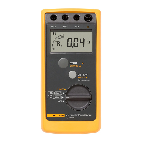
Earth Ground Tester Features Features Refer to Figure 1 and Table 2 for Tester features and functions. evp01.eps Figure 1. Features and Functions... -
Page 14: Features And Functions
1621 Users Manual Table 2. Features and Functions Description H/C2 jack for connection to the auxiliary electrode S/P2 jack for connection to the probe E/C1 jack for connection to the earth ground electrode LCD display (see “LCD Display”) Stand (on back) to prop Tester upright... -
Page 15: Software
Earth Ground Tester Features Software To check the software version, set the rotary switch to OFF, and then press and hold START and set the rotary switch to any On position (3 pole, 2 pole or LIMIT). The software version displays. LCD Display The Tester features a lighted LCD display that shows measurement readings, messages and icons. -
Page 16: Interference Detection
1621 Users Manual Table 3. Display Description and R icons indicate the resistance type being displayed: = Auxiliary electrode resistance = Probe resistance = Earth ground electrode resistance ACTIVE icon indicates a measurement is in progress Digits display measurement results and messages ke icon indicates reading value is in kilohms (x1000) >LIMIT icon indicates measurement value exceeds the set limit or... -
Page 17: Resistance Limit Mode
Earth Ground Tester Features Resistance Limit Mode The Tester has a resistance limit mode that allows you to set a maximum resistance reading. If a resistance reading exceeds the set limit, the Tester beeps and the >LIMIT icon displays. The limit can be set between 0 and 1999 Ω. -
Page 18: Battery Installation
1621 Users Manual Battery Installation The Tester is shipped with a 9 V alkaline (LR61) battery, which you will need to install. When the battery voltage is low, the LO-BAT icon displays, and you will need to replace the battery. -
Page 19: Operating Instructions
Earth Ground Tester Operating Instructions Operating Instructions XW Warning To avoid possible electric shock or personal injury, before powering up and operating the device, carefully read and follow all safety regulations described in “Safety Regulations.” 3-Pole Measurement To perform a 3-pole measurement: 1. - Page 20 1621 Users Manual Aux. Earth Earth Electrode Electrode Probe >20 M (64 FT) >20 M (64 FT) evp03.eps Figure 4. Three-Pole Measurement Setup...
-
Page 21: Ac Resistance Measurement
Earth Ground Tester Operating Instructions AC Resistance Measurement To perform an ac resistance measurement: 1. Set the rotary switch to OFF. 2. Plug a test lead into jack H/C2 and a test lead into jack E/C1. See Figure 5. 3. Connect the test leads to each end of the conductor under test. See Figure 5. -
Page 22: Troubleshooting
1621 Users Manual Troubleshooting To troubleshoot your Tester, follow the steps in Table 4. Table 4. Troubleshooting Step Description Auxiliary electrode resistance (R ) too high If the auxiliary electrode resistance is too high (exceeds 199 ke), it is not possible to drive the current necessary for reliable measurements. -
Page 23: Specifications
Earth Ground Tester Specifications Specifications Note Fluke reserves the right to modify specifications without notice for the purpose of product improvement. Measuring functions: 3-pole earth ground resistance, 2 pole AC resistance of a conductor Interference voltage Intrinsic error: Refers to the reference temperature range and is... - Page 24 1621 Users Manual Temperature Coefficient: ± 0.1 % of range per degree Kelvin Safety: IEC/EN 61010-1, 600VCATII, pollution degree 2 Maximum Deviations: Deviation Parameter Influence Factor influence Position Supply Voltage Temperature E 2.3 % Serial Interference Voltage (20 V) 0.6 %...
- Page 25 Earth Ground Tester Specifications Operating Measuring Resolution Display Intrinsic Uncertainty Range Range Uncertainty IEC 61557* 0.15 to 20 Ω 0.01 Ω 0 to 19.99 Ω ± (6 % of ± (18 % of 200 Ω 0.1 Ω 20 to 199.9 Ω measured measured value value + 5D)
-
Page 26: Storage
Singapore: +65-738-5655 Anywhere in the world: +1-425-446-5500 You may visit us on the World Wide Web at www.fluke.com. To register your product, visit http://register.fluke.com. P OWE R P OI NT E NGI NE E R I NG L t d .
Need help?
Do you have a question about the 1621 and is the answer not in the manual?
Questions and answers