YOKOGAWA YS80 Series User Manual
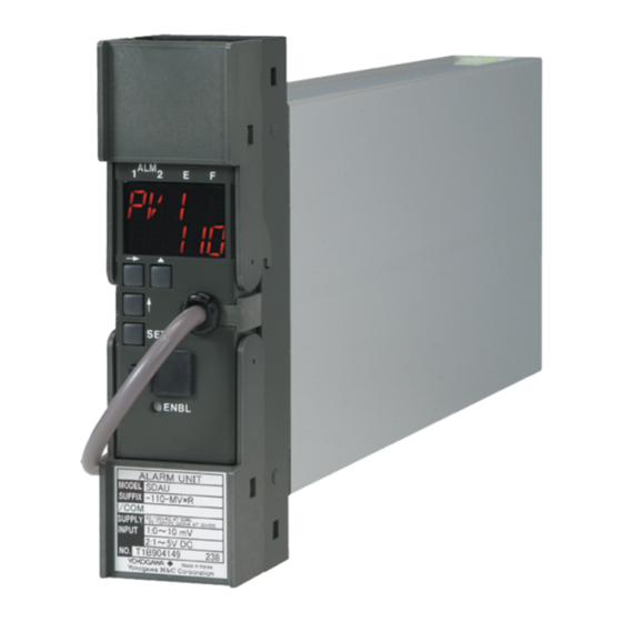
Digital alarm unit
Hide thumbs
Also See for YS80 Series:
- User manual (66 pages) ,
- User manual (42 pages) ,
- Technical information (2 pages)

Related Manuals for YOKOGAWA YS80 Series


Summary of Contents for YOKOGAWA YS80 Series
- Page 1 User’s Manual Model SDAU (Style R) Digital Alarm Unit IM 01B04K03-02E IM 01B04K03-02E 8th Edition...
-
Page 3: Table Of Contents
Toc-1 Model SDAU (Style R) Digital Alarm Unit IM 01B04K03-02E 8th Edition CONTENTS INTRODUCTION .................. 1-1 Inspection ..................... 1-2 Documentation Conventions ............... 1-3 Notice ....................1-4 About Compatibility with the Conventional Model (Style E) ..... 1-6 GENERAL ..................... 2-1 Standard Specifications ............... 2-2 Model and Suffix Codes ................ - Page 4 Toc-2 Parameter Change Disable Function..........5-11 Various Display Modes ..............5-12 5.6.1 Display at Power ON ............... 5-12 5.6.2 LOCK Display ................5-12 5.6.3 Display in Display Shutoff Mode ..........5-12 5.6.4 Error Display ................5-13 5.6.5 Display of Self-Diagnostic Results ........... 5-13 5.6.6 Detailed Alarm Status Display ..........
-
Page 5: Introduction
<1. INTRODUCTION > INTRODUCTION This manual describes the functions and operations of the SDAU Digital Alarm Unit. Intended Readers This manual is intended for personnel in charge of: Installation and wiring Instrumentation and setup of functions Operation and monitoring of the controller ... -
Page 6: Inspection
Alarm Label (Parts No.: L4040JA) ..............1 sheet • • Precautions on the Use of the YS80 Series............ 1 Downloadable Electronic Manuals You can download the latest manuals from the following website: To view the User’s Manuals, use Adobe Acrobat Reader of Adobe Systems Incorporated. -
Page 7: Documentation Conventions
The product has a QR Code pasted for efficient plant maintenance work and asset information management. It enables confirming the specifications of purchased products and user’s manuals. For more details, please refer to the following URL. https://www.yokogawa.com/qr-code QR Code is a registered trademark of DENSO WAVE INCORPORATED. IM 01B04K03-02E 8th Edition: Jan.29,2021-00... -
Page 8: Notice
Read this manual carefully to gain a thorough understanding of how to operate this product before you start using it. This manual is intended to describe the functions of this product. Yokogawa Electric Corporation (hereinafter simply referred to as Yokogawa) does not guarantee that these functions are suited to the particular purpose of the user. - Page 9 Yokogawa does not make any warranties regarding the product except those mentioned in the WARRANTY that is provided separately. Yokogawa assumes no liability to any party for any loss or damage, direct or indirect, caused by the use or any unpredictable defect of the product.
-
Page 10: About Compatibility With The Conventional Model (Style E)
<1. INTRODUCTION > About Compatibility with the Conventional Model (Style E) The operation and function differ from the conventional model. Read this manual carefully to gain a thorough understanding of how to operate this product before you start using it. ... -
Page 11: General
· Copy parameters to other devices of the same model and suffix code. The BT200 BRAIN Terminal of Yokogawa Electric Corporation can also be connected. Modular jack adapter (part no.: E9786WH) is required to connect a PC (VJ77), the JHT200 Handy Terminal or BT200 to the Digital Alarm Unit. -
Page 12: Standard Specifications
<2. GENERAL> Standard Specifications Please see the General Specifications (GS 01B04K03-02E) at the end of this manual. IM 01B04K03-02E 8th Edition: Jan.29,2021-00... -
Page 13: Model And Suffix Codes
<2. GENERAL> Model and Suffix Codes The following table shows the SDAU model and suffix codes. Table 2.1 Model and Suffix Codes Model Suffix Codes Optional Suffix Codes Description SDAU Digital Alarm Unit Input signal 2: 1 to 5 V Input Signal 2 Input signal 2: Universal (Note 3) 1 to 5 V... -
Page 14: Accessory
<2. GENERAL> Accessory Reference junction bracket (For SDAU-120-xx*R/NHR or SDAU-270-xx*R/NHR) Alarm label : 1 Figure 2.2 Location of the Reference Junction Bracket CAUTION • Notice when replacing the internal unit of a conventional model: When replacing the internal unit of a conventional model (SDAU-1xx-xx*E) with that of SDAU- 120-xx*R or SDAU-270-UN*R, a reference junction bracket (for connection to the RJC sensor) needs to be installed (replaced). -
Page 15: Installation
<3. INSTALLATION> INSTALLATION For details of the installation procedure and wiring precautions, refer to the instruction manual “Installation of Rack-Mounted Instruments” (IM 1B4F2-01E). External Wiring (a) All cable ends must be furnished with crimp-on type solderless lugs (for 4mm screws). (b) Draw out the internal unit from the rack case. - Page 16 <3. INSTALLATION> B+ A- Figure 3.2 RS485 Communication Terminal Layout (/COM option) Applicable Cables (1) Signal circuit wiring • Cross-sectional area of the cable conductor: 0.5 to 0.75 mm • Examples of applicable cables: Single core PVC insulated flexible cable (VSF) stranded wires (JIS C 3306);...
-
Page 17: Functions
<4. FUNCTIONS > FUNCTIONS Operation Principle Input signals are converted into digital data by an A/D converter circuit. This digital data is signal processed (such as linearization or square root extraction) by a microprocessor and then computed for alarm detection. Alarm relays are energized or de-energized according to the alarm computation outputs. - Page 18 <4. FUNCTIONS > Internal Function Block Diagram The following shows the internal function block diagram. For more information, see the Description of Each Function section. Input 1 Input 2 Terminal symbol name Input Input Parameter processing processing displayed Alarm detection processing Self- Retransmission Alarm connection/output processing...
-
Page 19: Input Processing Function
<4. FUNCTIONS > Input Processing Function Two input points are provided. The following processing is done with respect to each input (see Figure 4.3). Encircled symbols are parameter symbols appearing on the display setter. "n" takes value 1 or 2. Figure 4.3 Input Processing Function Block Diagram ... - Page 20 <4. FUNCTIONS > • Input range (RHn, RLn): An input range should be set if an input signal is mV or temperature input. If an input value is -6.25% or less, or greater than 106.25% of the input range, an input overrange occurs. For actions to be taken in the event of an input overrange, see Section 8.2, "Actions under Fault Conditions."...
-
Page 21: Alarm Processing Function
<4. FUNCTIONS > Alarm Processing Function As shown in Figure 4.5, the SDAU's alarm function consists of the alarm-detecting sections and alarm connection/output sections, each of which functions independent of the others. Set parameter Rate-of- Rate-of- Parameter to be displayed Deviation change change... -
Page 22: Alarm-Detecting Sections
<4. FUNCTIONS > 4.3.1 Alarm-Detecting Sections There are three alarm-detecting sections, which set each of the following items (see Figure 4.5). Those in parentheses show parameter symbols to be displayed on the display setter. "n" takes value 1, 2, or 3. •... -
Page 23: Alarm Connection/Output Sections
<4. FUNCTIONS > [°C] -20°C +30°C -40°C +30°C +40°C [Sec.] VLn.TM Alarm action Normal Normal Alarm Alarm when n.H = +30°C Alarm action Normal Alarm Normal when n.L = -20°C Figure 4.7 Action to be Taken When Input is Rate-of-change Alarm 4.3.2 Alarm Connection/Output Sections There are two alarm connection/output sections (four for the /RLY4 option), which set... - Page 24 <4. FUNCTIONS > • Alarm output timer (TMn): Sets the alarm output delay for alarm n. The alarm unit outputs an alarm when the time period set in TMn has elapsed after the connection of alarm n resulted in an alarm status. Time can be specified in the range of 0 to 600 seconds (in 1 sec.
- Page 25 <4. FUNCTIONS > • Alarm-n ON delay timer (ON.TMn): Sets dead time after which the alarm turns ON. If an input value is within an alarm range for a time set by ON.TMn, an alarm status occurs. If the input returns to the normal range before the time set by ON.TMn elapses, no alarm turns ON.
-
Page 26: Example Of Setting The Alarm Functions
4-10 <4. FUNCTIONS > 4.3.3 Example of Setting the Alarm Functions Example of Setting 1 Condition A) ALM1: ALM1 alarm is output if all of the following are generated: the high high-limit alarm of input 1 (1H = 80), the high-limit alarm of input 1 (3H = 70), and the high-limit alarm of input 2 (2H = 50). -
Page 27: Retransmission Output Function (For /Vlt And /Cur Options)
4-11 <4. FUNCTIONS > Retransmission Output Function (for /VLT and /CUR Options) The SDAU digital alarm unit with the /VLT or /CUR option can output an input signal as retransmission output in order to use it in a recorder, etc. The retransmission output function is set using the following parameters. -
Page 28: Communication Function (For /Com Option)
4-12 <4. FUNCTIONS > Communication Function (for /COM Option) The SDAU alarm unit can communicate with a device with an RS-485 communication interface, allowing input values to be read out and/or parameters to be read out or written in. For more information, see YS80*R Rack-Mounted Instruments Communication Functions User’s Manual (IM 01B04F01-20E). -
Page 29: Function Of Recovery From Power Failure
4-13 <4. FUNCTIONS > Function of Recovery from Power Failure The SDAU alarm unit's recovery from power failure function operates as described below, depending on the setting of the HOT start/COLD start parameter. HOT start: Continues operation from the alarm status just before a power failure. Note1: When the alarm timer mode is set to alarm output timer, ALM3 and ALM4 cannot be HOT started. -
Page 30: Self-Diagnostic Function
4-14 <4. FUNCTIONS > Self-Diagnostic Function The SDAU alarm unit has a self-diagnostic function capable of detecting a failure or error in the unit itself. If an error/failure is detected, notification is made by the following means: an error indication appears on the lower half of the digital display, a parameter is displayed on the upper half of it, a lamp on the front panel of the alarm unit is lit, the failure output contact is de-energized (when /RLY4, /CUR, or /VLT is not specified), and/or an alarm output contact is activated. -
Page 31: Alarm/Failure Outputs At Power-On And Power Failure
4-15 <4. FUNCTIONS > Alarm/Failure Outputs at Power-on and Power Failure The alarm and failure outputs function as explained below when the power is turned on or if the power fails. The following example explains a case where the action is defined as RLYn ACTION=NRM ENERGIZED (normal-state energization) and no alarms or failures have occurred. - Page 32 Blank Page...
-
Page 33: Setting
<5. SETTING> SETTING WARNING When setting parameters, do not turn off the SDAU alarm unit. Items to Confirm before Start of Operation Before you start operation, inspect and confirm the following items: (1) Draw out the internal unit from the rack case, and make sure that the specified fuses are properly mounted in the fuse holders at the rear of the internal unit. - Page 34 <5. SETTING> (3) Set the Parameters for Optional Suffix Codes (for /VLT, /CUR or /COM only) For details on parameters for “/VLT” or “/CUR” option, refer to Retransmission Output-Related Parameters in Section 6.3, “Display on Front Panel: List of Parameters” or parameter numbers J** SET (RET) in Section 6.4, “BRAIN communication parameter: List of Parameters.”...
-
Page 35: Names Of Components
<5. SETTING> Name of Components The following shows the name of SDAU components. Figure 5.1 Names of Components IM 01B04K03-02E 8th Edition: Jan.29,2021-00... -
Page 36: Part Names Of The Display Setter
<5. SETTING> Part Names of the Display Setter Figure 5.2 Part Names of the Display Setter Note1: When using a PC (VJ77) or the Handy Terminal, connect a PC (VJ77) or the Handy Terminal after removing the RS- 485 connector. Note2: When the /RLY4 option is specified, the ALM3 and ALM4 lamps take the place of the E and F lamps. - Page 37 <5. SETTING> Functions of the Digital Display Section Table 5.1 Functions of the Digital Display Section Display/indication Function Parameter display section Displays a parameter symbol in an 11-segment indication. For the display of letters in 11 segments, see a List of LED Display Symbols in the following table.
-
Page 38: Setting Jumpers
<5. SETTING> Setting Jumpers The SDAU alarm unit has the following jumpers. Table 5.3 Setting Jumpers Name Jumper Name Optional Suffix Parameter write-protect jumper W.P. ― Alarm output contact ALM1 RY.1 With /RLY4 specified action setting jumper ALM2 RY.2 With /RLY4 specified ALM3 RY.3 With /RLY4 specified... -
Page 39: Checking Setting Jumpers And Their Locations
<5. SETTING> 5.3.1 Checking Setting Jumpers and their Locations The setting jumpers are located on the main board of the internal unit. Pull out the internal unit and check the current settings. Moreover, the current status of the parameter write-protect jumper can be checked via a PC (VJ77) or the JHT200 Handy Terminal without pulling the internal unit out. -
Page 40: Change Of Setting Jumper
<5. SETTING> 5.3.2 Change of Setting Jumper Follow the procedure below to change the setting jumpers: (a) Pull the terminal block cover toward you to draw out the internal unit from the rack case. (b) Check the jumpers on the main board of the internal unit and change their settings as desired. -
Page 41: Settings Done From The Front Panel Of The Alarm Unit
<5. SETTING> Settings Done from the Front Panel of the Alarm Unit Using the display setter on the front panel of the alarm unit, you can display input values and set parameters. For more information on the parameters, see Section 6.3, "Display on Front Panel: List of Parameters."... -
Page 42: Settings Using Key Switches (Example)
5-10 <5. SETTING> 5.4.2 Settings Using Key Switches (Example) The following describes how to set a parameter using the key switches. Put the SDAU into a parameter setting-and-change enable state and follow the procedure below to set the parameter. CAUTION If the Parameter Write-Protect jumper on the main board has been set to ON, the SDAU does not advance to the setting change mode even if you press the [→] key switch in step (4) of the parameter setting procedure. -
Page 43: Parameter Change Disable Function
5-11 <5. SETTING> Parameter Change Disable Function The SDAU alarm unit has four parameter-change-disable functions as shown in the table below. They are used to prevent a parameter from being changed inadvertently. Table 5.5 Parameter Change Disable Function How to set disable function How to cancel disable Operations to be disabled function... -
Page 44: Various Display Modes
5-12 <5. SETTING> Various Display Modes This section describes various display modes. 5.6.1 Display at Power ON The model with display setter displays REV NO. (revision number of software for the SDAU) for about 2 seconds after power ON. Example of display (REV NO.2) 5.6.2 LOCK Display If the upper half of the digital display shows "LOCK,"... -
Page 45: Error Display
5-13 <5. SETTING> 5.6.4 Error Display When the upper half of the digital display shows a PV parameter (PVn, DV, PVn.VL), the lower half of the digital display indicates an error description. For more information, see Section 8.2, "Actions under Fault Conditions." Figure 5.8 Error Display 5.6.5... -
Page 46: Detailed Alarm Status Display
5-14 <5. SETTING> 5.6.6 Detailed Alarm Status Display The detailed alarm status display shows the type of input for which alarm has occurred and the relevant alarm setpoint. To switch to the detailed alarm status display, press the [→] key switch while the alarm status is "1."... - Page 47 5-15 <5. SETTING> Figure 5.11 Detailed Alarm Status Display The detailed alarm status display and its display procedure are as shown below when parameters in the table are set in an input condition as shown in the figure above. For setting 1: No change (right arrow key switch is disabled because ALM1 = 0) →...
-
Page 48: Settings Using The Jht200 Handy Terminal
To display or set/change a parameter, connect the JHT200 Handy Terminal (*1) to this unit. *1: The BT200 BRAIN Terminal of Yokogawa Electric Corporation can also be used. CAUTION For details of operation and adjusting procedures of JHT200 Handy Terminal, refer to the instruction manual “JHT200 Handy Terminal”... -
Page 49: Settings Using A Pc (Vj77)
5-17 <5. SETTING> Settings Using a PC (VJ77) The SDAU alarm unit has BRAIN communication parameters used to specify a function or to adjust inputs/outputs. To display or set/change a parameter, connect a PC (VJ77) to this unit. CAUTION For details of operation and adjusting procedures of VJ77 Parameters Setting Tool, refer to the instruction manual “Model VJ77 PC-based Parameters Setting Tool”... - Page 50 Blank Page...
-
Page 51: Parameters
<6. PARAMETERS > PARAMETERS Configuration of Parameters The SDAU's parameters include display-only parameters (those shown in the shaded areas of the parameter chart) and parameters that can be set and changed. A parameter can be set in two ways: one is to set it using the key switches and the other is to set it via a PC (VJ77) or the JHT200 Handy Terminal. -
Page 52: Display On Front Panel: Development View Of Parameters
<6. PARAMETERS > Display on Front Panel: Development View of Parameters SDAU-1xx Type Parameters (From "SET" on the next page) Setting of MODn determines the parameters to be displayed (PV1 PV1.VL (To "F1" on the next page) and PV2 are always displayed) Parameter DV is displayed also when parameter RET=3 (PV1-PV2) PV2.VL ALM1... - Page 53 <6. PARAMETERS > Parameter to be displayed only Additional parameter from SDAU*E Parameter changed from SDAU*E Alarm Connection/ Alarm Detection-Related Input-Related Parameters Output Parameters Parameters TM.M MOD1 (From the previous page) /COM Input 1 signal: provided? 1-5 V? AL1_H TC or RTD 1 to 5V Type of input-1 AL1_L...
- Page 54 <6. PARAMETERS > SDAU-270 Type Parameters (From "SET" on the next page) Setting of MODn determines the parameters to be displayed (PV1 and PV1.VL (To "F1" on the next page) PV2 are always displayed) Parameter DV is displayed also when parameter RET=3 (PV1-PV2) PV2.VL ALM1 ALM2...
- Page 55 <6. PARAMETERS > Parameter to be displayed only Additional parameter from SDAU*E Parameter changed from SDAU*E Alarm Connection/Output Alarm Detection-Related Input-Related Parameters Parameters Parameters TM.M MOD1 (From the previous page) /COM WNGR1 provided? SNSR1 WNGR2 AL1_H DSPM AL1_L SNSR1? AN.OR.1 Mode1 = Rate-of- ACT1 change alarm?
-
Page 56: Display On Front Panel: List Of Parameters
<6. PARAMETERS > Display on Front Panel: List of Parameters There are parameters that are not displayed depending on the model, optional suffix code, or parameter's setpoint. For more information, see Section 6.2, "Display on Front Panel: Development View of Parameters." When selecting a parameter for a choice using RS-485 communication, set a value given in the Description column in the table below. - Page 57 <6. PARAMETERS > Input-Related Parameters Symbol appearing on Name Description Setting Initial digital display (Parameter Range Value Name) SDAU*E SDAU*R → Input-1 filter Sets first-order lag filter with respect to input 0.0 to 200.0 0.0 sec. (Same as sec. right) Approx.
- Page 58 <6. PARAMETERS > Symbol appearing on Name Description Setting Initial digital display (Parameter Range Value Name) SDAU*E SDAU*R Low limit of When input 1 is mV or temperature input, this (See the (See the input-1 range parameter sets the low limit of the input-1 Description Description range.
- Page 59 <6. PARAMETERS > Symbol appearing on Name Description Setting Initial digital display (Parameter Range Value Name) SDAU*E SDAU*R Input-2 filter Sets first-order lag filter with respect to input 0.0 to 200.0 → (Same as sec. right) (Details are the same as those of input-1 filter.) SNSR2 Sensor type 2...
- Page 60 6-10 <6. PARAMETERS > Symbol appearing on Name Description Setting Initial digital display (Parameter Range Value Name) SDAU*E SDAU*R BIAS2 Input-2 bias Adds bias value to a value obtained after (See the input processing and displays it as PV2. Description Setting range: -19999 to 32000 column.) Where, engineering unit span (EUS) =...
- Page 61 6-11 <6. PARAMETERS > Alarm Connection/Output Parameters Symbol appearing on Name Description Setting Initial digital display (Parameter Range Value Name) SDAU*E SDAU*R TM.M Alarm timer Sets alarm timer mode. 0, 1 mode 0: Alarm output timer (which delays alarm output, equivalent to SDAU*E.) 1: ON/OFF delay timer (alarm dead time) AL1_H...
- Page 62 6-12 <6. PARAMETERS > Symbol appearing on Name Description Setting Initial digital display (Parameter Range Value Name) SDAU*E SDAU*R AL2_L Low-limit alarm Sets connection of a low limit alarm to be 000 to 111 connection of output as alarm 2. alarm 2 (Details are the same as those of the low- limit alarm connection of alarm 1.)
- Page 63 6-13 <6. PARAMETERS > Symbol appearing on Name Description Setting Initial digital display (Parameter Range Value Name) SDAU*E SDAU*R ON.TM4 Alarm-4 ON Sets dead time between the instant alarm-4 0 to 999 sec. 0 sec. delay timer becomes activated and the instant an alarm is output.
- Page 64 6-14 <6. PARAMETERS > Alarm Detection-Related Parameters Symbol appearing on Name Description Setting Initial digital display (Parameter Range Value Name) SDAU*E SDAU*R → MOD1 Input mode 1 Sets a target input at alarm detection 1. 0 to 4 (Same as 0: Input 1 right) 1: Input 2...
- Page 65 6-15 <6. PARAMETERS > Symbol appearing on Name Description Setting Initial digital display (Parameter Range Value Name) SDAU*E SDAU*R HYS1 Hysteresis 1 Sets hysteresis at alarm detection 1. For 0 to 32000 (See the the scale of reference, see Table 6.1. (See the Description Setting range: 0 to 100% of engineering...
- Page 66 6-16 <6. PARAMETERS > Symbol appearing on Name Description Setting Initial digital display (Parameter Range Value Name) SDAU*E SDAU*R MOD3 Input mode 3 Sets a target input at alarm detection 3. 0 to 4 → (Same as (Details are the same as those of input right) mode 1.) →...
- Page 67 6-17 <6. PARAMETERS > Communication-Related Parameters (for /COM Option) Symbol appearing on Name Description Setting Initial digital display Range Value SDAU*E SDAU*R Protocol selection Specifies communication protocol 0 to 4 0: PC link 1: PC link (with checksum) 2: Ladder communication 3: MODBUS (ASCII) 4: MODBUS (RTU) Communication...
- Page 68 6-18 <6. PARAMETERS > Retransmission Output-Related Parameters (for /VLT or /CUR Option) Symbol appearing on Name Description Setting Initial digital display Range Value SDAU*E SDAU*R Selection of Specifies input to be output as 0 to 3 retransmission retransmission output. output type 0: Does not use retransmission output.
- Page 69 6-19 <6. PARAMETERS > Adjustment-related Parameters Symbol appearing on Name Description Setting Initial digital display Range Value SDAU*E SDAU*R WNGR1 Correction of Corrects the wire resistance of input 1. 0, 1 input-1 wire 0: RESET resistance 1: EXECUTE Note 1: This parameter is initialized if BURNOUT1, SENSOR TYPE1, TC TYPE1, or RTD TYPE1 changes.
- Page 70 This parameter is not provided for a PC (VJ77) or the JHT200 Handy Terminal. Take care not to forget the set password. To cancel a password, contact your nearest YOKOGAWA representative. (Note that this is a charged service.) IM 01B04K03-02E 8th Edition: Jan.29,2021-00...
- Page 71 6-21 <6. PARAMETERS > Table 6.1 Scale of Reference MODn= 0: PV1 1: PV2 2: Deviation DP1 ≤ DP2 DP1 > DP2 Scale SCH1, SCL1 SCH2, SCL2 SCH1, SCL1 SCH2, SCL2 If the span of a deviation ((SCH1 - SCL2) - (SCL2 - SCH2)) exceeds the range of -19999 to 32000 in MODn=2: Deviation, the initial value and limit value of HYSn are determined by regarding the span of a deviation as -19999 or 32000.
-
Page 72: Brain Communication: List Of Parameters
6-22 <6. PARAMETERS > BRAIN Communication: List of Parameters CAUTION The SET parameters and PASS parameter cannot be displayed or set using a PC (VJ77) or the JHT200 Handy Terminal. If any parameter value is read using a PC (VJ77) or the Handy Terminal with the Parameter Write Protect jumper (W.P.) set to ON, the data lines of parameters with the value 0 become blank. - Page 73 6-23 <6. PARAMETERS > Symbol Appearing BRAIN Communication Parameters on Digital Display Symbol Display Item Description Display Condition DISPLAY2 Display 2 INPUT1 Details are the same as for those of the equivalent item in A. The display is periodically updated. INPUT2 PV1.VL PV1.VL...
- Page 74 6-24 <6. PARAMETERS > Symbol Appearing BRAIN Communication Parameters on Digital Display Symbol Display Item Description Setting Initial Value Display Range Condition RT TP1 See Display on Front Panel: List See Display on SENSOR - Pt100-90 TYPE1 of Parameters. Front Panel: TYPE1 = RTD (ITS-90, JIS’97) List of...
- Page 75 6-25 <6. PARAMETERS > Symbol Appearing BRAIN Communication Parameters on Digital Display Symbol Display Item Description Setting Range Initial Value Display Condition See Display on Front Panel: List of Parameters. Input 2 is any input other than 1- 5 V. Input 2 is any input other than 1-...
- Page 76 6-26 <6. PARAMETERS > Symbol Appearing BRAIN Communication Parameters on Digital Display Symbol Display Item Description Setting Range Initial Value Display Condition SET (ALM) Setting (alarm) TM.M TIMER See Display on Front Panel: List - DELAY.T See Display on Always MODE of Parameters.
- Page 77 6-27 <6. PARAMETERS > Symbol Appearing BRAIN Communication Parameters on Digital Display Symbol Display Item Description Setting Range Initial Value Display Condition ON.TM1 See Display on Front Panel: List of Parameters TIMER DELAY1 MODE = ON.OFF.T OF.TM1 TIMER DELAY1 MODE = ON.OFF.T AL2_H AL2_H...
- Page 78 6-28 <6. PARAMETERS > Symbol Appearing BRAIN Communication Parameters on Digital Display Symbol Display Item Description Setting Range Initial Value Display Condition MOD1 MOD1 See Display on Front Panel: List - PV1 See Display on Always of Parameters. - PV2 Front Panel: List displayed - PV1 - PV2...
- Page 79 6-29 <6. PARAMETERS > Symbol Appearing BRAIN Communication Parameters on Digital Display Symbol Display Item Description Setting Initial Value Display Range Condition SET (ALM Setting H/L) (alarm) See Display on Front Panel: List of Parameters. When 1H is connected to one of AL1_H, AL2_H, AL3_H, or...
- Page 80 6-30 <6. PARAMETERS > Symbol Appearing BRAIN Communication Parameters on Digital Display Symbol Display Item Description Setting Initial Value Display Range Condition SET (COM) Setting (RS-485) PROTOCOL See Display on Front Panel: - PC LINK See Display /COM List of Parameters. - PC LINK on Front WITH SUM...
- Page 81 6-31 <6. PARAMETERS > Symbol Appearing BRAIN Communication Parameters on Digital Display Symbol Display Item Description Setting Initial Value Display Condition Range OUT1 0% Output-1 Adjust 0% of -20.00 to /VLT or /CUR retransmission 20.00% correction output. OUT1 100% Output-1 Adjust 100% of -20.00 to /VLT or /CUR...
- Page 82 Blank Page...
-
Page 83: Maintenance
This chapter describes the calibration procedures that can be done in the instrument room or service shop. Test Equipments For efficient maintenance of this alarm unit, it is recommended that the user have the following test equipment manufactured by Yokogawa or their equivalent. Device Model Name Number... -
Page 84: Input Adjustment
<7. MAINTENANCE> 7.3.1 Input Adjustment Adjustment using key switches This adjustment uses the CALn.Z and CALn.S parameters (for the case of 1-5 V input only). Connect devices as shown in the figure below, turn on the power of each device, and warm up the devices for approx. - Page 85 <7. MAINTENANCE> YOKOGAWA Type Yokogawa GS200 7651 or equivalent or the equivalent + DC Voltage/ - 2 4 6 Current Standard Power Supply Figure 7.1 Wiring for mV DC Input Adjustment YOKOGAWA Type Yokogawa GS200 7651 or equivalent or the equivalent +...
-
Page 86: Correction Of Input Wiring Resistance
<7. MAINTENANCE> 7.3.2 Correction of Input Wiring Resistance If an error occurs because of input wiring resistance when mV DC, thermocouple or RTD input, or if using a safety barrier such as BARD and the like with the instrument, input wiring resistance can be corrected by parameter using a PC (VJ77) or JHT200 Handy Terminal. - Page 87 <7. MAINTENANCE> Style-R SDAU (When connecting BARD300 BARD300 Style-R SDAU BARD700 BARD700 BARD to input 2) (When connecting BARD to input 1) R1 and R2 denote balanced R1 and R2 denote balanced internal resistance. internal resistance. Figure 7.4 Connection between BARD and an Alarm Unit with RTD Input IM 01B04K03-02E 8th Edition: Jan.29,2021-00...
-
Page 88: Check Of Reference Junction Temperature Compensation Action
SDAU-270-UN*R, a case terminal fitting (for connection to the RJC sensor) needs to be installed (replaced). For this, see Section 2.3, "Accessory." r: Resistance equivalent to that of the actual lead wire Thermocouple element or compensating lead wire YOKOGAWA Type Yokogawa GS200 2553 or equivalent Copper Wire or the equivalent +... -
Page 89: List Of Replaceable Parts
L3040YJ: Option codes deterioration from temperature and other /TB、/FBP, or /REK operating conditions, we recommend the L3040YS: Option /A2ER replacement period on the left. Note: For the option /TB/A2, please contact YOKOGAWA's sales office or sales representative. IM 01B04K03-02E 8th Edition: Jan.29,2021-00... - Page 90 Blank Page...
-
Page 91: Troubleshooting
<8. TROUBLESHOOTING > 8. TROUBLESHOOTING If any fault occurs in the instrument, note the symptoms and follow Section 8.1. IM 01B04K03-02E 8th Edition: Jan.29,2021-00... -
Page 92: Actions Under Fault Conditions
CHECK Error event of diagnostic Info error *2 result *3 CPU failure: Lamp lit: F lamp WDT error Contact YOKOGAWA' Internal Alarm output contacts: s sales office All de-energized or sales representative Failure output contact: De-energized. Key switches: Disabled Communication:... - Page 93 *2 result *3 Display Lamp lit: All OFF Faulty Contact board Failure output contact: display YOKOGAWA's failure Energized, and alarm board sales office or detection and alarm sales output action continue. representative. Key switches: Disabled Communication:...
- Page 94 <8. TROUBLESHOOTING > FLAG Digital Display BRAIN Cause of Operation Cause Remedy Communication Error Parameter Display Indication Display of SELF Detailed in the self- CHECK Error case of diagnostic Info.* 4 error *2 result *3 0800 ERROR INPUT1 Input-1 Lamp lit: E-lamp When A/D Connect BURN...
- Page 95 <8. TROUBLESHOOTING > FLAG Digital Display BRAIN Cause of Operation Cause Remedy Communication Error Parameter Display Indication Display of SELF Detailed in the self- CHECK Error case of diagnostic Info.* 4 error *2 result *3 0040 ERROR HOT start Lamp lit: E-lamp Only when Turn on START...
- Page 96 Blank Page...
-
Page 97: Power Supply Terminal Connectins (Options /Tb, /Tb/A2 And /Rek)
<9. POWER SUPPLY TERMINAL CONNECTIONS (Options /TB, /TB/A2 and /REK)> POWER SUPPLY TERMINAL CONNECTIONS (Options /TB, /TB/A2 and /REK) If you specify the terminal block to which the power source is directly connected (option codes: /TB, /TB/A2 and /REK), the external wiring to the terminal block is necessary;... -
Page 98: Names Of Components And Power Terminal Symbols
<9. POWER SUPPLY TERMINAL CONNECTIONS (Options /TB, /TB/A2 and /REK)> Names of Components and Power Terminal Symbols Figure 9-1 Names of Parts and Power Terminal IM 01B04K03-02E 8th Edition: Jan.29,2021-00... -
Page 99: Power Supply And Ground Wiring
<9. POWER SUPPLY TERMINAL CONNECTIONS (Options /TB, /TB/A2 and /REK)> Power Supply and Ground Wiring (1) All cable ends must be furnished with crimp-on type solderless lugs (for 4 mm screws). (2) Examples of applicable cables: Cross-sectional area of the cable conductor: 2.0 mm For the power supply, use cable having a cross-sectional area of at least 1.25 mm Applicable cable: 600 V PVC insulated cable (IV) stranded wires, conforming to JIS C3307. - Page 100 Blank Page...
-
Page 101: General Specifications
· Save read parameters to a file (tungsten95% rhenium5%-tungsten74% · Copy parameters to other devices of the same model rhenium26%) and suffix code. RTD Input The BT200 BRAIN Terminal of YOKOGAWA Input Signal Measuring Range (°C) Electric Corporation can also be connected. JPt100 (JIS’89) -200.0 to 510.0 °C... - Page 102 Two sets of transfer contacts or Contact Four sets of NC or NO contacts when /RLY4 option is selected. Indicator Lamp Yellow lamp (ALMn) lights up on alarm. All Rights Reserved. Copyright © 2004, Yokogawa Electric Corporation GS 01B04K03-02E Jan.12, 2021-00...
- Page 103 Alarm Output 1 Note 1: Select one of them to use. Note 2: Any of six types of HI Alarm / LO Alarm can be connected. F01.ai All Rights Reserved. Copyright © 2004, Yokogawa Electric Corporation GS 01B04K03-02E Jan.12, 2021-00...
- Page 104 The adapter for modular jack (E9786WH) is required for connecting a PC (VJ77), the JHT200 Handy Terminal or BT200 to the Digital Alarm Unit. (3) RS-485 Communication (when /COM option is specified) All Rights Reserved. Copyright © 2004, Yokogawa Electric Corporation GS 01B04K03-02E Jan.12, 2021-00...
- Page 105 Types R and S: 1°C (2) Multiply the value in (1) by K, where K=(Thermocouple output change/°C near normal temperature) ÷ (Thermocouple output change /°C near input temperature.) All Rights Reserved. Copyright © 2004, Yokogawa Electric Corporation GS 01B04K03-02E Jan.12, 2021-00...
- Page 106 Retransmission output accuracy guaranteed range is within the range above and within 0.0% to 100.0% of span. ACCESSORIES Label sheet: 1 sheet Reference junction bracket : For SDAU-120-xx*R/NHR or SDAU-270-xx*R/NHR All Rights Reserved. Copyright © 2004, Yokogawa Electric Corporation GS 01B04K03-02E Jan.12, 2021-00...
- Page 107 Note: There is no difference between the latest and the previous temperature tables as far as applying them to the YEWSERIES. - TC: Latest version; IEC60584-1: 2013/JIS C1602:2015 Previous version; IEC60584-1: 1995/JIS C1602:1995 - RTD Latest version; IEC60751- 2008/JIS C1604:2013 Previous version; IEC751- 1995/JIS C1604:1997 All Rights Reserved. Copyright © 2004, Yokogawa Electric Corporation GS 01B04K03-02E Jan.12, 2021-00...
- Page 108 *2: Switch NC/NO using jumper. NC: Relay normally closed contact (closed when relay de-energized). NO: Relay normally open contact (open when relay de-energized). F02.ai ● RS485 Communication Terminals (/COM Option) F03.ai All Rights Reserved. Copyright © 2004, Yokogawa Electric Corporation GS 01B04K03-02E Jan.12, 2021-00...
- Page 109 F04.ai ● Power Supply Terminal Type Without/COM With/COM El e ctri c El e ctri c Power supply terminals F05.ai All Rights Reserved. Copyright © 2004, Yokogawa Electric Corporation GS 01B04K03-02E Jan.12, 2021-00 Subject to change without notice.
- Page 111 July 15, 2020/7th Edition QR code description and error correction. Jan. 29, 2021/8th Edition VJ77 parameter setting tool (R3.01 or later) support Written by Yokogawa Electric Corporation Published by Yokogawa Electric Corporation 2-9-32 Nakacho, Musashino-shi, Tokyo 180-8750, Japan IM 01B04K03-02E 8th Edition: Jan.29,2021-00...
- Page 112 3F Tower D Cartelo Crocodile Building, No.568 West Tianshan Road, Shanghai 200335, CHINA Phone : 86-21-62396262 Fax : 86-21-62387866 YOKOGAWA ELECTRIC KOREA CO., LTD. (Yokogawa B/D, Yangpyeong-dong 4-Ga), 21, Seonyu-ro 45-gil, Yeongdeungpo-gu, Seoul, 07209, KOREA Phone : 82-2-2628-6000 Fax : 82-2-2628-6400 YOKOGAWA ENGINEERING ASIA PTE. LTD.
Need help?
Do you have a question about the YS80 Series and is the answer not in the manual?
Questions and answers