Table of Contents
Advertisement
Quick Links
Download this manual
See also:
Programming Manual
Advertisement
Table of Contents
Troubleshooting

Related Manuals for Rigol DS1000 Series


Summary of Contents for Rigol DS1000 Series
- Page 1 User’s Guide RIGOL Publication number UGA02107-1110 Dec. 2009 DS1000 Series Digital Oscilloscopes © 2006 RIGOL Technologies, Inc. All Rights Reserved.
- Page 3 Information in this publication replaces all previous corresponding material. RIGOL reserves the right to modify or change part of or all the specifications and pricing policies at company‟s sole decision. NOTE: RIGOL is registered trademark of RIGOL Technologies, Inc.
-
Page 4: Safety Notices
Avoid Circuit or Wire Exposure. Do not touch exposed connections and components when power is on. Do Not Operate With Suspected Failures. If suspected damage occurs with the © 2006 RIGOL Technologies, Inc. User‟s Guide for DS1000 Series... - Page 5 Keep product surfaces clean and dry The disturbance test of all the models meet the limit values of A in the standard of EN 61326: 1997+A1+A2+A3, but can’t meet the limit values of © 2006 RIGOL Technologies, Inc. User‟s Guide for DS1000 Series...
- Page 6 RIGOL Measurement Category The DS1000 series Digital Oscilloscope is intended to be used for measurements in Measurement Category I. Measurement Category Definitions Measurement Category I is for measurements performed on circuits not directly connected to MAINS. Examples are measurements on circuits not derived from MAINS, and specially protected (internal) MAINS derived circuits.
-
Page 7: Safety Terms And Symbols
CAUTION: indicates that a potential damage to the instrument or other property might occur. Symbols on the Product: These symbols may appear on the Instrument: Test Grounding Hazardous Refer to Protective Grounding Terminal Voltage Instructions Earth Terminal Terminal of Chassis © 2006 RIGOL Technologies, Inc. User‟s Guide for DS1000 Series... - Page 8 General-Purpose Oscilloscopes RIGOL DS1000-Series Digital Oscilloscopes offer exceptional waveform viewing and measurements in a compact, lightweight package. The DS1000 series is ideal for production test, field service, research, design, education and training involving applications involving analog/digital circuits test and troubleshooting, as well as education and training.
- Page 9 Pop-up menu makes it easy to read and easy to use Built-in Chinese and English help system Easy-to-use file system supports Chinese & English characters key-in © 2006 RIGOL Technologies, Inc. User‟s Guide for DS1000 Series...
- Page 10 To offer some methods to help users to solve the truobles during operations. Chapter 5 Specifications List common specifications and characteristics of DS1000 series oscilloscope. Chapter 6 Appendix Information about accessories, warranties, services and supports and the like.
-
Page 11: Table Of Contents
Example 7: Triggering on a Video Signal ..........3-10 Example 8: FFT Cursor measurement ............3-12 Example 9: Pass/Fail Test ................ 3-13 Example 10: Triggering on a Digital Signal ..........3-14 © 2006 RIGOL Technologies, Inc. User‟s Guide for DS1000 Series... - Page 12 Troubleshooting ..................4-3 Chapter5 Specifications ..............5-1 Chapter6 Appendix ................6-1 Appendix A: DS1000 Series Accessories ............. 6-1 Appendix B: Warranty ................6-2 Appendix C: General Care and Cleaning ............. 6-3 Appendix D: Contact RIGOL ..............6-4 Index ....................... 1 ©...
-
Page 13: Chapter1 Quick Start
To use digital leads (DS1000xD only) To display a signal automatically To set up the vertical system To set up the horizontal system To trigger the oscilloscope © 2006 RIGOL Technologies, Inc. User‟s Guide for DS1000 Series... -
Page 14: The Front Panel And The User Interface
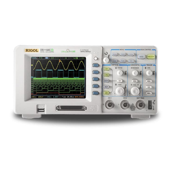
Figure 1-1 Front Panel of DS1000-Series Oscilloscope © 2006 RIGOL Technologies, Inc. User‟s Guide for DS1000 Series... - Page 15 SCALE knobs. denotes the LEVEL knob. The name with a drop shadow denotes the menu operating key, such as WAVEFORM soft key in STORAGE menu. © 2006 RIGOL Technologies, Inc. User‟s Guide for DS1000 Series...
- Page 16 Digital channel Running status turned on turned off Channel 1 Digital channels Horizontal Channel coupling Trigger time base div. and vertical div. offset Figure 1-4 User Interface (Analog and Digital channels) © 2006 RIGOL Technologies, Inc. User‟s Guide for DS1000 Series...
-
Page 17: To Inspect The Instrument
Representative. If the shipping container is damaged, or the cushioning materials show signs of stress, notify the carrier as well as the RIGOL sales office. Keep the shipping materials for the carrier‟s inspection. RIGOL offices will arrange for repair or replacement at RIGOL‟s option without waiting for claim settlement. -
Page 18: To Perform A Functional Check
Align the slot in the probe connector with the key on the CH 1 BNC. Push to connect, and twist to the right to lock the probe in place. Attach the probe tip and ground lead to the PROBE COMP connector. © 2006 RIGOL Technologies, Inc. User‟s Guide for DS1000 Series... - Page 19 ④ Push the OFF button or push the CH1 button again to turn off Channel 1. Push the CH2 button to turn on channel 2, repeat steps 2 and 3. © 2006 RIGOL Technologies, Inc. User‟s Guide for DS1000 Series...
-
Page 20: To Compensate Probes
WARNNING: To avoid electric shock while using the probe, be sure the perfection of the insulated cable, and do not touch the metallic portions of the probe head while it is connected with a voltage source. © 2006 RIGOL Technologies, Inc. User‟s Guide for DS1000 Series... -
Page 21: To Use Digital Leads (Ds1000Xd)
It is unnecessary to switch off power supply of your oscilloscope connect the cable. Figure 1-10 Digital Channel Interface CAUTION: Use only FC1868, LH1116, TC1100 and LC1150 made by RIGOL for specified DS1000xDs. © 2006 RIGOL Technologies, Inc. User‟s Guide for DS1000 Series... - Page 22 4. Test your device with the clip. Figure 1-12 Digital Channel Measurement 5. Remember to connect Ground Channel to the DUT‟s ground terminal. Figure 1-13 Connecting to the Ground 1-10 © 2006 RIGOL Technologies, Inc. User‟s Guide for DS1000 Series...
-
Page 23: To Display A Signal Automatically
2. Press AUTO. The oscilloscope may change the current settings to display the signal; adjusts the vertical and horizontal scaling, the trigger coupling, type, position, slope, level, and mode. © 2006 RIGOL Technologies, Inc. 1-11 User‟s Guide for DS1000 Series... -
Page 24: To Set Up The Vertical Window
If the channel is AC coupled, the DC component of the signal is blocked, allow you to use greater sensitivity to display the AC component of the signal. 1-12 © 2006 RIGOL Technologies, Inc. User‟s Guide for DS1000 Series... - Page 25 Fine or Coarse status. Press OFF button to turn off the channel. Coarse/Fine Shortcut key The Coarse/Fine vertical control can be set by simply pressing the vertical knob. © 2006 RIGOL Technologies, Inc. 1-13 User‟s Guide for DS1000 Series...
-
Page 26: To Set Up The Horizontal System
Delayed Scan mode and it is equal to the following menu operations, MENU→Delayed→ON. 1-14 © 2006 RIGOL Technologies, Inc. User‟s Guide for DS1000 Series... -
Page 27: Horizontal Position Control
To enter or exit the Delayed Scan mode, set the display to Y-T, X-Y or ROLL mode, and turn the horizontal knob to adjust trigger offset. Horizontal position control Trig-Offset: In this setting, the trigger position will be changed horizontally when you turn the knob. © 2006 RIGOL Technologies, Inc. 1-15 User‟s Guide for DS1000 Series... -
Page 28: To Trigger The Oscilloscope
The trigger control window 1. Turn the trigger Level knob and notice the changes on the display. On the DS1000 series oscilloscopes, as you turn the knob or pressing the 50% button, two things will happen on the display for a short time. - Page 29 This function helps to view complex signals such as an AM waveform. Press Holdoff button to activate ( ) knob, then turn it to adjust Holdoff time. © 2006 RIGOL Technologies, Inc. 1-17 User‟s Guide for DS1000 Series...
-
Page 31: Chapter2 Operating Your Oscilloscope
( Storage) To set up utility ( Utility) To measure automatically ( Measure) To measure with cursors ( Cursor) To use run control buttons ( AUTO, RUN/STOP) © 2006 RIGOL Technologies, Inc. User‟s Guide for DS1000 Series... -
Page 32: Understand The Vertical System
100X vertical scale readout correct 500X 1000X Setup digital filter (See table 2-4) Digital filter Go to the next menu page (The followings are the same, no more explanation) © 2006 RIGOL Technologies, Inc. User‟s Guide for DS1000 Series... - Page 33 Defines a 1-2-5 sequence. Volts/Div To change the resolution to small Fine steps between the coarse settings. Turn on the invert function. Invert Restore to original display of the waveform. © 2006 RIGOL Technologies, Inc. User‟s Guide for DS1000 Series...
- Page 34 Figure 2-3 Waveform display Press CH1→Coupling→DC, to set “DC” coupling. It will pass both AC and DC components of the input signal. The waveform is displayed as Figure 2-4: © 2006 RIGOL Technologies, Inc. User‟s Guide for DS1000 Series...
- Page 35 Waveform display Press CH1→Coupling→GND, to set “GND” coupling, it disconnects the input signal. The screen displays as Figure 2-5: GND coupling setup GND coupling status symbol Figure 2-5 Screen display © 2006 RIGOL Technologies, Inc. User‟s Guide for DS1000 Series...
- Page 36 Turn off the BW limit Press CH1→BW Limit→ON, to set up bandwidth limit to “ON” status. It will reject the frequency component higher than 20MHz. The waveform is displayed as Figure 2-7: © 2006 RIGOL Technologies, Inc. User‟s Guide for DS1000 Series...
- Page 37 RIGOL 20M BW limit Mark of BW limit Figure 2-7 Turn on the BW limit © 2006 RIGOL Technologies, Inc. User‟s Guide for DS1000 Series...
- Page 38 Figure 2-8 show an example for using a 1000:1 probe and its attenuation factor. Probe attenuation Vertical volt/div. Figure 2-8 Using a 1000:1 probe Table 2-3 Probe setting Probe attenuation Corresponding settings factors 10:1 50:1 100:1 100X 500:1 500X 1000:1 1000X © 2006 RIGOL Technologies, Inc. User‟s Guide for DS1000 Series...
- Page 39 It will be helpful to adjust the waveform in smooth steps. Fine adjustment Fine adjustment data Figure 2-9 Fine configurations Coarse/Fine Shortcut key: To change Coarse/Fine setting, not only by menu but also by pressing vertical knob © 2006 RIGOL Technologies, Inc. User‟s Guide for DS1000 Series...
- Page 40 When the oscilloscope is triggered on the inverted signal, the trigger is also inverted. Figure 2-10 and 2-11 show the changes after inversion. Invert OFF Figure 2-10 The waveform before inversion Invert ON Figure 2-11 The waveform after inversion 2-10 © 2006 RIGOL Technologies, Inc. User‟s Guide for DS1000 Series...
- Page 41 Press CH1→Digital filter, display the digital filter menu. Turn ( ) knob to set high and low limit of frequency. Figure2-12 Turn off Digital Filter Figure2—13 Turn on Digital Filter © 2006 RIGOL Technologies, Inc. 2-11 User‟s Guide for DS1000 Series...
- Page 42 ) knob to set high limit <frequency> Lower limit Turn ( ) knob to set low limit <frequency> Back to higher level menu (The followings are the same, no more explanation) 2-12 © 2006 RIGOL Technologies, Inc. User‟s Guide for DS1000 Series...
-
Page 43: Math Functions
Fast Fourier Transform Source A Define CH1 or CH2 as source A Source B Define CH1 or CH2 as source B Invert the MATH waveform. Invert Restore to original waveform display. © 2006 RIGOL Technologies, Inc. 2-13 User‟s Guide for DS1000 Series... -
Page 44: Using The Fft
To display FFT waveforms with a large dynamic range, use the dBVrms scale. The dBVrms scale displays component magnitudes using a log scale. 2-14 © 2006 RIGOL Technologies, Inc. User‟s Guide for DS1000 Series... - Page 45 RIGOL Selecting an FFT Window DS1000 series oscilloscopes provide four FFT windows. Each window is a trade-off between frequency resolution and amplitude accuracy. What you want to measure and your source signals characteristics help determine which window to use. Use the following guidelines to select the best window.
-
Page 46: Using Ref
Location External Select memory location out scope Save REF waveform to outer memory Save location Import Go to import menu(see table 2-14) Reset Reset REF waveform Import and Export 2-16 © 2006 RIGOL Technologies, Inc. User‟s Guide for DS1000 Series... - Page 47 2-11) Import the REF file to internal Import memory Delete Delete file File The figure of import and export as following Figure 2-21 Import of export the figure © 2006 RIGOL Technologies, Inc. 2-17 User‟s Guide for DS1000 Series...
- Page 48 Menu Settings Comments Move the cursor up Move the cursor down To delete chosen letter Save Execute the operation The figure of export as following. Figure 2-23 Figure export 2-18 © 2006 RIGOL Technologies, Inc. User‟s Guide for DS1000 Series...
- Page 49 Set up new file in Path and File. (Folder) Set up new folder in directory. Delete Delete file(Folder) File(Folder) The figure of Save as following: Figure 2-25 Save the figure © 2006 RIGOL Technologies, Inc. 2-19 User‟s Guide for DS1000 Series...
- Page 50 The figure of key in as following File name key in Spell key in Character window Switch Capital on/off Switch Chinese/English Figure 2-27 Figure 2-21 Key in the Name 2-20 © 2006 RIGOL Technologies, Inc. User‟s Guide for DS1000 Series...
- Page 51 Comments Path Switch among Path, Directory and Explorer Directory File File Import the REF file into internal Import memory The figure of import as following. Figure 2-29 Figure import © 2006 RIGOL Technologies, Inc. 2-21 User‟s Guide for DS1000 Series...
- Page 52 4. Press soft button No.2 to select the save location of REF waveform. 5. Press soft button No.3 to save the waveform as REF. NOTE: The reference function is not available in X-Y mode. 2-22 © 2006 RIGOL Technologies, Inc. User‟s Guide for DS1000 Series...
- Page 53 ) knob. The chosen channel will be shown in red (Color LCD). (3) Turn vertical knob to re-position the channel in screen. The figure of menu shows as follow. © 2006 RIGOL Technologies, Inc. 2-23 User‟s Guide for DS1000 Series...
- Page 54 Press LA→Threshold, select logic standard or User to define your own threshold voltage. The figure of menu shows as follow. Setup threshold Setup data of threshold by user Figure 2-33 Threshold Mode Menu 2-24 © 2006 RIGOL Technologies, Inc. User‟s Guide for DS1000 Series...
- Page 55 RIGOL Threshold explanation LOGIC STANDARD THRESHOULD VOLTAGE 1.4V CMOS 2.5V -1.3V User -8V to +8V © 2006 RIGOL Technologies, Inc. 2-25 User‟s Guide for DS1000 Series...
- Page 56 Turn on or off 8 channels together Turn off Display 8 channels in a single screen Size Display 16 channels in a single screen Reset Reset waveform of channel D15-D8 2-26 © 2006 RIGOL Technologies, Inc. User‟s Guide for DS1000 Series...
- Page 57 8 channels on the screen;Select to view all of the 16 channels on the screen. 4.Reset the logic channels display: Press LA→D7-D0→Reset, or D15-D8→Reset to reset the display of logic channels. © 2006 RIGOL Technologies, Inc. 2-27 User‟s Guide for DS1000 Series...
- Page 58 RIGOL Turn on/off channels The CH1, CH2, Ext. Trigger and LA (DS1000xD) channels on DS1000 series are input channels. All functionalities applied will be based on operating the instrument with channels. So MATH and REF can be regarded as relatively isolated channels.
- Page 59 4. During the vertical position, a position message is displayed on the left bottom of the screen, in the same color as the corresponding channel. The unit is V (Volts). © 2006 RIGOL Technologies, Inc. 2-29 User‟s Guide for DS1000 Series...
-
Page 60: Understand The Horizontal System
Delayed Scan time base. Horizontal Menu. Press the horizontal MENU button to display the horizontal menu. The settings of this menu are listed in the following table. 2-30 © 2006 RIGOL Technologies, Inc. User‟s Guide for DS1000 Series... - Page 61 In Roll Mode, the waveform display updates from right to left. Trig-offset Reset Adjust to the center ① ② ③ ④ ⑤ Figure 2-38 Status bar and mark for Horizontal control © 2006 RIGOL Technologies, Inc. 2-31 User‟s Guide for DS1000 Series...
- Page 62 DC. Time/Div: Horizontal scale. If the waveform acquisition is stopped (using the RUN/STOP button), the Time/Div control expands or compresses the waveform. 2-32 © 2006 RIGOL Technologies, Inc. User‟s Guide for DS1000 Series...
- Page 63 Delayed Scan. The value at bottom of the screen is the main time base and the value on the center bottom means the Delayed Scan time. © 2006 RIGOL Technologies, Inc. 2-33 User‟s Guide for DS1000 Series...
- Page 64 Notice the changes in the status bar. Delayed Scan Shortcut Key: Delayed Scan function can be activated not only by menu but also by pressing horizontal knob. 2-34 © 2006 RIGOL Technologies, Inc. User‟s Guide for DS1000 Series...
- Page 65 LA Function (DS1000xD) Automatic Measurements Cursor Measurements REF and MATH Operations Delayed Scan Mode Vector Display Mode Horizontal knob Trigger Controls © 2006 RIGOL Technologies, Inc. 2-35 User‟s Guide for DS1000 Series...
-
Page 66: Understand The Trigger System
Force to create a trigger signal and the function is mainly used in Normal and Single mode MENU: The button that activates the trigger controls menu. Figure 2-41 Trigger controls 2-36 © 2006 RIGOL Technologies, Inc. User‟s Guide for DS1000 Series... -
Page 67: Trigger Modes
Slope: The oscilloscope begins to trigger according to the signal rising or falling speed. Alternative: Trigger on non-synchronized signals Pattern: To Trigger through detecting a specified code. Duration: To trigger within a specified time on the conditions of a specified code © 2006 RIGOL Technologies, Inc. 2-37 User‟s Guide for DS1000 Series... -
Page 68: Settings For Edge Trigger
Sweep Normal Acquire waveform when trigger occurred. Single When trigger occurs, acquire waveform then stop Set up To go to Set Up menu, see table 2-38 2-38 © 2006 RIGOL Technologies, Inc. User‟s Guide for DS1000 Series... -
Page 69: Settings For Pulse Width Trigger
(+Pulse width equal to) When To select pulse condition (-Pulse width less than) (-Pulse width more than) (-Pulse width equal to) Settings Set required pulse width <Width> © 2006 RIGOL Technologies, Inc. 2-39 User‟s Guide for DS1000 Series... - Page 70 To go to Set Up menu, see table 2-38 Note: The Pulse width adjust range is 20ns ~ 10s. When the condition is met, it will trigger and acquire the waveform. 2-40 © 2006 RIGOL Technologies, Inc. User‟s Guide for DS1000 Series...
-
Page 71: Settings For Video Trigger
Select the specified line number for Line Num < Line sync > sync PAL/SECM Standard Select Video standard NTSC To go to set up menu, see table Set Up 2-39 © 2006 RIGOL Technologies, Inc. 2-41 User‟s Guide for DS1000 Series... - Page 72 Sync Pulses: When Normal Polarity is selected, the trigger always occurs on negative-going sync pulses. If the video signal has positive-going sync pulses, use the inverted Polarity selection. Figure 2-48 Video Trigger: Line Synchronization 2-42 © 2006 RIGOL Technologies, Inc. User‟s Guide for DS1000 Series...
- Page 73 RIGOL Figure 2-49 Video Trigger: Field Synchronization © 2006 RIGOL Technologies, Inc. 2-43 User‟s Guide for DS1000 Series...
-
Page 74: Slope Trigger
Note: Slope time can be set from 20ns to 10s. When a signal meets the trigger condition, scope will execute the acquisition. You can adjust LEVEL A/ LEVEL B or both simultaneous by turning the knob. 2-44 © 2006 RIGOL Technologies, Inc. User‟s Guide for DS1000 Series... -
Page 75: Alternative Trigger
Trigger on rising edge (Rising) Trigger on falling edge Slope (Falling) Trigger on both ring & falling edge To go to set up menu. See table Set Up 2-38 © 2006 RIGOL Technologies, Inc. 2-45 User‟s Guide for DS1000 Series... - Page 76 Figure 2-54 Table 2-30 The Alternative menu (Trigger Type: Pulse Page 2/2) Menu Settings Comments Setting Set the width of the pulse < > pulse width Set Up To go to set up menu. See table 2-38 2-46 © 2006 RIGOL Technologies, Inc. User‟s Guide for DS1000 Series...
- Page 77 Settings Comments Time Set slope time < > Time Set Select the level to be adjusted by Vertical To go to set up menu. See table Set Up 2-38 © 2006 RIGOL Technologies, Inc. 2-47 User‟s Guide for DS1000 Series...
- Page 78 Line Num Select the specified line number for sync < > Lines Set PAL/SECM Standard Select Video standard NTSC Set Up To go to set up menu, see table 2-39 2-48 © 2006 RIGOL Technologies, Inc. User‟s Guide for DS1000 Series...
- Page 79 You can only appoint one code as edge. If you have appointed an edge, then appointed another edge in a different channel, and the first appointed edge will be set to X (Ignore). © 2006 RIGOL Technologies, Inc. 2-49 User‟s Guide for DS1000 Series...
- Page 80 Auto Acquire waveform when trigger occurred Sweep Normal When trigger occurs, acquire one waveform Single and then stop Set Up To go to set up menu, see table 2-40 2-50 © 2006 RIGOL Technologies, Inc. User‟s Guide for DS1000 Series...
- Page 81 X (Ignore): Don‟t care. If all the channels are ignored, the oscilloscope won‟t be triggered. Qualifier: A timer begins when code terms are satisfied. Duration trigger occurred in the time set by the qualifier. © 2006 RIGOL Technologies, Inc. 2-51 User‟s Guide for DS1000 Series...
- Page 82 Table 2-39 The Trigger Set Up menu (Settings for sensitivity and holdoff) Menu Settings Comments Sensitivity Set trigger sensitivity <Sensitivity Setting> Set time slot before another Holdoff trigger event <Holdoff Setting> Holdoff Reset Holdoff time to 100ns Reset 2-52 © 2006 RIGOL Technologies, Inc. User‟s Guide for DS1000 Series...
- Page 83 Table 2-40 The Trigger Set Up menu (Settings only for holdoff) Menu Settings Comments Set time slot before another trigger Holdoff event <Holdoff Setting> Holdoff Reset Holdoff time to 100ns Reset © 2006 RIGOL Technologies, Inc. 2-53 User‟s Guide for DS1000 Series...
-
Page 84: Trigger Holdoff
3. Turn the multi function knob ( ) to change Holdoff time until waveform is stable. 4. Pushing Trigger Hold off reset can reset the Holdoff time to its default value. 2-54 © 2006 RIGOL Technologies, Inc. User‟s Guide for DS1000 Series... -
Page 85: Trigger Source
If valid triggers occur, the display becomes stable on the screen. Any factor results in the un-stability of waveforms can be detected by Auto Trigger, such as the output of Power supply. © 2006 RIGOL Technologies, Inc. 2-55 User‟s Guide for DS1000 Series... - Page 86 0.1div-1.0div, which means when it sets to 1.0div, the trigger circuit will not affect any signal with peak-peak amplitude less than 1.0div, so as to avoid the influence of the noise. 2-56 © 2006 RIGOL Technologies, Inc. User‟s Guide for DS1000 Series...
-
Page 87: To Set Up The Sampling System
Real-time sampling mode Sampling Equ-Time Equivalent sampling mode Long Mem Set up memory as 512K or 1M Depth Normal Set up memory as 4K or 2K Sa Rate Display sampling rate © 2006 RIGOL Technologies, Inc. 2-57 User‟s Guide for DS1000 Series... - Page 88 The waveform displayed on the screen will change in conjunction with the setting of Acquire menu. Figure 2-68 Signal that contains noise, and without average sampling Figure 2-69 Display signal after average sampling 2-58 © 2006 RIGOL Technologies, Inc. User‟s Guide for DS1000 Series...
- Page 89 Stop Acquisition: When the scope is acquiring waveforms, the waveforms is in a live status; when acquisition is stopped, frozen waveform will be displayed, the position and scale can still be adjusted by vertical control and horizontal control. © 2006 RIGOL Technologies, Inc. 2-59 User‟s Guide for DS1000 Series...
- Page 90 The averaged waveform is a running average over a specified number of acquisitions from 2 to 256. Peak Detect: Peak Detect mode captures the maximum and minimum values of a signal. Finds highest and lowest record points over many acquisitions. 2-60 © 2006 RIGOL Technologies, Inc. User‟s Guide for DS1000 Series...
-
Page 91: To Set Up The Display System
Clear all existing waveforms Clear from screen Infinite sample points remain displayed until turn persist persistence “OFF”. Turn off the persistence function Intensity Set up waveform intensity < > percentage © 2006 RIGOL Technologies, Inc. 2-61 User‟s Guide for DS1000 Series... - Page 92 Adjusting waveform intensity Default setup of multi-function knob ( ) is adjusting waveform intensity. 2-62 © 2006 RIGOL Technologies, Inc. User‟s Guide for DS1000 Series...
-
Page 93: To Store And Recall Waveforms Or Setups
Go to menu for internal memory Internal operation (see table 2-48) Go to menu for external memory External operation (see table 2-49) Go to disk manage menu (see Disk Mana. table 2-50) © 2006 RIGOL Technologies, Inc. 2-63 User‟s Guide for DS1000 Series... - Page 94 Go to menu for external memory External operation (see table 2-49) Go to disk manage menu Disk Mana. (see table 2-50) 2-64 © 2006 RIGOL Technologies, Inc. User‟s Guide for DS1000 Series...
- Page 95 Go to menu for external External memory operation(see table 2-49) Go to disk manage menu Disk Mana. (see table 2-50) © 2006 RIGOL Technologies, Inc. 2-65 User‟s Guide for DS1000 Series...
- Page 96 Set up the location of files in internal Internal memory Int_09 (N) Recall waveform files and setup files Load from the internal memory location Save waveform files and setup files to Save the internal memory location 2-66 © 2006 RIGOL Technologies, Inc. User‟s Guide for DS1000 Series...
- Page 97 Delete file(Folder) File(Folder) Recall waveform and setup from Load USB storage device. File system as follows: Path Back to previous folder Current directory Files File info. Figure 2-81 File system © 2006 RIGOL Technologies, Inc. 2-67 User‟s Guide for DS1000 Series...
- Page 98 Pass/Fail file Figure 2-83 Table 2-51 The Disk Manage menu (Page 2/2) Menu Settings Comments Rename To rename a file (see table 2-52) Disk info Display disk information 2-68 © 2006 RIGOL Technologies, Inc. User‟s Guide for DS1000 Series...
- Page 99 Menu Settings Comments To move the cursor up To move the cursor down To delete chosen letter Rename the file Rename system as following: Figure 2-85 Rename the file © 2006 RIGOL Technologies, Inc. 2-69 User‟s Guide for DS1000 Series...
- Page 100 2. To ensure the setups being saved properly, only after the settings are changed for more than 5 seconds can the user turn off the instrument. The oscilloscope can store 10 settings permanently and can restore at anytime. 2-70 © 2006 RIGOL Technologies, Inc. User‟s Guide for DS1000 Series...
-
Page 101: To Set Up The Utility
Switch beeper sound on/off (OFF) Turn off Frequency Counter Counter Turn on Frequency Counter 简体中文 Select languages 繁体中文 Language English (More languages may be added in later firmware versions) 日本语 Français © 2006 RIGOL Technologies, Inc. 2-71 User‟s Guide for DS1000 Series... - Page 102 The Fast-Cal will run immediately when it‟s turned on. Self-Cal: Oscilloscope will calibrate parameter of vertical system (CH1, CH2, and Ext), horizontal system and trigger system. 2-72 © 2006 RIGOL Technologies, Inc. User‟s Guide for DS1000 Series...
- Page 103 Press Utility→I/O setting to go to the following menu. Figure 2-90 Table2-56 Menu Display Comments RS-232 Set RS-232 baud rate as 300, Baud 2400, 4800, 9600, 19200 or 38400. 38400 0—30 GPIB © 2006 RIGOL Technologies, Inc. 2-73 User‟s Guide for DS1000 Series...
- Page 104 Sticky key: If sticky feature is turned ON, when adjusting positions (CH1, CH2, Math, Ref, Trig level and Trig offset), the object will stop at zero position until next adjustment, for the ease of getting back to initial positions. 2-74 © 2006 RIGOL Technologies, Inc. User‟s Guide for DS1000 Series...
- Page 105 The self-calibration menu is displayed as Figure 2-92. Figure 2-92 Self—Calibration interface Note: The oscilloscope must have been working or warm-up at least 30-minutes before running self-calibration to get best accuracy. © 2006 RIGOL Technologies, Inc. 2-75 User‟s Guide for DS1000 Series...
- Page 106 Output and beep when Pass Pass + condition detected Stop Stop test when output occur on Output Continue test when output occur Mask Setting Go to mask setting menu 2-76 © 2006 RIGOL Technologies, Inc. User‟s Guide for DS1000 Series...
-
Page 107: Mask Setting
Store created test mask into internal Save memory Recall mask setting file from Load internal memory Go to import/export menu (same as Imp./Exp. REF import/export menu. See table 2-10) © 2006 RIGOL Technologies, Inc. 2-77 User‟s Guide for DS1000 Series... - Page 108 Go to save menu (same as REF save Save menu. See table 2-12) Load Go to load menu see table 2-63 Go to import menu. (same as REF Import import menu see table 2-14) 2-78 © 2006 RIGOL Technologies, Inc. User‟s Guide for DS1000 Series...
- Page 109 Table 2-63 The Load menu Menu Settings Comments Path Switch among Path, Directory and Explorer Directory File File Load Recall the specified file NOTE: Pass/Fail function is unavailable in X-Y mode. © 2006 RIGOL Technologies, Inc. 2-79 User‟s Guide for DS1000 Series...
- Page 110 Optical Isolation, and the output device has no polarity and can be used in any circuit within the ratings. Figure 2-99 Schematic Diagram of Pass/Fail output 2-80 © 2006 RIGOL Technologies, Inc. User‟s Guide for DS1000 Series...
-
Page 111: Print Set
RIGOL Print Set DS1000 series oscilloscopes support external printers. Press Utility→Print set to go to the following menu. Figure 2-100 Table 2-64 The Print Set menu Menu Settings Comments Print Execute print function invert the color for print Inverted print original color... -
Page 112: Waveform Recorder
Set time interval between Interval record frames <1.00ms-1000s> End Frame Set number of record frames <1-1000> Record stopped, press to (Run) Operate Start recording (Stop) Recording, press to stop 2-82 © 2006 RIGOL Technologies, Inc. User‟s Guide for DS1000 Series... - Page 113 Frame <1-1000> Current Select current frame to be played Frame <1-1000> End Frame Set End frame <1-1000> Note: the RUN/STOP button can also replay or continue the waveform display. © 2006 RIGOL Technologies, Inc. 2-83 User‟s Guide for DS1000 Series...
- Page 114 Save recorded waveform to internal Save memory location Recall recorded waveform from Load internal memory location Go to import/export menu (same as REF Imp./Exp. import/export menu. See table 2-10) 2-84 © 2006 RIGOL Technologies, Inc. User‟s Guide for DS1000 Series...
- Page 115 Go to save menu (same as REF save Save menu. See table 2-12) Load Go to load menu see table 2-63 Go to import menu. (same as REF Import import menu see table 2-14) © 2006 RIGOL Technologies, Inc. 2-85 User‟s Guide for DS1000 Series...
- Page 116 Select Color Test to enter the color test screen, the hue, saturation, brightness, or red, green and blue components can be adjusted by turning ( ), confirm selection by pushing ( ) knob. 2-86 © 2006 RIGOL Technologies, Inc. User‟s Guide for DS1000 Series...
- Page 117 3. Key backlight lamps will be lit one by one to determine if every backlight LED works well. 4. F ollow the prompting message of " <<Press RUN‟ Key Three Times to Exit the Test>>" to exit the test. © 2006 RIGOL Technologies, Inc. 2-87 User‟s Guide for DS1000 Series...
- Page 118 RIGOL Language: The DS1000 series oscilloscopes have multi-language user menu, choose as your desire. Press Utility→Language to select the language. 2-88 © 2006 RIGOL Technologies, Inc. User‟s Guide for DS1000 Series...
-
Page 119: To Measure Automatically
Voltage Select to measure voltage parameter Time Select to measure time parameter Clear Clear measurement result on screen Display Turn off all measurement result Turn on al measurement result © 2006 RIGOL Technologies, Inc. 2-89 User‟s Guide for DS1000 Series... - Page 120 Measure a flat base voltage of a square Vbase waveform Vamp Measure voltage between Vtop and Vbase Vavg Measure average voltage of a waveform Measure Root Mean Square Voltage of a Vrms waveform 2-90 © 2006 RIGOL Technologies, Inc. User‟s Guide for DS1000 Series...
- Page 121 Measure +Pulse Width of a pulse wave -Width Measure –Pulse Width of a pulse wave +Duty Measure +Duty Cycle of a pulse wave -Duty Measure –Duty Cycle of a pulse wave © 2006 RIGOL Technologies, Inc. 2-91 User‟s Guide for DS1000 Series...
- Page 122 Maximum 3 results could be displayed at the same time. When there is no room, the next new measurement result will make the previous results moving left out of screen. 2-92 © 2006 RIGOL Technologies, Inc. User‟s Guide for DS1000 Series...
- Page 123 Clear the measure values: press Clear and all of the auto measure values would disappear from the screen. Figure 2-116 Clear measured data from screen Turn on/off the mass measurement © 2006 RIGOL Technologies, Inc. 2-93 User‟s Guide for DS1000 Series...
-
Page 124: The Automatic Measurement Of Voltage Parameters
RIGOL The automatic measurement of voltage parameters The DS1000 series oscilloscopes provide automatic voltage measurements including Vpp, Vmax, Vmin, Vavg, Vamp, Vrms, Vtop, Vbase, Overshoot and Preshoot. Figure 2-117 below shows a pulse with some of the voltage measurement points. -
Page 125: The Automatic Measurement Of Time Parameters
RIGOL The automatic measurement of time parameters The DS1000 series oscilloscopes provide time parameters auto-measurements include Frequency, Period, Rise Time, Fall Time, +Width, -Width, Delay 1→2 , Delay 1→2 +Duty and -Duty. Figure 2-118 shows a pulse with some of the time measurement points. -
Page 126: To Measure With Cursors
These cursors demonstrate the electrical meanings of these measurements. Note: The Auto Measure mode for Cursor measuring will take no effect without automatic measurements. 2-96 © 2006 RIGOL Technologies, Inc. User‟s Guide for DS1000 Series... - Page 127 3. Select the cursors type by pressing soft button as Cursor→Type→X or Y. 4. Move the cursors to adjust the increment between the cursors: (Details in the following Table) © 2006 RIGOL Technologies, Inc. 2-97 User‟s Guide for DS1000 Series...
- Page 128 Cursor 2 value: Binary. Note: The values will be automatically displayed on the right upper corner of screen when the cursor function menu is hidden or displaying other menus. 2-98 © 2006 RIGOL Technologies, Inc. User‟s Guide for DS1000 Series...
- Page 129 Cursor X: Cursor X appears as vertical lines on the display to measure horizontal parameters. Usually it indicates the time of trigger excursion. When the source is set as FFT, X means frequency. © 2006 RIGOL Technologies, Inc. 2-99 User‟s Guide for DS1000 Series...
- Page 130 Table 2-82 The Cursor usage Cursor Operation Cursor A Turn the multifunctional knob ( ) to move cursor A horizontally Cursor B Turn the multifunctional knob ( ) to move Cursor B horizontally 2-100 © 2006 RIGOL Technologies, Inc. User‟s Guide for DS1000 Series...
- Page 131 X): Time between cursors, △ units in seconds. X), units in Hz, kHz, MHz, GHz. △ Vertical space between cursor 1 and 2 ( Y): Voltage between cursors, units in V. △ © 2006 RIGOL Technologies, Inc. 2-101 User‟s Guide for DS1000 Series...
- Page 132 Auto Measure Mode of Cursor Measurement There will be no cursor display if no parameters are chosen in Measure menu. The oscilloscope could move cursor automatically to measure 20 parameters in Measure menu. 2-102 © 2006 RIGOL Technologies, Inc. User‟s Guide for DS1000 Series...
-
Page 133: To Use Run Control Buttons
Press to display the waveform‟s falling edge and measure its fall Fall Edge time automatically Press to cancel all the Auto Set actions, the oscilloscope will (Cancel) recover to its previous status © 2006 RIGOL Technologies, Inc. 2-103 User‟s Guide for DS1000 Series... - Page 134 Note: In STOP status, the volts/div and horizontal time base can be adjusted in a fixed limit. That is, to zoom in/out the signal in vertical and horizontal directions. 2-104 © 2006 RIGOL Technologies, Inc. User‟s Guide for DS1000 Series...
-
Page 135: Chapter3 Application & Examples
Press Time→Freq to select frequency measurements and the result will be displayed on the screen. Note: The frequency, period, and peak-to-peak measurements are shown on the screen and are updated periodically. © 2006 RIGOL Technologies, Inc. User‟s Guide for DS1000 Series... -
Page 136: Example 2: View A Signal Delay Caused By A Circuit
Press Time to select the measurement Type. Press Delay 1→2 to display the result on the screen. You can see the change of the waveform in the following figure: Figure 3-1 Delay of the signals © 2006 RIGOL Technologies, Inc. User‟s Guide for DS1000 Series... -
Page 137: Example 3: Capture A Single-Shot Signal
Adjust the area and change the level of the trigger position, will get the inverted delay trigger. It is useful to observe the waveform before the occurrence of the noise. © 2006 RIGOL Technologies, Inc. User‟s Guide for DS1000 Series... -
Page 138: Example 4: To Reduce The Random Noise On A Signal
(1) If there is noise within the signal and the waveform looks too wide, in this case, choose average acquisition. In this mode the waveform will be thin and easy to observe and measure. To use average follow these steps. Press soft button as Acquire→Acquisition→Average © 2006 RIGOL Technologies, Inc. User‟s Guide for DS1000 Series... - Page 139 (2) To reduce the noise it can also be achieved by reducing the intensity of the display. NOTE: It is normal that the refresh rate will slow down when the average acquisition mode is ON. © 2006 RIGOL Technologies, Inc. User‟s Guide for DS1000 Series...
-
Page 140: Example 5: Making Cursor Measurements
5. Turn ( ) knob to place cursor B on the second peak of the wave. Observe the delta in time and frequency displayed on the screen. Figure 3-4 Waveform display © 2006 RIGOL Technologies, Inc. User‟s Guide for DS1000 Series... - Page 141 Observe the following measurements in the cursor menu: (See Figure 3-5) The delta voltage (peak-to-peak voltage of the waveform) The voltage at Cursor 1 The voltage at Cursor 2 Figure 3-5 Waveform display © 2006 RIGOL Technologies, Inc. User‟s Guide for DS1000 Series...
-
Page 142: Example 6: The Application Of The X-Y Operation
8. Adjust the vertical knobs to a desirable waveform display. 9. Apply the Ellipse method to observe the phase difference between the two channels. (See Figure 3-6) © 2006 RIGOL Technologies, Inc. User‟s Guide for DS1000 Series... - Page 143 If the main axis of the ellipse is at I and III quadrant, must be in the range of (0~π/2) or (3π/2~2π). If the main axis is at II and IV quadrant, must be in the range of (π/2~π) or (π~3π/2). © 2006 RIGOL Technologies, Inc. User‟s Guide for DS1000 Series...
-
Page 144: Example 7: Triggering On A Video Signal
Figure 3-7 Waveform display DS1000 series triggers on the Odd field or Even field. To avoid confusion when Odd field and Even field trigger simultaneously, choose Odd field or Even field as in step 5 above. - Page 145 8. Turn the horizontal knob to observe a complete waveform on the screen. Figure 3-8 Waveform display © 2006 RIGOL Technologies, Inc. 3-11 User‟s Guide for DS1000 Series...
-
Page 146: Example 8: Fft Cursor Measurement
2. Press Type to select X or Y. 3. Press Source to select FFT. 4. Turn ( ) knob to move the cursor to an interesting point. Figure 3-9 FFT Cursor Measurement 3-12 © 2006 RIGOL Technologies, Inc. User‟s Guide for DS1000 Series... -
Page 147: Example 9: Pass/Fail Test
RIGOL Example 9: Pass/Fail Test The Pass/Fail Test is one of enhanced special functions based on DS1000 series. When running test function the oscilloscope automatically examines the input signal, compared to the already built waveform mask. If the waveform “touches” the mask, a “Fail”... -
Page 148: Example 10: Triggering On A Digital Signal
4. Press Code to set Code Setting (H, L, X, , or 5. Press Sweep to select trigger mode to: Auto, Normal, or Single 6. Press Set Up to adjust the Holdoff time. Figure 3-11 Pattern trigger 3-14 © 2006 RIGOL Technologies, Inc. User‟s Guide for DS1000 Series... - Page 149 6. Press Time to set duration and limit symbol time 7. Press Sweep to select trigger mode to: Auto, Normal, or Single 8. Press Set Up to adjust the Holdoff time. Figure 3-14 Duration Trigger © 2006 RIGOL Technologies, Inc. 3-15 User‟s Guide for DS1000 Series...
-
Page 151: Chapter4 Prompt Messages & Troubleshooting
Function not defines: System doesn‟t support function setting in some special mode. Dot display only: Use Dots type for display under this setting. Failed operation on files: Failed to operate on files in USB memory device © 2006 RIGOL Technologies, Inc. User‟s Guide for DS1000 Series... - Page 152 Failed upgrade: Failed to upgrade from a USB drive Files are covered: The original file will be replaced by a new file when store a new file to the memory. © 2006 RIGOL Technologies, Inc. User‟s Guide for DS1000 Series...
-
Page 153: Troubleshooting
(2) Ensure the power switch is turned on. (3) After the above inspection, restart the oscilloscope. (4) If the problem still remains, please contact RIGOL for help. 2. After the signal acquisition the waveform does not appear, please check according to the following steps: (1) Check the probes connected with the signals. - Page 154 (1) The time base maybe is too slow. Turn the horizontal knob to increase horizontal resolution to improve the display. Maybe the display Type is set to “Vectors” set it to “Dots” mode to improve the display. © 2006 RIGOL Technologies, Inc. User‟s Guide for DS1000 Series...
-
Page 155: Chapter5 Specifications
RIGOL Chapter5 Specifications All specifications apply to the DS1000 Series Oscilloscopes unless noted otherwise. To meet these specifications two conditions must first be met: The instrument must have been operating continuously for thirty minutes within the specified operating temperature. - Page 156 Delta Time Single-shot: ± (1 sample interval + 100ppm × reading Measurement Accuracy + 0.6 ns) (Full Bandwidth) >16 averages: ± (1sample interval + 100ppm × reading + 0.4 ns) © 2006 RIGOL Technologies, Inc. User‟s Guide for DS1000 Series...
- Page 157 Delta Volts Delta Volts between any two averages of 16 waveforms Measurement acquired under same setup and ambient Accuracy conditions: ± (DC Gain Accuracy× reading + 0.05 div) (Average Acquisition Mode) © 2006 RIGOL Technologies, Inc. User‟s Guide for DS1000 Series...
-
Page 158: Alternate Trigger
Trigger mode D0 – D15 select H, L, X, Duration Trigger ** Trigger Type D0 – D15 select H, L, X >, <, = Qualifier Time setup 20ns – 10s © 2006 RIGOL Technologies, Inc. User‟s Guide for DS1000 Series... - Page 159 **Specification of DS1000xD series Logic Analyzer. ***Different types have different sample rate: DS1102C, DS1102CD, DS1102M, DS1102MD: 25GSa/s DS1062C, DS1062CD, DS1062M, DS1062MD: 10GSa/s DS1042C, DS1042CD, DS1042M, DS1042MD: 5GSa/s DS1022C, DS1022CD, DS1022M, DS1022MD: 2.5GSa/s © 2006 RIGOL Technologies, Inc. User‟s Guide for DS1000 Series...
- Page 160 Non-operating -20℃~ +60℃ Cooling Method Fan force air flow Humidity +35℃ or below: ≤90% relative humidity +35℃~ +40℃: ≤60% relative humidity Altitude Operating 3,000 m or below Non-operating 15,000 m or below © 2006 RIGOL Technologies, Inc. User‟s Guide for DS1000 Series...
-
Page 161: Calibration Interval
RIGOL Mechanical Size Width 303mm Height 154mm Depth 133 mm Heavy Without package 2.4 kg Packaged 3.8 kg IP Degree IP2X Calibration Interval The recommended calibration interval is one year. © 2006 RIGOL Technologies, Inc. User‟s Guide for DS1000 Series... -
Page 163: Chapter6 Appendix
A User‟s Guide A UltraScope for WIN98/2000/XP software Optional Accessories: DS1000 soft carrying case All accessories (standard and optional) are available by contacting your local RIGOL office. © 2006 RIGOL Technologies, Inc User‟s Guide for DS1000 Series... -
Page 164: Appendix B: Warranty
To get repair service or obtain a copy of the whole warranty statement, please contact with your nearest RIGOL sales and service office. RIGOL does not provide any other warranty items except the one being provided by this summary and the warranty statement. The warranty items include but not being subjected to the hint guarantee items related to tradable characteristic and any particular purpose. -
Page 165: Appendix C: General Care And Cleaning
Use a soft cloth dampened with water to clean the instrument. Note: To avoid damages to the surface of the instrument or probes, do not use any abrasive or chemical cleaning agents. © 2006 RIGOL Technologies, Inc User‟s Guide for DS1000 Series... -
Page 166: Appendix D: Contact Rigol
RIGOL Technologies, Inc. 156# CaiHe Village, ShaHe Town, ChangPing District, Beijing, China Post Code: 102206 Overseas: Contact the local RIGOL distributors or sales office. For the latest product information and service, visit our website: www.rigolna.com © 2006 RIGOL Technologies, Inc... -
Page 167: Index
FFT ........... 2-14 Rectangle Window ..... 2-15 FORCE ......1-17, 2-36 REF ........... 2-16 Front panel ........1-2 Roll Mode Display ....... 2-32 Functional check ......1-6 RUN/STOP ....... 2-103 © 2006 RIGOL Technologies, Inc User‟s Guide for DS1000 Series... - Page 168 Slope Trigger ......2-44 Vertical Window......1-12 STORAGE ........2-63 Video Trigger......2-41 Sync Pulses ....... 2-42 X-Y ........... 2-32 Trigger ........5-4 Y-T ........... 2-32 Trigger Control ......1-16 © 2006 RIGOL Technologies, Inc User‟s Guide for DS1000 Series...
Need help?
Do you have a question about the DS1000 Series and is the answer not in the manual?
Questions and answers