
Related Manuals for FMS 70MM AVANTI


Summary of Contents for FMS 70MM AVANTI
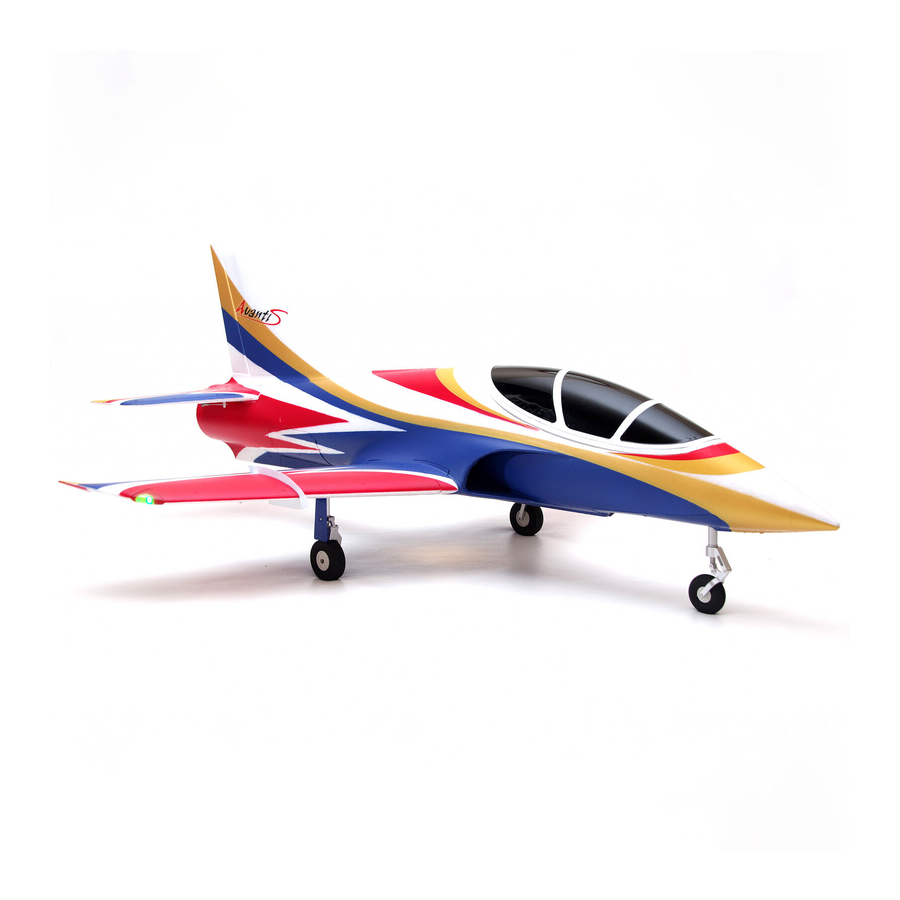
- Page 1 70MM AVANTI FMSMODEL.COM REALISTIC RIGID STABLE RETRACT & FLAPS INSTALLED STRONG DURABLE EPO SMOOTH FLYING PERFORMANCE...
- Page 3 WARNING: Read the ENTIRE instruction manual to become familiar with the features of the product before operating. Failure to operate the product correctly can result in damage to the product,personal property and cause serious injury. This is a sophisticated hobby product and NOT a toy. It must be operated with caution and common sense and failure to do so could result in injury or damage to the product or other property.
-
Page 4: Table Of Contents
······················································································································17 Introductions The fantastic 70mm EDF Avanti is coming! Avanti is a mutual-developed airplane made by FMS team from China and Sebart Team from Italy. The original design and authorization are from Sebart, with the additional FMS advanced production concept, it is finally being a promised finest work. -
Page 5: Contents Of Kit
Wingspan: 900mm (35.4in) Overall Length: 1050mm (41.3in) Flying Weight: Around 1750g Motor Size: Brushless 2860-KV1850 or 2845-KV2750 Wing Load: 101.7 g/dm² (0.23oz/in²) Wing Area: 17.2 dm² (266.6sq.in) ESC: 70A Servo: 9g metal digital Servo x 8 Contents of Kit Before assembly, please inspect the contents of the kit. The photo below details the contents of the kit and labels. -
Page 6: Model Assembly
Model Assembly Main Wing Installation 1. Slide the tube into the fuselage then install both wings over the wing tube and into the wing slot of the fuselage. (fig1) Note: The connectors on both sides should be attached precisely and firmly. 2.Secure the both wings into the fuselage using the included 4 screws. -
Page 7: Horizontal Stabilizer Installation
Model Assembly Horizontal Stabilizer Installation: 1.Connect the elevator servo connectors to the servo extensions in the fuselage. 2.Slide the horizontal tail in the rear of the fuselage. Ensure the control horn faces down as shown. (fig3) 3.Secure the horizontal tail in place using the included screw. (fig4) fig3 HKM3.0*16 fig4... -
Page 8: Vertical Stabilizer Installation
Model Assembly Vertical Stabilizer Installation: 1.Connect the rudder servo connectors to the servo extensions in the fuselage. 2.Slide the vertical tail into the slot in the fuselage. (fig5) 3.Secure the vertical tail in place using the included 2 screws. (fig6) fig5 HKM3.0*16 fig6... -
Page 9: Battery And Radio Installation
Battery and radio installation 1. Apply the loop side (soft side) of the hook and loop tape to the bottom of the battery and the hook side to the battery tray. 2. Install the fully charged battery in the battery compartment with the power supply cable toward the rear end of the plane, and secure using the hook and loop straps. -
Page 10: Important Esc And Model Information
Get your model ready to fly Important ESC and model information The ESC included with the model has a safe start. If the motor battery is connected to the ESC and the throttle stick is not in the low throttle or off position, the motor will not start until the throttle stick is moved to the low throttle or off position. -
Page 11: Check The Control Throws
Check the control throws The suggested control throw setting for FMS MODEL are as follows (dual rate setting): Tips: On first flight, fly the model in low rate. The first time you use high rates, be sure to fly at low to medium... -
Page 12: Control Horn And Servo Arm Settings
Control Horn and Servo Arm Settings The table shows the factory settings for the control horns and servo arms. Fly the aircraft at the factory settings before making changes. After flying, you may choose to adjust the linkage positions for the desired control response. See the table to the below More control throw Horns... -
Page 13: Center Of Gravity
Check the C.G. (Center of Gravity) When balancing your model, adjust the motor battery as necessary so the model is level or slightly nose down. This is the correct balance point for your model. After the first flights, the CG position can be adjusted for your personal preference. -
Page 14: Before Flying The Model
Before flying the model Find a suitable flying site Find a flying site clear of buildings, trees, power lines and other obstructions. Until you know how much area will be required and have mastered flying your plane in confined spaces, choose a site which is at least the size of two to three football fields - a flying field specifically for R/C planes is best. -
Page 15: Flying Course
Flying Course Take off While applying power, slowly steer to keep the model straight. The model should accelerate quickly. As the model gains flight speed you will want to climb at a steady and even rate. It will climb out at a nice angle of attack (AOA). -
Page 16: Trouble Shooting
Trouble shooting... -
Page 17: Spare Parts List Content
Spare parts list content FMSPX101RED Fuselage FMSPX102RED Main Wing Set FMSPX103RED Vertical Stabilizer FMSPX104RED Horizontal Stabilizer FMSPX105RED Cockpit FMSPX106 Linkage Rod FMSPX107 Screw Set FMSPX108RED Main Landing Gear Door FMSPX109 Pipe FMSPX110RED Landing Gear Set FMSPX111RED Main Landing Gear System FMSPX112RED Front Landing Gear System FMSPX113RED... -
Page 18: Esc Instruction
ESC instruction Brushless Speed Controller A quality connector Battery is essential Pack Motor Brushless Controller Receiver...
Need help?
Do you have a question about the 70MM AVANTI and is the answer not in the manual?
Questions and answers