Table of Contents
Advertisement
Quick Links
Advertisement
Table of Contents

Related Manuals for Circutor CIR-E3


Summary of Contents for Circutor CIR-E3
- Page 1 AUDITOR USER’S MANUAL (M98225801-03-09A)
-
Page 2: Table Of Contents
5.1.- ENVIRONMENTAL AND OTHER FEATURES..........11 6.-INSTALLATION AND COMMISSIONING ..............11 6.1.- CONNECTING TO AND REGISTERING IN CIR-E³WEB......12 6.1.1.- Accessing cir-e3 web ..................12 6.1.2.- Registration.......................13 6.2.- DOWNLOADING THE XCG IDENTIFICATION FILE: ........14 6.2.1.- Personal user information on the web ..............15 6.2.1.1.- User information modify................16... - Page 3 ________________________________________________________ 6.6.- START/STOP BUTTON ................30 6.7.- SAFE EXTRACTION OF THE SD MEMORY CARD........30 6.8.- INSERT SD MEMORY CARD IN A PC ............30 6.9.- TRANSFERRING DATA TO CIRE³WEB............31 6.10.- ANALYSIS AND DISPLAY OF DATA............33 6.10.1.- List of Reports....................33 6.10.2.- List of Devices....................34 6.10.3.- Parameter selection menu ................34 6.10.3.1.- Standard: ....................35...
-
Page 4: Limitation Of Liability
_____________________________________________ 1.- LIMITATION OF LIABILITY CIRCUTOR, S.A. reserves the right to modify the device or the specifications of the equipment, described in this instruction manual, without prior notice. CIRCUTOR, S.A. recommends obtaining the latest version of the unit's specifications. CIRCUTOR, S.A recommends the use of the original cables and accessories supplied with the unit. -
Page 5: Description Of The Unit
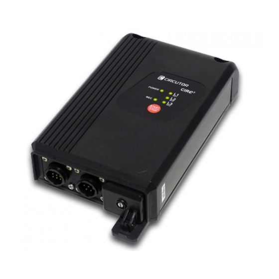
________________________________________________________ 4.- DESCRIPTION OF THE UNIT The figure shows the description and location of the analyzer's components. Connector A is used to connect the current sensors. The drawing describes the functionality of each pin. Connector B is used to connect the voltage references of the unit. Connector B is used to connect the voltage references of each phase (marked with VL1, VL2 and VL3), the neutral reference (marked with N) and two additional pins (5 and 6) used to power the unit, as shown in the figure. - Page 6 _____________________________________________ The POWER LED is on when the unit is powered. It is off when the unit is not powered. The START/STOP button has different functions, depending on the analyzer's operation. It is used to select the scale desired for the current sensors or to start or stop the recording of electrical parameters.
-
Page 7: Electrical Features
________________________________________________________ 4.1.- ELECTRICAL FEATURES Power supply circuit (connector B, brown and green wires) AC voltage 85…400 Vac DC voltage 60…315 Vdc Frequency 50…60 Hz Consumption 9 V·A Measurement circuit 10…300 Vac (p-neutral) Voltage 17…520 Vac (p-p) Current (…/2V) 5…100% Clamp E.F. Frequency 45…65 Hz 4.1.1.- MAXIMUM/MINIMUM CURRENT, DEPENDING ON THE CLAMP AND SCALE... - Page 8 _____________________________________________ The external dimensions in mm are as follows: The overhead connector layout of the voltage clamps has the following configuration. Connector pin Colour of the cable Phase BLACK (L 1) PHASE 1 (L 2) PHASE 2 YELLOW (L 3) PHASE 3 BLUE (N) NEUTRAL BROWN...
-
Page 9: Electrical Parameters
________________________________________________________ 4.3.- ELECTRICAL PARAMETERS The parameters recorded by CIR-e³ can not be selected and they are those shown on the following table. The parameters are valid for three and single-phase circuits. 4.3.1.- THREE-PHASE CIRCUIT PARAMETERS The following table shows the parameters recorded by the unit during the measurements taken in an unbalanced 4-wire three-phase system. -
Page 10: Basic Features
CIR-e³ Web application. It is located in a web site that is active 24 hours a day, 365 days a year: http://cir-e3.circutor.com. Installation: The analyzer can be installed to analyze balanced (3 wire) or unbalanced (4 wire) single and three-phase networks. -
Page 11: Environmental And Other Features
When you suspect an operational fault in the unit's protection system (for example, visible damage), disconnect the unit from any voltage or current source and contact a qualified service representative or the after sales service of CIRCUTOR, S.A. Anyone installing or using the equipment must follow the safety measures set forth and all warnings indicated in this instruction manual to guarantee a safe operation. -
Page 12: Connecting To And Registering In Cir-E³Web
6.1.- CONNECTING TO AND REGISTERING IN CIR-E³WEB The web page is a tool used to analyze and export the files recorded by the CIR-e³ analyzer. Web site: http://cir-e3.circutor.com. The access and registration procedure is described next. 6.1.1.- ACCESSING CIR-E3 WEB Open http://cir-e3.circutor.com... -
Page 13: Registration
________________________________________________________ You must register when accessing the page for the first time in order to access the Web-based application. To register, click on user?. The registration process is explained in Still do not have section 6.1.2. Registration. The fields Login and Password are used by users that have already been registered in the system: User name Login:... -
Page 14: Downloading The Xcg Identification File
Therefore, the files generated with CIR-e³ and sent by the user will be automatically sent to http://cir-e3.circutor.com and they will be located in the corresponding space, in order to allow the receiving user to access the data sent, as displayed on the Web page. -
Page 15: Personal User Information On The Web
________________________________________________________ User name User: Web space address destined to the user Address: Connection address of the data server Connection address: Data encryption key Public key: After generating the data, press “Download application file”, Press “Download application file” and the application will display the following screen, where you can select the file storage destination. -
Page 16: 1.- User Information Modify
_____________________________________________ 6.2.1.1.- User information modify The personal information menu option opens the following setup screen. The “User information modify” screen is used to modify the data configured by the user in the registration form. 6.2.1.2.- Password modify The second sub-menu in the “Personal information” menu is used to modify the Web page's access password defined by the user in the registration form. -
Page 17: 4.- Downloads
The CIR-e³ analyzer does not have configuration buttons or a setup screen and it needs a file with the configuration information required to register the data. This file has the xst extension and it is generated with the CIR-e3.exe application. This application is supplied with the unit and is stored in the SD card. - Page 18 _____________________________________________ _________________________________________________________________________________________________________ 18 of 46 CIR-e³ User’s Manual...
-
Page 19: Menu Options
________________________________________________________ 6.3.2.- MENU OPTIONS. The application has 4 different function buttons. “Configure”, “Connect” “Exit” and “Send to Web”. 6.3.2.1.- Configure Select the configure option to create a new file with the installation's features for a CIR-e³. The following window will be displayed when you click on “Configure”. Serial number: Enter the 10 digits of the serial number of the CIR-e³... - Page 20 _____________________________________________ In case you are not using voltage transformers and you are taking a direct measurement (up to 300 V p-n), the value entered must be 1. Voltage secondary: When using transformers to measure the voltage, enter the secondary voltage value of the said transformer. The information related to this feature of the transformer can be found on a features label on the transformer itself.
-
Page 21: 2.- Connect
________________________________________________________ Serial number: The serial number of the setup file is the unit's serial number. Name of the report: The name of the report is “Default”. Recording period: Established as 15 minutes Voltage primary: The transformer's primary value is 1 (direct measurement) Voltage secondary: The transformer's secondary value is 1 (direct measurement) Nominal voltage (V): The standard nominal voltage is 230 Vac Nominal Freq.: The standard frequency is 50 Hz. -
Page 22: Start-Up Sequence
_____________________________________________ The SD card should be inserted in the card slot before starting the unit, since the analyzer will be configured automatically with the default file described in section 6.3.2.1. if it does not find the setup file in the SD memory card. The card must be upside down. -
Page 23: Power And Connect The Unit
________________________________________________________ 6.5.1.- POWER AND CONNECT THE UNIT Insert connectors “A” and “B”, corresponding to the references of the current and voltage sensors of the CIR-e³ analyzer, respectively, before powering the unit. The analyzer is powered with the brown and green auxiliary power supply cables (pins 5 and 6, respectively). -
Page 24: 1.- Single-Phase Connection Diagram
_____________________________________________ To power and connect the analyzer correctly, respect the phase sequence, as shown on the table. Connector pin Colour of the cable Reference phase BLACK (L 1) PHASE 1 (L 2) PHASE 2 YELLOW (L 3) PHASE 3 BLUE (N) NEUTRAL BROWN Auxiliary power supply... -
Page 25: 2.- Three-Phase Connection Diagram (3 Wires)
________________________________________________________ 6.5.1.2.- Three-phase connection diagram (3 wires) 6.5.1.3.- Three-phase connection diagram (4 wires) _________________________________________________________________________________________________________ CIR-e³ User’s Manual 25 of 46... -
Page 26: Selecting The Scale For Flexible Clamps
_____________________________________________ After powering the analyzer, configure the scale to record data after the flexible clamps have been connected. The unit's scale selection process is explained in the next section of this manual. 6.5.2.- SELECTING THE SCALE FOR FLEXIBLE CLAMPS After inserting the voltage connectors and powering the unit, the POWER LED will turn on and search and detect the current sensors connected. -
Page 27: Verification Of Connections
________________________________________________________ If you do not select the scale manually, i.e., while the unit is in the scale selection process, the START/STOP button is not pressed and the LEDs are flashing during 30 seconds, the unit will configure the default scale automatically to start recording parameters. -
Page 28: 1.- Faulty Connection
_____________________________________________ 6.5.3.1.- Faulty connection The analyzer can indicate a faulty connection for various reasons. Phase sequence error. Current clamp is not connected correctly or is inverted. Power with a negative sign. Power factor (P.F.) is lower than 0.86 (angle > 30º). A faulty connection can be due to a problem in the connection of the voltages or currents, so that we recommend following this procedure: 1. - Page 29 ________________________________________________________ You must respect the installation position of the current sensors to guarantee the correct recording of the electrical parameters. To interpret the messages indicated by the CIRe³ unit on the L1/sc1, L2/sc2 and L3/sc3 LEDs in relation to a faulty connection of the current sensors connected to the unit, we recommend installing the clamps one by one, in order to detect individual errors.
-
Page 30: Start/Stop Button
After inserting the SD memory card in the PC or SD card reader, run the CIRe3.exe application in the root directory of the memory card. Cir-e3.exe With the CIR-e³exe application, you can send information recorded in the SD memory card with the CIR-e³ portable analyzer to the CIR-e³Web application, which can be used to display the parameters and handle the information sent. -
Page 31: Transferring Data To Cire³Web
________________________________________________________ The procedure followed to send data is explained in section 6.9 Transferring data to CIR-e³Web. 6.9.- TRANSFERRING DATA TO CIRE³WEB You must have an Internet connection to send data to the application. After inserting the SD memory card in the computer and running the CIR-e³exe application, as explained in the previous point, the following window will be displayed. - Page 32 _____________________________________________ Report description: Likewise, this space shows the name entered for the report. You can enter a description of the data report in this field if the name is not descriptive enough. This field does not have a character limitation. To send the information to the Web application, confirm the data and click on “Accept”...
-
Page 33: Analysis And Display Of Data
You must connect to the Web page in the following address to handle the information transferred to the Web page: http://cir-e3.circutor.com . Enter the page in the browser and the following application ccess screen will be displayed. To access your account and view the reports sent, fill in the access data fields with your ser registration information. -
Page 34: List Of Devices
_____________________________________________ The information displayed on this screen can be ordered in ascending or descending order in each column by clicking on the arrow under the title displayed on the top of the table: (date of the report, date of reception, report title or serial number). Select a report to display the parameters recorded in a graph. -
Page 35: 1.- Standard
________________________________________________________ 6.10.3.1.- Standard: The standard filtering process can be used to individually select each variable recorded. To do so, use the drop-down menu displayed on the following figure. If you only select one variable, it will be displayed as if you select the “Zoom” tool, explained in point 6.10.5 Zoom. -
Page 36: 2.- Harmonics
_____________________________________________ 6.10.3.2.- Harmonics: The information is displayed in a bar-chart when you select the harmonic filter mode. The default presentation screen is the voltage and current harmonics screen. The harmonics menu can be used to individually select the variables using the filtering menu on the top part of the screen. -
Page 37: Report Information
________________________________________________________ You can display each graph with more or less detail, depending on the selection. The graph is displayed on the screen as follows: This harmonics graph can use the Zoom and Table functions to display the parameters recorded in a table as the representation of the values recorded during a standard filtering operation (see section 6.10.5 Report graphs) 6.10.4.- REPORT INFORMATION This part of the visualization screen of parameters recorded and sent to the Web... -
Page 38: Report Graphs
_____________________________________________ All other information displayed in the report setup menu corresponds to the parameters configured with the CIR-e³exe application, which also corresponds to the features of the installation where the parameters were recorded. The information is related to the nominal voltage and frequency, contracted power, voltage transformer ratio and the configured scale ratio for the current sensors taking the measurements. - Page 39 ________________________________________________________ To export the images displayed in the Web-based application to a different document or format, right-click “save image as” and save the images in a folder. These can be retrieved later on when you wish to add them to a different document. Show table: The “Show table”...
- Page 40 _____________________________________________ Print: The option “print” implements a restructuring of the information displayed in the screen that allows that the user can print all the information in a single document. This option includes the header of the report and the selected graphic. _________________________________________________________________________________________________________ 40 of 46 CIR-e³...
-
Page 41: Faqs
________________________________________________________ 7.- FAQS Can I start recording when the phase LEDs start flashing? When LEDs start to flash, we recommend checking the installation to make sure that there are no connection faults. If the LEDs continue to flash after you have checked the connections, you can start the recording since this is probably due to a power factor under 0.86 (in any case, it is a real power factor value of the installation). - Page 42 _____________________________________________ What happens when the user enters an incorrect serial number when generating the setup file with the PC application? If you have created a setup file with the wrong name, i.e., the analyzer's serial number entered is incorrect, the analyzer will not use it as the unit's serial and it will configure itself with the “Default”...
-
Page 43: Regulations
Maximum input voltage 300 V Reinforced insulation 9.- TECHNICAL SERVICE Please contact the after sales service or technical service of CIRCUTOR, S.A. in case you have a question about the unit's operation or you have detected a fault. CIRCUTOR S.A. - After Sales Service. -
Page 44: Features Of The E·flex 54 Clamps
_____________________________________________ 10.- FEATURES OF THE E·FLEX 54 CLAMPS _________________________________________________________________________________________________________ 44 of 46 CIR-e³ User’s Manual... - Page 45 ________________________________________________________ _________________________________________________________________________________________________________ CIR-e³ User’s Manual 45 of 46...
-
Page 46: Ec Certificate
_____________________________________________ 11.- EC CERTIFICATE _________________________________________________________________________________________________________ 46 of 46 CIR-e³ User’s Manual...
Need help?
Do you have a question about the CIR-E3 and is the answer not in the manual?
Questions and answers